EP0497382B1 - Appareil de drainage - Google Patents
Appareil de drainage Download PDFInfo
- Publication number
- EP0497382B1 EP0497382B1 EP92103230A EP92103230A EP0497382B1 EP 0497382 B1 EP0497382 B1 EP 0497382B1 EP 92103230 A EP92103230 A EP 92103230A EP 92103230 A EP92103230 A EP 92103230A EP 0497382 B1 EP0497382 B1 EP 0497382B1
- Authority
- EP
- European Patent Office
- Prior art keywords
- chamber
- suction
- diaphragm
- patient
- pressure
- Prior art date
- Legal status (The legal status is an assumption and is not a legal conclusion. Google has not performed a legal analysis and makes no representation as to the accuracy of the status listed.)
- Expired - Lifetime
Links
- 239000007789 gas Substances 0.000 claims abstract description 30
- 239000012530 fluid Substances 0.000 claims abstract description 16
- 238000004891 communication Methods 0.000 claims description 2
- 239000003570 air Substances 0.000 description 40
- XLYOFNOQVPJJNP-UHFFFAOYSA-N water Substances O XLYOFNOQVPJJNP-UHFFFAOYSA-N 0.000 description 18
- 210000003281 pleural cavity Anatomy 0.000 description 7
- 230000001105 regulatory effect Effects 0.000 description 6
- 230000007246 mechanism Effects 0.000 description 5
- 238000000034 method Methods 0.000 description 5
- 210000000038 chest Anatomy 0.000 description 4
- 238000010586 diagram Methods 0.000 description 4
- 230000008901 benefit Effects 0.000 description 3
- 230000001276 controlling effect Effects 0.000 description 3
- 210000004072 lung Anatomy 0.000 description 3
- 238000004519 manufacturing process Methods 0.000 description 3
- 201000003144 pneumothorax Diseases 0.000 description 3
- 210000000115 thoracic cavity Anatomy 0.000 description 3
- 238000010348 incorporation Methods 0.000 description 2
- 239000007788 liquid Substances 0.000 description 2
- 238000005259 measurement Methods 0.000 description 2
- 238000005192 partition Methods 0.000 description 2
- 230000008569 process Effects 0.000 description 2
- 230000009467 reduction Effects 0.000 description 2
- 238000009877 rendering Methods 0.000 description 2
- 230000004044 response Effects 0.000 description 2
- 239000012080 ambient air Substances 0.000 description 1
- 230000000712 assembly Effects 0.000 description 1
- 238000000429 assembly Methods 0.000 description 1
- 239000008280 blood Substances 0.000 description 1
- 210000004369 blood Anatomy 0.000 description 1
- 238000009530 blood pressure measurement Methods 0.000 description 1
- 230000008859 change Effects 0.000 description 1
- 238000010276 construction Methods 0.000 description 1
- 230000008878 coupling Effects 0.000 description 1
- 238000010168 coupling process Methods 0.000 description 1
- 238000005859 coupling reaction Methods 0.000 description 1
- 238000012864 cross contamination Methods 0.000 description 1
- 238000013016 damping Methods 0.000 description 1
- 230000000694 effects Effects 0.000 description 1
- 230000008030 elimination Effects 0.000 description 1
- 238000003379 elimination reaction Methods 0.000 description 1
- 230000002708 enhancing effect Effects 0.000 description 1
- 230000008014 freezing Effects 0.000 description 1
- 238000007710 freezing Methods 0.000 description 1
- 239000000314 lubricant Substances 0.000 description 1
- 230000007257 malfunction Effects 0.000 description 1
- 239000000463 material Substances 0.000 description 1
- 238000012544 monitoring process Methods 0.000 description 1
- 230000035945 sensitivity Effects 0.000 description 1
- 230000000087 stabilizing effect Effects 0.000 description 1
Images



Classifications
-
- A—HUMAN NECESSITIES
- A61—MEDICAL OR VETERINARY SCIENCE; HYGIENE
- A61M—DEVICES FOR INTRODUCING MEDIA INTO, OR ONTO, THE BODY; DEVICES FOR TRANSDUCING BODY MEDIA OR FOR TAKING MEDIA FROM THE BODY; DEVICES FOR PRODUCING OR ENDING SLEEP OR STUPOR
- A61M1/00—Suction or pumping devices for medical purposes; Devices for carrying-off, for treatment of, or for carrying-over, body-liquids; Drainage systems
- A61M1/60—Containers for suction drainage, adapted to be used with an external suction source
- A61M1/61—Two- or three-bottle systems for underwater drainage, e.g. for chest cavity drainage
Definitions
- the invention relates to wound drainage apparatus for draining fluids from medical patients, such as from the chest cavity, by means of gas pressure differentials using low pressure gas systems.
- the 3-bottle set-up consists of a collection bottle, a water seal bottle and a suction control bottle.
- a catheter runs from the patient's pleural cavity to the collection bottle, and the suction bottle is connected by a tube to a suction source.
- the three bottles are connected in series by various tubes to apply a predetermined suction to the pleural cavity to withdraw fluid and air, and discharge the same into the collection bottle. Gases entering the collection bottle bubble through water in the water seal bottle. The water in the water seal also prevents the back flow of air into the chest cavity.
- the desired values of suction are established by the levels of water in the suction control bottle and the water seal bottle, which levels are filled according to specified values prior to the application of the system to the patient.
- a special valve referred to as the "High Negativity Valve” is included which floats closed when the patient's negativity becomes sufficient to threaten loss of the water seal.
- a "Positive Pressure Release Valve" in the large arm of the water seal chamber works to prevent a tension pneumothorax when pressure in the large arm of the water seal exceeds a prescribed value because of suction malfunction, accidental clamping or occlusion of the suction tube.
- the Pleur-evac system is disposable and helps in the battle to control cross-contamination.
- Underwater seal drainage systems as described above require the filling of manometer tubes to levels specified by the physician prior to being connected to the patient and the hospital suction system. Although it is conceivable that such filling could be performed at a manufacturing facility prior to shipment, as a practical matter this would not suffice because frequent adjustments are needed according to the different values of patient suction as dictated by the attending physician. Moreover, the presence of fluid in the various tubes could result in damage to the system during shipment such as because of freezing temperatures or because of leakage.
- US-A-4533353 which was published after the priority date claimed by this Application, discloses a wound drainage system including a collection chamber for receiving fluids from a body through an inlet port, a suction chamber communicatable with the collection chamber and connectable to a suction source, and a suction regulator for controlling the pressure in the suction chamber. It includes a device for measuring imposed suction to assist in the setting of the suction regulator but no means for measuring the rate of patient air flow.
- a further object of the invention is the provision of a chest drainage apparatus capable of regulating and measuring suction pressure in an economical, light and effective manner.
- An additional object is to provide an apparatus for draining fluid from the body, and for measuring gas flow from the body in an economical and effective manner.
- a still further object is to provide an apparatus for draining fluid from a body portion, and for measuring patient negativity in an economical and efficient manner.
- the invention in its preferred form includes a pressure regulator including adjoining compartments having an atmospheric pressure chamber, a suction chamber, a divider separating the chambers and having an opening rendering the chambers in communication, a closing member in the suction chamber biased to a position for closing the opening with a force according to the desired suction in the suction chamber, and a damping device for dampening the resultant force on the closing member.
- the invention in its preferred form includes a fluid draining apparatus including a suction chamber and a fluid collection chamber, the suction pressure being regulated by a device such as the foregoing, and means for measuring gas flowing through the collection chamber to the suction chamber by a venturi interconnecting the foregoing chambers with a measuring device connected to the throat of the venturi.
- the invention further includes in its preferred form diaphragm assemblies wherein flexing of a diaphragm operates pressure measuring means.
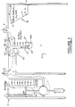
- a wound drainage apparatus 1 comprising a suction chamber 3 from which air can be evacuated by an external vacuum source such as a centrally located vacuum pump in a hospital, a suction port 4 for interconnecting chamber 3 with the external vacuum source, a suction regulator 5 for controlling the pressure in chamber 3, a collection chamber 7 for collecting fluids withdrawn from a patient, and an inlet port 9 for connecting chamber 7 to the patient.
- a venturi device 101 is provided between collection chamber 7 and suction chamber 3.
- the venturi device 101 includes a venturi tube 103 having inlet and outlet ports 105 and 107, respectively, and a throat 109.
- An L-shaped tube 111 opens into throat 109, having a constriction 113 near its vertical base and a light ball 115 disposed in the tube between constriction 113 and throat 109.
- the level of ball 115 in tube 111 is indicative of the flow rate of air through venturi tube 103, and a scale 117 is calibrated to show the value of that air flow rate. Because of the pressure differential between suction chamber 3 and collection chamber 7, air from the patient flows into port 9, through venturi tube 103, into chamber 3 and out port 4.
- Ball 115 assumes a level in tube 111 according to the air pressure differential between throat 109 and chamber 7 and the air flow rate (generally in litres per minute) can be read from scale 117.
- Device 23 includes a patient negativity diaphragm 25 extending over an opening in the outer wall of chamber 7, a push rod 26 attached to diaphragm 25 and a dial 27 mounted on a pivot 29 movable by push rod 26 for cooperating with an appropriately calibrated scale 31.
- diaphragm 25 flexes inwardly, rotating dial 29 clockwise according to the amount the diaphragm flexes to measure and indicate the extent of patient negativity.
- the pivot point of dial 27 or the connection point to push rod 26 can be equipped with a spring to urge the dial back to its zero position if a non-linkage connection is preferred.
- suction regulator 5 will be further described hereinbelow. In the meantime it suffices to mention the provision of a scale 93 calibrated in negative pressure (suction) values for cooperation with cantilever arm 55 of the suction regulator 5 to enable the setting of the force of spring 61 according to the desired suction in chamber 3.
- the modified apparatus 201 similarly to apparatus 1, comprises a suction chamber 3 from which air can be evacuated by an external vacuum source such as a centrally located vacuum pump in a hospital, a suction port 4 for interconnecting chamber 3 with the external vacuum source, a suction regulator 5 for controlling the pressure in chamber 3, a collection chamber 7 for collecting fluids withdrawn from a patient and an inlet port 9 for connecting chamber 7 to the patient.
- an external vacuum source such as a centrally located vacuum pump in a hospital
- a suction port 4 for interconnecting chamber 3 with the external vacuum source
- a suction regulator 5 for controlling the pressure in chamber 3
- a collection chamber 7 for collecting fluids withdrawn from a patient
- an inlet port 9 for connecting chamber 7 to the patient.
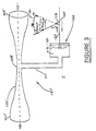
- a venturi device 101' is provided between collection chamber 7 and suction chamber 3, and is further described with reference to Figure 3.
- the vertical tube and ball arrangement is replaced with a diaphragm assembly.
- the venturi device 101' includes a venturi tube 103' having an inlet 105' and outlet 107', and a throat 109'.
- An L-shaped tube 111' communicates with throat 109' and is connected to a chamber 119.
- Patient air flow is measured by a patient air flow gauge 120.
- Gauge 120 includes a diaphragm 121 mounted in an opening in one of the walls defining chamber 119, diaphragm 121 flexing to the dotted line position according to the extent of a pressure differential between the low pressure in chamber 119 and the higher pressure in chamber 7.
- a rod 123 is attached to diaphragm 121 and is movable therewith as shown by the arrow.
- a dial 125 is attached to the end of rod 123 by means of a swivel joint 127, and is rotatable about a pivot 129 in response to movement of diaphragm 121.
- a scale 131 is disposed adjacent the free end of dial 125 and is calibrated to indicate the pressure air flow rate in litres per minute according to the position of dial 125.
- FIG. 1 The importance of detecting and measuring patient negativity (sub-atmospheric pressure in the patient) has been mentioned earlier, and the device 23 was provided for this purpose in the wound drainage apparatus 1. ( Figure 1).
- this device is replaced by a patient negativity measuring mechanism 151, which is additionally able to store the maximum recorded value of patient negativity.
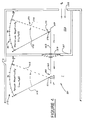
- the mechanism 151 is now described with reference to Figure 4 of the drawings.
- This mechanism includes walls defining the collection chamber 7 which communicates through port 9 with the source of the pressure being measured in the patient, an atmospheric pressure chamber 153 which communicates with the ambient air through a port 155, and a wall 157 between chambers 7 and 153 and having an opening which is sealed by a diaphragm 159.
- a rod 161 is attached to and has components 162 and 163 extending in opposite directions from diaphragm 159.
- Diaphragm 159 is flexible and moves between the unflexed position shown in solid lines and the flexed position shown in dotted lines.
- Rod portion 162 is attached to a dial 165 by means of a swivel joint 167, and rod portion 163 terminates in an upstanding flange 169.
- Dial 165 rotates clockwise about a pivot 171 in response to the flexing of diaphragm 159, and a scale 173 at the free end of dial 165 indicates the instantaneous patient negativity in appropriate units such as -cm. of water.
- a dial 175 is pivotally mounted on a pivot mechanism 177 which retains the dial in its position of maximum (clockwise) rotation.
- Mechanism 177 can for example be a ratchet device.
- Flange 169 engages the lower end of dial 175 and rotates the dial in the clockwise direction when diaphragm 159 flexes according to the amount by which the atmospheric pressure in chamber 153 exceeds the patient pressure in chamber 7''.
- a knob 179 is provided for releasing dial 177 to allow its resetting to 0.
- a scale 181 preferably calibrated in the manner of scale 173 cooperates with dial 175 to indicate the maximum patient negativity during any period of time prior to the release of dial 175 by knob 179.
- the wound drainage apparatus 201 includes, as previously noted, a suction regulator 5. Unlike the suction regulator 5 of apparatus 1, this is not provided with a calibrated scale 93 for setting the desired suction in chamber 3. It is instead provided with a suction measuring device 6. The regulation and measurement of the suction in chamber 3 are important functions of a wound drainage apparatus according to the invention.
- the operation of the suction regulator 5 ( Figures 1 and 2) and of the suction measuring device 6 are now described with reference to Figures 5 to 7 of the drawings.
- Suction regulator 5 is shown as an independent unit which would be modified for a particular application such as incorporation in the apparatus of Figures 1 and 2.
- Suction regulator 5 includes a wall 41; a horizontal partition 43 dividing regulator 5 into an upper chamber 45 and a lower chamber 47; an opening 49 in partition 43 in which is seated a collar 51, the collar being a section of a sphere and having a diameter which increases from top to bottom; a light ball 53 whose diameter is slightly more than the diameter of the sphere of which collar 51 is a section so that the ball can fit and be seated in the collar but not pass upwardly through it; a cantilever support arm 55 having a threaded bore through which extends a threaded bolt 57 with an adjustment knob 58 (which could have detents to avoid accidental changes) and disposed on a support shelf 59; a vertical guide rod 60 mounted between shelf 59 and the top wall of the unit for extending through a smooth bore in arm 55 to guide the vertical movement of arm 55; a spring 61 attached at one end
- Collar 51 preferably includes a set of notches 72 for enhancing the stabilizing effect of collar 51 on ball 53 as air flows between the collar and the ball.
- a piston chamber 74 is defined between the head of piston 67 and the closed bore of cylinder 69. Atmospheric air flow at pressure P A enters chamber 45 through an entrance port 75.
- Lower chamber 47 includes an entrance port 77 from suction chamber 3, and is connected to the hospital suction source 79 at pressure P S . Port 79 could be located in some other wall defining suction chamber 3. The path of flow is shown by the dotted arrows "a".
- the gauge pressure in suction chamber 3 is measured by negative pressure gauge 6 which is shown in detail in Figure 6.
- Gauge 6 includes a diaphragm 81 which covers an opening 83 in wall 41 between the upper chamber (which is at atmospheric pressure) of suction regulator 5 and gauge 6 (which is located in suction chamber 3), and a push rod 85 attached at one end to diaphragm 81 and at its other end to a dial 87.
- Push rod 85 should be light in weight to avoid drooping of the diaphragm.
- Dial 87 is mounted on a pivot 89 and has a free end which is movable across a negative pressure scale 91 shown calibrated in cm. of water.
- Diaphragm 81 flexes as shown in dotted lines according to the pressure differential between the pressure in chamber 3 and atmospheric pressure P A in chamber 45 (i.e. gauge pressure), and such flexure is reflected in the linear movement of push rod 85.
- Push rod 85 in turn pivots dial 87 about pivot 89 to reflect the negative pressure on scale 91.
- the short end of the dial lever arm 87 which is shown below pivot 89 is doubled back to extend in the same direction from pivot 89 as the long part of dial 87, the direction of movement of the dial and its corresponding scale can be reversed.
- the direct coupling of the push rod to the dial for effecting dial rotation could be replaced with magnetic drag between the end of the dial and the diaphragm push rod.
- the push rod and dial could be connected through a gear train with the gear ratio set to any value to accommodate different deflection or diaphragm sensitivities expected under different parameters.
- suction regulator 5 will now be explained.
- the attendant will have selected some desired negative pressure in chamber 3.
- Knob 58 is turned to raise or lower cantilever arm 55 to achieve a desired elongation of spring 61 according to the negative pressure sought.
- the pressure in upper chamber 45 will exceed the pressure in chamber 47, and the resultant force F A from atmospheric pressure P A applied over the exposed surface area A A of ball 53 in chamber 45 exceeds the resultant force F S from the negative or suction pressure P S applied over the area A S of ball 53 in chamber 47.
- Suction regulator 5 as described thus far would provide for the rapid modulation of ball 53 as the pressure differential across it varies.
- dashpot 65 is provided.
- resultant force F R becomes downward, ball 53 does not immediately pop open. Rather, the downward movement of ball 53 urges piston 67 downwardly to compress the air in piston chamber 74.
- the downward movement of piston 67 is slowed down, since air in chamber 74 compresses slowly and air can only leak out between piston 67 and the inner wall of cylinder 69 slowly.
- the resultant force F R is upward, the movement of ball 53 from its open to its closed position is also slowed down.
- the air leakage about cylinder 69 reduces the effect of friction between the cylinder wall and piston 67.
- a modified suction regulator 5' shown in Figure 7 is provided.
- This arrangement is very advantageous, because it avoids the drag which could be imposed on piston 67 without a sufficient movement of air around the piston which acts as a lubricant for the piston.
- like parts in the device of Figure 5 are given like numerals, and reference is made to the previous discussion for a description of them.
- the main difference between suction regulators 5 and 5' lies in the location of the respective dashpots.
- a dashpot 65' is located in atmospheric pressure chamber 45, and includes a piston 67', a cylinder 69' having a piston chamber 74', a support block 71' and a pivot 73' on which cylinder 69' is mounted.
- Dashpot 65' functions in the manner of dashpot 69, but the increased air flow about piston 67' can avoid the drag referred to above.
- suction regulators 5 and 5' can be incorporated in apparatus such as that in Figures 1 and 2, but they also could be incorporated in other chest drainage systems, and in other systems where gas suction must be regulated.
- the suction regulator can also be used for regulating pressure above ambient pressure, such as by admitting atmospheric air to lower chamber 47 and connecting the upper chamber to a source of higher than atmospheric pressure gas.
- FIG. 2 Certain further features of apparatus 201 ( Figure 2) are now discussed. If collection chamber 7 should be at a pressure even more negative than that of suction chamber 3 (for example, as mentioned above, when a hole in the patient's lung closes during the drainage process), it is desirable that chambers 3 and 7 should be isolated from one another, so that air does not flow from chamber 3 to chamber 7. This is accomplished by including a one way valve 203 in the venturi tube 103'.
- Chest drainage apparatus 201 includes a negativity release valve 205. This valve vents atmospheric air into collection chamber 7'' when the patient negativity exceeds the closing bias on valve 205. Valve 205 can be adjusted by means of spring tension in the manner of regulator 5, a weighted ball if a fixed value is acceptable, or a button actuated release. When the patient negativity is less than (i.e. more negative) the suction in suction chamber 3, air cannot flow from the suction chamber into tube 103 because one way valve 203 closes tube 103'.
- a positive pressure vent 207 is provided to open suction chamber 3 to the atmosphere to avoid a build-up of positive pressure air (i.e. above atmospheric pressure air) in chamber 3 should there be a failure of the suction source.
- port 4 is connected to the suction source, and the user rotates knob 58 to preset cantilever arm 55 to adjust the length of spring 61 according to the suction setting desired.
- Appropriate tubing from the patient's pleural cavity is connected to inlet 9.
- gas pressure in the pleural cavity is greater than the pressure in suction chamber 3
- gas flows into inlet 9, through tube 103 from which it exists via a one way valve 203, and out suction port 4.
- the negative or suction pressure in suction chamber 3 results in the deflection of diaphragm 81, and the value of the suction pressure is indicated by the position of dial 87 on scale 91 of gauge 6.
- the patient air flow is reflected in the amount of deflection of diaphragm 121 of patient air flow gauge 120, and this measurement is indicated by the position of dial 125 on scale 131. If the pressure in the patient's pleural cavity is subatmospheric, diaphragm 159 flexes to the left as viewed in Figure 7, and this results in the clockwise rotation of dial 165. The value of patient negativity is reflected in the position of dial 165 on scale 173. The maximum negativity is shown by the position of dial 175 on scale 181.
- the drainage apparatus provided by the present invention offer numerous advantages over the prior art.
- the apparatus in its various forms is dry, and thus avoids the various shortcomings of the systems relying on water for regulating and measuring the various pressure values.
- the apparatus and its components are of very simple construction, contributing to the ease of manufacture, use and general economy thereof.
- the apparatus and its components are compact and light, rendering it easy to store and use. Yet, despite its simplicity, it is highly effective in use.
Landscapes
- Health & Medical Sciences (AREA)
- Heart & Thoracic Surgery (AREA)
- Life Sciences & Earth Sciences (AREA)
- Public Health (AREA)
- Engineering & Computer Science (AREA)
- Anesthesiology (AREA)
- Biomedical Technology (AREA)
- Hematology (AREA)
- Pulmonology (AREA)
- Animal Behavior & Ethology (AREA)
- General Health & Medical Sciences (AREA)
- Vascular Medicine (AREA)
- Veterinary Medicine (AREA)
- External Artificial Organs (AREA)
- Sink And Installation For Waste Water (AREA)
- Electrical Discharge Machining, Electrochemical Machining, And Combined Machining (AREA)
- Centrifugal Separators (AREA)
- Iron Core Of Rotating Electric Machines (AREA)
- Cyclones (AREA)
Claims (7)
- Dispositif pour le drainage de fluides d'une portion de l'organisme d'un patient, le dispositif comprenant :une chambre de collecte (7) destinée à recevoir les fluides de l'organisme via un orifice d'entrée (9) ;une chambre d'aspiration (3) apte à communiquer avec la chambre de collecte (7) et raccordable à une source d'aspiration (PS) ; etun régulateur d'aspiration (5) pour contrôler la pression dans la chambre d'aspiration (3),
caractérisé par des moyens de Venturi (101, 101') pour faire entrer les gaz provenant de la chambre de collecte (7) dans la chambre d'aspiration (3) selon un débit fonction de la différence de pression entre la chambre de collecte (7) et la chambre d'aspiration (3), et par des moyens de mesure du débit de gaz communiquant avec la gorge (109, 109') des moyens de Venturi (101, 101'). - Dispositif selon la Revendication 1 dans lequel les moyens de mesure du débit de gaz comprennent un tube de mesure (111) communiquant avec une gorge (109) des moyens de Venturi (101), un élément animé de mouvements verticaux (115) situé dans le tube de mesure (111) et destiné à prendre une position fonction du débit de gaz dans les moyens de Venturi (101), et une graduation (117) étalonnée pour coopérer avec l'élément à mouvements verticaux (115) pour indiquer le débit de gaz dans les moyens de Venturi (101).
- Dispositif selon la Revendication 1 dans lequel les moyens de mesure du débit de gaz comprennent une chambre de mesure (119) communiquant avec une gorge (109') des moyens de Venturi (101'), un diaphragme (121) à déplacement d'air dans une paroi de la chambre de mesure (119), le diaphragme (121) à déplacement d'air fléchissant proportionnellement au débit d'air dans les moyens de Venturi (101'), des moyens de cadran (125) de l'écoulement de gaz mobiles avec le diaphragme (121) à déplacement d'air, et une graduation (131) de l'écoulement de gaz étalonnée pour coopérer avec les moyens de cadran (125) de l'écoulement de gaz pour indiquer le débit de gaz dans les moyens de Venturi (101').
- Dispositif selon l'une quelconque des Revendications précédentes, comprenant additionnellement des moyens de séparation (157) pour séparer la chambre de collecte (7) de l'atmosphère ambiante, des moyens de diaphragme (25, 159) disposés dans les moyens de séparation (157) et fléchissant proportionnellement à la négativité du patient, et des moyens (23, 151) de mesure de la négativité du patient réunis de manière opérationnelle aux moyens de diaphragme (25, 159).
- Dispositif selon la Revendication 4, dans lequel les moyens (23, 151) de mesure de la négativité du patient comprennent des moyens de cadran (27, 165) de la négativité du patient, mobiles avec les moyens de diaphragme (25, 159) et une graduation (31, 173) de la négativité du patient étalonnée pour coopérer avec les moyens de cadran (27, 165) de la négativité du patient pour indiquer la valeur de la négativité du patient.
- Dispositif selon la Revendication 4 ou 5 dans lequel les moyens (151) de mesure de la né-gativité du patient comprennent additionnellement des moyens indicateurs pour indiquer la négativité maximale du patient enregistrée pendant une période de temps, les moyens indicateurs comprenant des moyens de cadran (175) de la négativité maximale du patient mobiles par flexion des moyens de diaphragme (159) avec un développement supérieur à celui précédemment rencontré sur ladite période de temps, et une graduation maximale (181) de la négativité du patient étalonnée pour coopérer avec les moyens de cadran (175) de la négativité maximale du patient pour indiquer la négativité maximale du patient.
- Dispositif selon l'une quelconque des Revendications précédentes, caractérisé en ce que le régulateur d'aspiration (5) comprend :un premier compartiment (45) communiquant avec l'atmosphère ;un second compartiment (47) communiquant avec la chambre d'aspiration (3) ;des moyens de séparation séparant le premier compartiment (45) du second compartiment (47), les moyens de séparation comportant une ouverture (49) pour mettre le second compartiment (47) en communication avec le premier compartiment (45) ;des moyens de fermeture (53) mobiles entre une position d'ouverture pour ouvrir l'ouverture (49) et une position de fermeture pour fermer l'ouverture (49) ; etdes moyens de charge préliminaire (55-63) pour forcer les moyens de fermeture (53) vers la position fermée avec une force qui établit un équilibre des forces dans les moyens de fermeture (53) lorsque la force résultant de l'application d'une pression désirée sur les moyens de fermeture (53) se produit.
Priority Applications (1)
| Application Number | Priority Date | Filing Date | Title |
|---|---|---|---|
| EP92103230A EP0497382B1 (fr) | 1984-08-20 | 1985-08-20 | Appareil de drainage |
Applications Claiming Priority (4)
| Application Number | Priority Date | Filing Date | Title |
|---|---|---|---|
| US642564 | 1984-08-20 | ||
| US06/642,564 US4715855A (en) | 1984-08-20 | 1984-08-20 | Dry bottle drainage system |
| EP92103230A EP0497382B1 (fr) | 1984-08-20 | 1985-08-20 | Appareil de drainage |
| EP19850904327 EP0189478A4 (fr) | 1984-08-20 | 1985-08-20 | Systeme de drainage a bouteille seche. |
Related Parent Applications (2)
| Application Number | Title | Priority Date | Filing Date |
|---|---|---|---|
| EP19850904327 Division EP0189478A4 (fr) | 1984-08-20 | 1985-08-20 | Systeme de drainage a bouteille seche. |
| EP85904327.5 Division | 1986-03-05 |
Publications (3)
| Publication Number | Publication Date |
|---|---|
| EP0497382A2 EP0497382A2 (fr) | 1992-08-05 |
| EP0497382A3 EP0497382A3 (en) | 1992-10-28 |
| EP0497382B1 true EP0497382B1 (fr) | 1997-09-24 |
Family
ID=24577120
Family Applications (2)
| Application Number | Title | Priority Date | Filing Date |
|---|---|---|---|
| EP19850904327 Withdrawn EP0189478A4 (fr) | 1984-08-20 | 1985-08-20 | Systeme de drainage a bouteille seche. |
| EP92103230A Expired - Lifetime EP0497382B1 (fr) | 1984-08-20 | 1985-08-20 | Appareil de drainage |
Family Applications Before (1)
| Application Number | Title | Priority Date | Filing Date |
|---|---|---|---|
| EP19850904327 Withdrawn EP0189478A4 (fr) | 1984-08-20 | 1985-08-20 | Systeme de drainage a bouteille seche. |
Country Status (7)
| Country | Link |
|---|---|
| US (1) | US4715855A (fr) |
| EP (2) | EP0189478A4 (fr) |
| JP (2) | JPH0685799B2 (fr) |
| AT (1) | ATE158508T1 (fr) |
| CA (1) | CA1255988A (fr) |
| DE (1) | DE3588165T2 (fr) |
| WO (1) | WO1986001091A1 (fr) |
Families Citing this family (24)
| Publication number | Priority date | Publication date | Assignee | Title |
|---|---|---|---|---|
| US5026358A (en) * | 1986-10-07 | 1991-06-25 | Pfizer Products Hospital Group Inc. | Drainage device |
| US5300050A (en) * | 1986-10-07 | 1994-04-05 | Deknatel Technology Corporation | Drainage device |
| IN169588B (fr) * | 1986-10-07 | 1991-11-16 | Pfizer Hospital Prod | |
| US4784642A (en) * | 1986-10-07 | 1988-11-15 | Pfizer Hospital Products Group, Inc. | Meterless drainage device with suction control |
| US4756501A (en) * | 1986-10-07 | 1988-07-12 | Pfizer Hospital Products Group, Inc. | Hanger for drainage device |
| US5807359A (en) | 1993-06-08 | 1998-09-15 | Bemis Manufacturing Company | Medical suction system |
| US6358232B1 (en) | 1994-12-29 | 2002-03-19 | Bemis Manufacturing Company | Method and apparatus for removing and disposing of body fluids |
| US5688255A (en) * | 1994-12-29 | 1997-11-18 | Bemis Manufacturing Company | Method and apparatus for removing and disposing of body fluids |
| US5620428A (en) * | 1994-12-29 | 1997-04-15 | Bemis Manufacturing Company | Suction canister apparatus and method |
| US6244311B1 (en) | 1994-12-29 | 2001-06-12 | Bemis Manufacturing Company | Method and apparatus for removing and disposing of body fluids |
| US5683371A (en) * | 1994-12-29 | 1997-11-04 | Bemis Manufacturing Company | Suction canister apparatus and method |
| US5989234A (en) * | 1997-01-14 | 1999-11-23 | Deknatel Technology Corporation | Device and system for draining a body cavity and methods related thereto |
| US6447491B1 (en) | 1999-06-18 | 2002-09-10 | Genzyme Corporation | Rolling seal suction pressure regulator, apparatus and system for draining a body cavity and methods related thereto |
| US7674248B2 (en) | 2000-03-28 | 2010-03-09 | Bemis Manufacturing Company | Medical suction apparatus and methods for draining same |
| WO2001072350A1 (fr) | 2000-03-28 | 2001-10-04 | Bemis Manufacturing Company | Instrument d'aspiration medical et procedes de vidange de l'instrument |
| US7585292B2 (en) | 2000-03-28 | 2009-09-08 | Bemis Manufacturing Company | Medical suction apparatus and draining of same |
| WO2002055134A2 (fr) | 2001-01-12 | 2002-07-18 | Bemis Mfg Co | Procede et appareil destines a l'elimination de liquides organiques contenus dans un recipient |
| CA2446250C (fr) * | 2001-05-02 | 2009-07-14 | Axiom Medical Inc. | Necessaire de drain percutane pour fluides |
| US6955664B2 (en) * | 2001-07-17 | 2005-10-18 | D'antonio Consultants International, Inc. | Suction regulator and fluid drainage system |
| US20030069551A1 (en) * | 2001-10-05 | 2003-04-10 | Axiom Medical, Inc. | Multipurpose drain |
| US7686801B2 (en) * | 2003-02-03 | 2010-03-30 | Atrium Medical Corporation | Method and apparatus for indicating pressure in chest drainage devices |
| US8882678B2 (en) | 2009-03-13 | 2014-11-11 | Atrium Medical Corporation | Pleural drainage system and method of use |
| EP2704759A4 (fr) * | 2011-05-05 | 2015-06-03 | Eksigent Technologies Llc | Gel de couplage pour systèmes de distribution de fluide électrocinétique |
| CH709183A1 (de) * | 2014-01-30 | 2015-07-31 | Medela Holding Ag | Thoraxdrainagevorrichtung. |
Family Cites Families (25)
| Publication number | Priority date | Publication date | Assignee | Title |
|---|---|---|---|---|
| US869323A (en) * | 1906-11-07 | 1907-10-29 | Richard Peter Nolan | Automatic warning-signal for air-brake systems. |
| US1074306A (en) * | 1911-07-11 | 1913-09-30 | Franz Emil Wolf | Differential manometer. |
| US1678625A (en) * | 1924-06-18 | 1928-07-24 | Wallace & Tiernan Inc | Apparatus for the therapeutic application of chlorine |
| US2286841A (en) * | 1939-07-20 | 1942-06-16 | Linde Air Prod Co | Valve |
| US2280992A (en) * | 1940-01-08 | 1942-04-28 | Russell M Wright | Apparatus for treating nasal organs |
| US2764894A (en) * | 1953-01-26 | 1956-10-02 | Faxen Per Torsten | Apparatus for translating linear motion into rotary motion |
| US3363626A (en) | 1966-03-17 | 1968-01-16 | J A Deknatel Inc | Underwater drainage apparatus |
| US3363627A (en) | 1966-10-20 | 1968-01-16 | Deknatel Inc | Underwater drainage apparatus |
| US3559647A (en) | 1968-06-05 | 1971-02-02 | Deknatel Inc | Controllable underwater drainage apparatus |
| US3545440A (en) * | 1968-07-09 | 1970-12-08 | Deknatel Inc | Single chamber underwater drainage apparatus |
| JPS538799B1 (fr) * | 1969-12-25 | 1978-03-31 | ||
| US3683913A (en) | 1970-10-05 | 1972-08-15 | Deknatel Inc | Underwater drainage apparatus with air flow meters |
| US3763884A (en) * | 1972-02-14 | 1973-10-09 | R Grassi | Constant volume flow device |
| US3853128A (en) | 1972-07-10 | 1974-12-10 | Deknated Inc | Valved underwater drainage apparatus |
| US3782497A (en) | 1972-10-18 | 1974-01-01 | Deknatel Inc | Sound muffler for drainage device |
| US3863671A (en) * | 1973-03-12 | 1975-02-04 | Zero Manufacturing Co | Vacuum regulator control |
| FR2256056A1 (en) * | 1974-01-02 | 1975-07-25 | Eaton Corp | Power supply system for inflatable gas bag - has chamber for compressed gas valve system and combustible material heater |
| SE381986B (sv) * | 1974-01-14 | 1976-01-12 | Meteve Ab | Blodtomningsmanschett for blodtomning av extremitetet fore ett operativt ingrepp |
| US4258824A (en) | 1979-01-22 | 1981-03-31 | Bioresearch Inc. | Sound muffling baffle for drainage device |
| CA1178866A (fr) * | 1980-06-06 | 1984-12-04 | Donald P. Elliott | Appareil de drainage thoracique |
| JPS58175562A (ja) * | 1982-04-08 | 1983-10-14 | 株式会社ゼニ− | 乾式排液抽出装置 |
| US4468226A (en) * | 1982-06-08 | 1984-08-28 | Bioresearch Inc. | Surgical drainage apparatus with incremental suction control and indication |
| EP0615759B1 (fr) * | 1983-03-28 | 1996-06-12 | Deknatel Technology Corporation | Dispositif de drainage utilisable avec un écoulement par succion ou gravité |
| US4519796A (en) * | 1983-06-17 | 1985-05-28 | Russo Ronald D | Thoracic drainage device |
| US4605400A (en) * | 1984-05-04 | 1986-08-12 | Bioresearch Inc. | Surgical drainage apparatus |
-
1984
- 1984-08-20 US US06/642,564 patent/US4715855A/en not_active Expired - Lifetime
-
1985
- 1985-08-20 JP JP60503868A patent/JPH0685799B2/ja not_active Expired - Lifetime
- 1985-08-20 CA CA000489019A patent/CA1255988A/fr not_active Expired
- 1985-08-20 WO PCT/US1985/001560 patent/WO1986001091A1/fr not_active Ceased
- 1985-08-20 DE DE3588165T patent/DE3588165T2/de not_active Expired - Lifetime
- 1985-08-20 EP EP19850904327 patent/EP0189478A4/fr not_active Withdrawn
- 1985-08-20 AT AT92103230T patent/ATE158508T1/de not_active IP Right Cessation
- 1985-08-20 EP EP92103230A patent/EP0497382B1/fr not_active Expired - Lifetime
-
1993
- 1993-11-17 JP JP5323047A patent/JPH07108314B2/ja not_active Expired - Lifetime
Also Published As
| Publication number | Publication date |
|---|---|
| US4715855A (en) | 1987-12-29 |
| JPH0685799B2 (ja) | 1994-11-02 |
| DE3588165D1 (de) | 1997-10-30 |
| EP0497382A2 (fr) | 1992-08-05 |
| EP0189478A4 (fr) | 1988-06-20 |
| EP0497382A3 (en) | 1992-10-28 |
| ATE158508T1 (de) | 1997-10-15 |
| CA1255988A (fr) | 1989-06-20 |
| JPH07108314B2 (ja) | 1995-11-22 |
| EP0189478A1 (fr) | 1986-08-06 |
| JPH06285154A (ja) | 1994-10-11 |
| JPS61503012A (ja) | 1986-12-25 |
| WO1986001091A1 (fr) | 1986-02-27 |
| DE3588165T2 (de) | 1998-04-16 |
Similar Documents
| Publication | Publication Date | Title |
|---|---|---|
| US4698060A (en) | Pressure regulation system | |
| EP0497382A2 (fr) | Système de drainage | |
| US4889531A (en) | Dry bottle drainage system | |
| US4902284A (en) | Dry bottle drainage system | |
| EP0065386B1 (fr) | Appareil chirurgical de drainage avec régulation et indication de la succion | |
| US5300050A (en) | Drainage device | |
| EP0200005B1 (fr) | Système électronique de drainage | |
| US5026358A (en) | Drainage device | |
| US6955664B2 (en) | Suction regulator and fluid drainage system | |
| US4747844A (en) | Chest drainage apparatus | |
| US4738671A (en) | Chest drainage apparatus with check valve | |
| JPH01139072A (ja) | 外科用胸腔ドレン装置 | |
| US4784642A (en) | Meterless drainage device with suction control | |
| EP0263664B1 (fr) | Dispositif de drainage | |
| US5019060A (en) | Drainage blood collection apparatus | |
| CA1334645C (fr) | Drain | |
| IE58296B1 (en) | Electronic drainage system | |
| AU2003204071A1 (en) | Suction regulator and fluid drainage system |
Legal Events
| Date | Code | Title | Description |
|---|---|---|---|
| PUAI | Public reference made under article 153(3) epc to a published international application that has entered the european phase |
Free format text: ORIGINAL CODE: 0009012 |
|
| AC | Divisional application: reference to earlier application |
Ref document number: 189478 Country of ref document: EP |
|
| AK | Designated contracting states |
Kind code of ref document: A2 Designated state(s): AT BE CH DE FR GB IT LI LU NL SE |
|
| PUAL | Search report despatched |
Free format text: ORIGINAL CODE: 0009013 |
|
| AK | Designated contracting states |
Kind code of ref document: A3 Designated state(s): AT BE CH DE FR GB IT LI LU NL SE |
|
| 17P | Request for examination filed |
Effective date: 19930428 |
|
| 17Q | First examination report despatched |
Effective date: 19941201 |
|
| GRAG | Despatch of communication of intention to grant |
Free format text: ORIGINAL CODE: EPIDOS AGRA |
|
| GRAH | Despatch of communication of intention to grant a patent |
Free format text: ORIGINAL CODE: EPIDOS IGRA |
|
| GRAH | Despatch of communication of intention to grant a patent |
Free format text: ORIGINAL CODE: EPIDOS IGRA |
|
| GRAA | (expected) grant |
Free format text: ORIGINAL CODE: 0009210 |
|
| AC | Divisional application: reference to earlier application |
Ref document number: 189478 Country of ref document: EP |
|
| AK | Designated contracting states |
Kind code of ref document: B1 Designated state(s): AT BE CH DE FR GB IT LI LU NL SE |
|
| PG25 | Lapsed in a contracting state [announced via postgrant information from national office to epo] |
Ref country code: NL Free format text: LAPSE BECAUSE OF FAILURE TO SUBMIT A TRANSLATION OF THE DESCRIPTION OR TO PAY THE FEE WITHIN THE PRESCRIBED TIME-LIMIT Effective date: 19970924 Ref country code: LI Free format text: LAPSE BECAUSE OF FAILURE TO SUBMIT A TRANSLATION OF THE DESCRIPTION OR TO PAY THE FEE WITHIN THE PRESCRIBED TIME-LIMIT Effective date: 19970924 Ref country code: CH Free format text: LAPSE BECAUSE OF FAILURE TO SUBMIT A TRANSLATION OF THE DESCRIPTION OR TO PAY THE FEE WITHIN THE PRESCRIBED TIME-LIMIT Effective date: 19970924 Ref country code: BE Effective date: 19970924 Ref country code: AT Effective date: 19970924 |
|
| REF | Corresponds to: |
Ref document number: 158508 Country of ref document: AT Date of ref document: 19971015 Kind code of ref document: T |
|
| REG | Reference to a national code |
Ref country code: CH Ref legal event code: EP |
|
| ITF | It: translation for a ep patent filed | ||
| REF | Corresponds to: |
Ref document number: 3588165 Country of ref document: DE Date of ref document: 19971030 |
|
| PG25 | Lapsed in a contracting state [announced via postgrant information from national office to epo] |
Ref country code: SE Effective date: 19971224 |
|
| ET | Fr: translation filed | ||
| NLV1 | Nl: lapsed or annulled due to failure to fulfill the requirements of art. 29p and 29m of the patents act | ||
| REG | Reference to a national code |
Ref country code: CH Ref legal event code: PL |
|
| PLBE | No opposition filed within time limit |
Free format text: ORIGINAL CODE: 0009261 |
|
| STAA | Information on the status of an ep patent application or granted ep patent |
Free format text: STATUS: NO OPPOSITION FILED WITHIN TIME LIMIT |
|
| PG25 | Lapsed in a contracting state [announced via postgrant information from national office to epo] |
Ref country code: LU Free format text: LAPSE BECAUSE OF NON-PAYMENT OF DUE FEES Effective date: 19980820 |
|
| 26N | No opposition filed | ||
| REG | Reference to a national code |
Ref country code: GB Ref legal event code: IF02 |
|
| PGFP | Annual fee paid to national office [announced via postgrant information from national office to epo] |
Ref country code: GB Payment date: 20040811 Year of fee payment: 20 |
|
| PGFP | Annual fee paid to national office [announced via postgrant information from national office to epo] |
Ref country code: FR Payment date: 20040819 Year of fee payment: 20 |
|
| PGFP | Annual fee paid to national office [announced via postgrant information from national office to epo] |
Ref country code: DE Payment date: 20040930 Year of fee payment: 20 |
|
| PG25 | Lapsed in a contracting state [announced via postgrant information from national office to epo] |
Ref country code: GB Free format text: LAPSE BECAUSE OF EXPIRATION OF PROTECTION Effective date: 20050819 |
|
| REG | Reference to a national code |
Ref country code: GB Ref legal event code: PE20 |