EP0497555B1 - Verwendung von gemusterten reflektierenden Transferfolien als Aufzeichnungsmaterialien - Google Patents
Verwendung von gemusterten reflektierenden Transferfolien als Aufzeichnungsmaterialien Download PDFInfo
- Publication number
- EP0497555B1 EP0497555B1 EP92300716A EP92300716A EP0497555B1 EP 0497555 B1 EP0497555 B1 EP 0497555B1 EP 92300716 A EP92300716 A EP 92300716A EP 92300716 A EP92300716 A EP 92300716A EP 0497555 B1 EP0497555 B1 EP 0497555B1
- Authority
- EP
- European Patent Office
- Prior art keywords
- layer
- hologram
- information
- transferred
- resin
- Prior art date
- Legal status (The legal status is an assumption and is not a legal conclusion. Google has not performed a legal analysis and makes no representation as to the accuracy of the status listed.)
- Expired - Lifetime
Links
Images


Classifications
-
- G—PHYSICS
- G03—PHOTOGRAPHY; CINEMATOGRAPHY; ANALOGOUS TECHNIQUES USING WAVES OTHER THAN OPTICAL WAVES; ELECTROGRAPHY; HOLOGRAPHY
- G03H—HOLOGRAPHIC PROCESSES OR APPARATUS
- G03H1/00—Holographic processes or apparatus using light, infrared or ultraviolet waves for obtaining holograms or for obtaining an image from them; Details peculiar thereto
- G03H1/02—Details of features involved during the holographic process; Replication of holograms without interference recording
- G03H1/0276—Replicating a master hologram without interference recording
- G03H1/028—Replicating a master hologram without interference recording by embossing
-
- G—PHYSICS
- G03—PHOTOGRAPHY; CINEMATOGRAPHY; ANALOGOUS TECHNIQUES USING WAVES OTHER THAN OPTICAL WAVES; ELECTROGRAPHY; HOLOGRAPHY
- G03H—HOLOGRAPHIC PROCESSES OR APPARATUS
- G03H1/00—Holographic processes or apparatus using light, infrared or ultraviolet waves for obtaining holograms or for obtaining an image from them; Details peculiar thereto
- G03H1/02—Details of features involved during the holographic process; Replication of holograms without interference recording
- G03H1/0236—Form or shape of the hologram when not registered to the substrate, e.g. trimming the hologram to alphanumerical shape
-
- G—PHYSICS
- G03—PHOTOGRAPHY; CINEMATOGRAPHY; ANALOGOUS TECHNIQUES USING WAVES OTHER THAN OPTICAL WAVES; ELECTROGRAPHY; HOLOGRAPHY
- G03H—HOLOGRAPHIC PROCESSES OR APPARATUS
- G03H1/00—Holographic processes or apparatus using light, infrared or ultraviolet waves for obtaining holograms or for obtaining an image from them; Details peculiar thereto
- G03H1/02—Details of features involved during the holographic process; Replication of holograms without interference recording
- G03H1/0252—Laminate comprising a hologram layer
-
- G—PHYSICS
- G03—PHOTOGRAPHY; CINEMATOGRAPHY; ANALOGOUS TECHNIQUES USING WAVES OTHER THAN OPTICAL WAVES; ELECTROGRAPHY; HOLOGRAPHY
- G03H—HOLOGRAPHIC PROCESSES OR APPARATUS
- G03H1/00—Holographic processes or apparatus using light, infrared or ultraviolet waves for obtaining holograms or for obtaining an image from them; Details peculiar thereto
- G03H1/02—Details of features involved during the holographic process; Replication of holograms without interference recording
- G03H1/024—Hologram nature or properties
- G03H1/0244—Surface relief holograms
-
- G—PHYSICS
- G03—PHOTOGRAPHY; CINEMATOGRAPHY; ANALOGOUS TECHNIQUES USING WAVES OTHER THAN OPTICAL WAVES; ELECTROGRAPHY; HOLOGRAPHY
- G03H—HOLOGRAPHIC PROCESSES OR APPARATUS
- G03H1/00—Holographic processes or apparatus using light, infrared or ultraviolet waves for obtaining holograms or for obtaining an image from them; Details peculiar thereto
- G03H1/02—Details of features involved during the holographic process; Replication of holograms without interference recording
- G03H1/0276—Replicating a master hologram without interference recording
- G03H2001/0296—Formation of the master hologram
-
- G—PHYSICS
- G03—PHOTOGRAPHY; CINEMATOGRAPHY; ANALOGOUS TECHNIQUES USING WAVES OTHER THAN OPTICAL WAVES; ELECTROGRAPHY; HOLOGRAPHY
- G03H—HOLOGRAPHIC PROCESSES OR APPARATUS
- G03H1/00—Holographic processes or apparatus using light, infrared or ultraviolet waves for obtaining holograms or for obtaining an image from them; Details peculiar thereto
- G03H1/04—Processes or apparatus for producing holograms
- G03H1/18—Particular processing of hologram record carriers, e.g. for obtaining blazed holograms
- G03H1/182—Post-exposure processing, e.g. latensification
- G03H2001/183—Erasing the holographic information
- G03H2001/184—Partially erasing
-
- G—PHYSICS
- G03—PHOTOGRAPHY; CINEMATOGRAPHY; ANALOGOUS TECHNIQUES USING WAVES OTHER THAN OPTICAL WAVES; ELECTROGRAPHY; HOLOGRAPHY
- G03H—HOLOGRAPHIC PROCESSES OR APPARATUS
- G03H1/00—Holographic processes or apparatus using light, infrared or ultraviolet waves for obtaining holograms or for obtaining an image from them; Details peculiar thereto
- G03H1/04—Processes or apparatus for producing holograms
- G03H1/18—Particular processing of hologram record carriers, e.g. for obtaining blazed holograms
- G03H2001/187—Trimming process, i.e. macroscopically patterning the hologram
-
- G—PHYSICS
- G03—PHOTOGRAPHY; CINEMATOGRAPHY; ANALOGOUS TECHNIQUES USING WAVES OTHER THAN OPTICAL WAVES; ELECTROGRAPHY; HOLOGRAPHY
- G03H—HOLOGRAPHIC PROCESSES OR APPARATUS
- G03H2240/00—Hologram nature or properties
- G03H2240/50—Parameters or numerical values associated with holography, e.g. peel strength
- G03H2240/54—Refractive index
-
- G—PHYSICS
- G03—PHOTOGRAPHY; CINEMATOGRAPHY; ANALOGOUS TECHNIQUES USING WAVES OTHER THAN OPTICAL WAVES; ELECTROGRAPHY; HOLOGRAPHY
- G03H—HOLOGRAPHIC PROCESSES OR APPARATUS
- G03H2240/00—Hologram nature or properties
- G03H2240/50—Parameters or numerical values associated with holography, e.g. peel strength
- G03H2240/55—Thickness
-
- G—PHYSICS
- G03—PHOTOGRAPHY; CINEMATOGRAPHY; ANALOGOUS TECHNIQUES USING WAVES OTHER THAN OPTICAL WAVES; ELECTROGRAPHY; HOLOGRAPHY
- G03H—HOLOGRAPHIC PROCESSES OR APPARATUS
- G03H2250/00—Laminate comprising a hologram layer
- G03H2250/10—Laminate comprising a hologram layer arranged to be transferred onto a carrier body
Definitions
- the present invention relates to an information recording method wherein information recorded on a transfer foil is transferred to a substrate by a thermal recording head, for example, and information that is different from the information originally recorded on the transfer foil is recorded and displayed on the portion of the substrate where the original information has been transferred.
- Holograms in which information is recorded generally in the form of interference patterns of light, are used in various fields as high-density information recording media for recording and displaying two- and three-dimensional images and other information.
- relief holograms are formed in such a manner that a holographic interference fringe pattern is recorded in the form of a dimple pattern on a photoresist, for example, and the dimple pattern is transferred by plating, for example, to form a stamper, which is then stamped on a transparent thermoplast resin material with or without a reflecting layer of a metal or the like formed on the surface thereof, thereby making a large number of duplicates.
- Relief holograms wherein a reflecting layer, e.g., a metal layer or a high refractive index layer, is provided on the relief surface and an image is reconstructed by light reflected and diffracted by the reflecting layer include two different types, in one of which the incident light is reflected substantially completely by the reflecting layer, while in the other part of the incident light is reflected to reconstruct a hologram image on a background of transmitted light. In this application, these two types are included in the reflection relief holograms. In addition, another type of relief hologram in which the dimple pattern comprises phase diffraction grating patterns properly arranged is also considered to be included in the reflection relief holograms.
- a reflecting layer e.g., a metal layer or a high refractive index layer
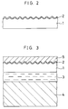
- a typical reflection relief hologram has a sectional structure shown in Fig. 2 and it comprises a hologram layer 1 of a thermoplastic resin material or the like and a reflecting layer 2 formed on a dimple interference fringe surface (i.e., relief surface) defined by the surface of the hologram layer 1.
- the reflecting layer 2 comprises either a deposited metal film, e.g., aluminum or tin, or a high refractive index transparent film, e.g., zinc sulfide. With a deposited metal film, a reflection relief hologram that reflects the incident light substantially completely by the metal is formed.
- the resulting reflection relief hologram is of the type in which part of the incident light is reflected to reconstruct a hologram image on a background of transmitted light because of Fresnel reflection based on the refractive index difference between the hologram layer 1 and the reflecting layer 2.
- Such a reflection relief hologram may be produced by either of the following two methods: one in which holographic information is recorded in the form of a dimple pattern on a photoresist, for example, and the dimple pattern is transferred by plating, for example, to form a stamper, which is then stamped on a transparent thermoplastic resin material that constitutes a hologram layer 1 to duplicate the dimple pattern, and a reflecting layer 2 is formed on the duplicated dimple pattern by deposition or the like; and the other in which a reflecting layer 2 is previously formed on a transparent resin layer that forms a hologram layer 1, and a stamper formed with the above-described dimple pattern is hot-stamped on the reflecting layer 2 to duplicate the dimple pattern (for example, see Japanese Patent Application Laid-Open (KOKAI) No. 58-65466 (1983)).
- KOKKAI Japanese Patent Application Laid-Open
- such a reflection relief hologram can be arranged in the form of a transfer foil (for example, see Japanese Patent Application Laid-Open (KOKAI) No. 01-283583 (1989)).
- Fig. 3 shows a section of the transfer foil.
- a base film 4 of PET (polyethylene terephthalate) or the like is provided on the side of the hologram layer 1 opposite to the side thereof where the reflecting layer 2 is provided, through a release layer 3 of wax or the like, and a heat-sensitive adhesive layer 5 of a vinyl chloride resin or the like is provided on the reflecting layer 2.
- the hologram layer 1 and the reflecting layer 2 in a desired profile region of a transfer foil having the above-described arrangement may be transferred to a substrate of vinyl chloride, for example, by using, for example, a thermal recording head or a hot stamper, as follows:
- the transfer foil is set in between a substrate 6 to which the hologram is to be transferred and a thermal recording head or not stamper 7 such that the heat-sensitive adhesive layer 5 faces the substrate 6, while the base film 4 faces the thermal recording head or hot stamper 7, and in this state the thermal recording head 7 is driven or the hot stamper 7 is pressed under heating.
- the reflection relief hologram has heretofore been transferred to the substrate 6, e.g., a card, as shown in Fig. 4, to display visible information, e.g. a mark, an image, etc., on a card or the like.
- the substrate 6 e.g., a card, as shown in Fig. 4
- visible information e.g. a mark, an image, etc.
- EP-A-0 328 086 discloses a resin layer having a fine dimple pattern, e.g., a relief hologram on the surface thereof; a reflecting layer formed on the dimpled surface of said resin layer; and a releasable base film stacked on the side of said resin layer which is opposite to the side thereof where said reflecting layer is provided.
- EP-A-0 420 261 which is prior art under Article 54(3) EPC, discloses an information recording method similar to the present invention, but does not specify the use of a thermal head as a heating means.
- the invention provides an information recording method comprising a step of preparing a transfer foil having a reflection relief hologram comprising at least a resin layer having a fine dimple pattern of a relief hologram or a relief diffraction grating formed on the surface thereof, and a reflecting layer formed on the dimpled surface of the resin layer, at least a part of the reflection relief hologram being formed as a transferable region; a step of transferring a predetermined portion of the transferable region to the surface of an object to which information is to be transferred; and a step of heating at least a part of the transferred portion with a thermal head, thereby destroying the reflecting layer, wherein said part of the transferred portion represents information, such as an image or character other than the information originally recorded on the reflection relief hologram, to the transferred hologram.
- the invention also provides an information recording method comprising a step of preparing a transfer foil having a reflection relief hologram comprising at least a resin layer having a fine dimple pattern of a relief hologram, a relief diffraction grating formed on the surface thereof, and a reflecting layer formed on the dimpled surface of the resin layer, at least a part of the reflection relief hologram being formed as a transferable region, a step of transferring a predetermined portion of the transferable region to the surface of an object to which information is to be transferred; and a step of heating at least a part of the transferred portion with a thermal head, thereby smoothing a dimple pattern formed by the surface of the resin layer and the reflecting layer, wherein said part of the transferred portion represents information, such as an image or character other than the information originally recorded on the reflection relief hologram, to the transferred hologram.
- a transfer foil having a reflection relief hologram comprising a resin layer and a reflecting layer at least a part of the reflection relief hologram being formed as a transferable region, transferring a predetermined portion of the transferable region to the surface of an object to which information is to be transferred, and heating at least a part of the transferred portion with a heating means, thereby destroying the reflecting layer, or smoothing a dimple pattern formed by the surface of the resin layer and the reflecting layer.
- the invention accordingly comprises the features of construction, combinations of elements, and arrangements of parts which will be exemplified in the construction hereinafter set forth.
- Fig.1(a) shows a reflection relief hologram 10 transferred to the surface of a substrate 6.
- a hologram with a desired profile which comprises a hologram layer 1 and a reflecting layer 2, is bonded to the surface of the substrate 6 by a heat-sensitive adhesive layer 5, as described above, and has image information 11 recorded thereon, as shown in the plan view of Fig.1(b).
- desired ones of the heating elements 8 are driven.
- respective portions of the hologram layer 1 and the reflecting layer 2 which correspond to the driven heating elements 8 are heated rapidly.
- the heating By the heating, the metal or other material constituting the thin reflecting layer 2 is melted and then cracks finely because of surface tension, thus losing its reflecting properties. As a result, this portion of the substrate 6 can be seen through the reflecting layer 2. Accordingly, if the substrate 1 is colored in advance, for example, and the heating elements 8 are selectively driven sequentially on the basis of information desired to record, information 12, for example, a character or an image, can be recorded and displayed in addition to the information 11 originally recorded on the hologram.
- information 12 for example, a character or an image
- the reflecting layer 2 is selectively evaporated and information is thus recorded when the heat temperature applied by the heating means is high, or depending upon the material or thickness of the reflecting layer 2. Even if the reflecting layer 2 is not destroyed, the dimpled surfaces of the hologram layer 1 and the reflecting layer 2 return to the flat surfaces because of melt softening and the hologram in a selected region is erased, so that the selected region becomes different in contrast, color, etc. from the other region, thus enabling information to be recorded and displayed in the same way.
- a material for the base film 4 biaxially oriented polyethylene terephthalate film is most preferable from the viewpoint of dimensional stability, heat resistance, toughness, etc.
- Other materials usable for the base film 4 are synthetic films such as polyvinyl chloride film, polypropylene film, polyethylene film, polycarbonate film, regenerated cellulose, Vinylon (trademark) film, acetate film, nylon film, polyvinyl alcohol film, polyamide film on a polyamide-imide film, and paper such as condenser paper.
- the thickness of the base film 4 is preferably of the order of 6 ⁇ m to 12 ⁇ m.
- the release layer 3 is provided for the purpose of improving release characteristics and foil breaking characteristics.
- various known materials can be used in accordance with the kind of the base film 4, for example, polymethacrylate resin, polyvinyl chloride resin, cellulose resin, silicone resin, wax containing hydrocarbon as a principal component, polystyrene resin, chlorinated rubber, casein, various kinds of surface-active agent or metallic oxides, etc. These materials can be used alone or in the form of a mixture of two or more so that the peel strength of the release layer 3 is 1 g/inch to 5 g/inch (peeling at 90 degrees)) in combination with the base film 4.
- the release layer 3 may be formed as a thin film on the base film 4 by a known method, for example, by coating the material in the form of ink.
- the thickness of the release layer 3 is preferably in the range of from 0.1 ⁇ m to 1.0 ⁇ m when the peel strength and foil breaking characteristics are taken into consideration.
- hologram layer 1 various kinds of resin material can be selected with the foil breaking characteristics and transfer heat resistance taken into consideration.
- resin material for the hologram layer 1 are unsaturated polyester resin, acryl urethane resin, epoxy modified acrylic resin, epoxy modified unsaturated polyester resin, acrylic ester resin, acrylamide resin, nitrocellulose resin, polystyrene resin, alkyd resin, or phenolic resin, etc. These materials may be used alone or in the form of a mixture of two or more.
- a heat- or ultraviolet- curing agent selected from among isocyanate resins, metallic soaps such as cobalt naphthenate and lead naphthenate, peroxides such as benzoyl peroxide and methyl ethyl ketone peroxide, benzophenone, acetophenone, anthraquinone, naphthoquinone, azobisisobutyronitrile and diphenyl sulfide.
- the glass transition temperature is higher than the heat temperature applied during the heat transfer process. Specifically, it is preferable that the glass transition temperature should be 100°C to 200°C.
- the hologram resin layer 1 can be formed by coating the material in the form of ink according to a known method.
- the foil breaking characteristics film breaking strength
- the thickness of the hologram resin layer 1 is preferably in the range of from 0.5 ⁇ m to 2.0 ⁇ m.
- a reflective thin film layer for forming the reflecting layer 2 is provided on the surface of the hologram resin layer 1 by deposition, sputtering, ion plating, electrolytic plating, electroless plating, etc. using a metal, a metallic compound, glass, etc.
- the reflective thin film layer 2 In the case of a reflection hologram, a metal thin film that reflects light is employed as the reflective thin film layer 2, whereas in the case of a transparent hologram, a holographic effect thin film is employed which exhibits holographic effect in combination with the resin layer 1 and which does not conceal the underlying layer.
- the reflective thin film may be properly selected according to the purpose.
- metal thin films usable for a reflection hologram are metals such as Cr, Ti, Fe, Co, Ni, Cu, Ag, Au, Ge, Al, Mg, Sb, Pb, Pd, Cd, Bi, Sn, Se, In, Ga, Rb, and oxides and nitrides of these metals. These materials may be used alone or a combination of two or more. Among the above-mentioned metals, Al, Cr, Ni, Ag and Au are particularly preferable.
- the film thickness is preferably 10 ⁇ to 10,000 ⁇ , more preferably 200 ⁇ to 2,000 ⁇ .
- the holographic effect thin film that is employed for a transparent hologram may be made of any material as long as it transmits light so that the holographic effect can be exhibited.
- Examples of such material include a transparent material which is different in refractive index from the resin layer 1, and a reflective metal thin film layer having a thickness of not larger than 200 ⁇ .
- the refractive index may be either larger or smaller than that of the resin layer 1, but the refractive index difference is preferably 0.1 or more, more preferably 0.5 or more. According to an experiment carried out by the present inventors, a refractive index difference of 1.0 or more is the most suitable.
- the thickness is not larger than 200 ⁇ , the light wave transmission factor is large, so that the required holographic effect can be exhibited and, at the same time, the underlying layer can be seen through the layer 2.
- the film thickness is set at 200 ⁇ or less, the incongruity in the appearance that has heretofore been given by silver gray of high brightness is eliminated.
- Examples of materials usable for the thin film layer 2 include those described below (1) to (6).
- Transparent continuous thin films having a larger refractive index than that of the resin layer 1 This type of thin film include those which are transparent in the visible region and those which are transparent in either the infrared or ultraviolet region.
- the former materials are shown in Table 1 below, and the latter materials in Table 2 below.
- n denotes refractive index (the same is the case with the materials (2) to (5)).
- Table 2 Materials which are transparent in either the infrared or ultraviolet region Materials n CdSe 3.5 CdTe 2.6 Ge 4.0 to 4.4 HfO 2 2.2 PbTe 5.6 Si 3.4 Te 4.9 TlCl 2.6 ZnTe 2.8 (2) Transparent ferroelectric materials having a larger refractive index than that of the resin layer 1 are shown in Table 3 below. (3) Transparent continuous thin films having a smaller refractive index than that of the resin layer 1 are shown in Table 4 below. Table 4: Materials n LiF 1.4 MgF 2 1.4 3NaF ⁇ AlF 3 1.4 AlF 3 1.4 NaF 1.3 GaF 2 1.3 (4) Reflective metal thin films having a thickness of not larger than 200 ⁇ .
- Materials of reflective metal thin film layers usable in the first invention are shown in Table 5 below, together with n and K.
- Resins which are different in refractive index from the resin layer 1 The refractive index of these resins may be either larger or smaller than that of the resin layer 1. Examples of such resins are shown in Table 6 below. Table 6: Resins n Polytetrafluoroethylene 1.35 Polychlorotrifluoroethylene 1.43 Vinyl acetate resin 1.46 Polyethylene 1.52 Polypropylene 1.49 Methyl methacrylate 1.49 Nylon 1.53 Polystyrene 1.60 Polyvinylidene chloride 1.62 Vinyl butyral resin 1.48 Vinyl formal resin 1.50 Polyvinyl chloride 1.53 Polyester resin 1.55 Phenol-formalin resin 1.60 It is possible to use ordinary synthetic resins in addition to the above, and it is particularly preferable to use a resin which is largely different in refractive index from the resin layer 1. (6) Laminates obtained by suitably combining the materials (1) to (5): The materials (1) to (5) may be combined with each other as desired, and the positional relationship between the layers of a laminate may be selected
- the thin film layer (4) has a thickness of not larger than 200 ⁇ , whereas the thickness of the thin film layers (1) to (3), (5) and (6) may be determined as desired as long as the material forming the thin film is transparent in the relevant spectral region; in general, the thickness is preferably 10 ⁇ to 10,000 ⁇ , more preferably 100 ⁇ to 5,000 ⁇ .
- the holographic effect layer 2 can be formed on the resin layer 1 by using a conventional thin film forming means, e.g., vacuum deposition, sputtering, reactive sputtering, ion plating, electrolytic plating, etc., whereas, when the thin film layer 2 is made of the material (5), a conventional coating method can be employed.
- a conventional thin film forming means e.g., vacuum deposition, sputtering, reactive sputtering, ion plating, electrolytic plating, etc.
- a conventional coating method can be employed.
- the thin film layer 2 is made of the material (6)
- the above-mentioned means and methods may be properly combined together.
- the thickness of the holographic effect layer 2 is preferably 100 ⁇ to 600 ⁇ , in general. If the thickness is less than 100 ⁇ , the reflecting effect becomes inadequate, whereas, if the thickness exceeds 600 ⁇ , the embossing characteristics lower considerably.
- a stamper for embossing such a transfer foil can be produced by a known method.
- the stamper needs high pressure resistance and satisfactorily high hardness and tensile strength because a fine dimple pattern on the surface thereof must be pressed into the mating substrate completely. For this reason, it is most suitable to obtain a stamper by electrolytic Ni plating method.
- the emboss substrate (comprising the base film 4, the release layer 3, the hologram layer 1 and the reflecting layer 2) and the stamper, which are obtained as described above, are put one on top of the other in such a manner that the reflecting layer 2 of the substrate film and the dimpled surface of the stamper are brought into contact with each other, and are then heat-pressed, thereby transferring the dimple pattern to both the reflecting layer 2 and the resin layer 1. Thereafter, a heat-sensitive adhesive layer 5 of a vinyl chloride resin or the like is provided on the reflecting layer 2 to complete a transfer foil.
- a release layer of wax with a peel strength of 5 g/inch was provided to a thickness of 0.5 ⁇ m on the surface of a base film of PET having a thickness of 12 ⁇ m, and a hologram layer of acryl urethane resin with a thickness of 1.0 ⁇ m was coated on the release layer. Further, aluminum was evaporated to a thickness of 300 ⁇ on the hologram layer to obtain a laminate for duplicate.
- a relief hologram stamper formed by nickel plating was pressed under heating against the reflecting layer side of the laminate to make a duplicate of the relief hologram. Thereafter, a heat-sensitive adhesive layer of a vinyl chloride-acetate resin was coated to a thickness of 3 ⁇ m on the duplicate side of the laminate and then dried to thereby produce a reflection relief hologram transfer foil.
- the hologram transfer foil obtained in this way was laid on a PET film (188 ⁇ m) coated at the surface thereof with a vinyl chloride-acetate resin, and heat transfer was effected at 0.6 mJ/dot by using a thin-film thermal head (8 dots/mm).
- the transfer printed section thus obtained was superior in the foil breaking characteristics, adhesion, etc., and all the dots were resolved.
- the transfer printed section with the above-described contents was heated again at 1.0 mJ/dot with the thermal head.
- the release layer, the resin layer and the reflecting layer in the reheated portion were melted and destroyed, and the reflecting layer disappeared in the reheated pattern.
- the information recording method of the invention it is possible to add information, e.g., an image or a character, other than information originally recorded on a reflection relief hologram by preparing a transfer foil having a reflection relief hologram comprising a resin layer and a reflecting layer, at least a part of the reflection relief hologram being formed as a transferable region, transferring a predetermined portion of the transferable region to the surface of an object to which information is to be transferred, and heating at least a part of the transferred portion with a heating means, thereby destroying the reflecting layer, or smoothing a dimple pattern formed by the surface of the resin layer and the reflecting layer.
- a transfer foil having a reflection relief hologram comprising a resin layer and a reflecting layer, at least a part of the reflection relief hologram being formed as a transferable region, transferring a predetermined portion of the transferable region to the surface of an object to which information is to be transferred, and heating at least a part of the transferred portion with a heating means, thereby destroying
Landscapes
- Physics & Mathematics (AREA)
- General Physics & Mathematics (AREA)
- Holo Graphy (AREA)
- Decoration By Transfer Pictures (AREA)
Claims (2)
- Informationsaufzeichnungsverfahren, umfassend einen Schritt zur Herstellung einer Transferfolie mit einem Reflexionsreliefhologramm (10) umfassend wenigstens eine Harzschicht mit einem feinen, auf deren Oberfläche gebildeten Vertiefungsmuster (1) eines Reliefhologramms oder eines Beugungsgitterreliefs, und eine auf der vertieften Oberfläche der Harzschicht gebildete Reflexionsschicht (2), wobei wenigstens ein Teil des Reflexionsreliefhologramms als übertragbarer Bereich ausgebildet ist;einen Schritt zur Übertragung eines vorbestimmten Abschnitts des übertragbaren Bereichs auf die Oberfläche eines Objekts, an das Information zu übertragen ist; undeinen Schritt zur Erwärmung wenigstens eines Teils des übertragenen Abschnitts mit einem Wärmekopf (7), wodurch die Reflexionsschicht zerstört wird, wobei der Teil des übertragenen Abschnitts zugefügte Information (12) zu dem übertragenen Hologramm darstellt, beispielsweise ein Bild oder ein Zeichen anders als die ursprünglich auf dem Reflexionsreliefhologramm aufgezeichnete Information (11).
- Informationsaufzeichnungsverfahren, umfassend einen Schritt zur Herstellung einer Transferfolie mit einem Reflexionsreliefhologramm (10) umfassend wenigstens eine Harzschicht mit einem feinen, auf deren Oberfläche gebildeten Vertiefungsmuster (1) eines Reliefhologramms oder eines Beugungsgitterreliefs, und eine auf der vertieften Oberfläche der Harzschicht gebildete Reflexionsschicht (2), wobei wenigstens ein Teil des Reflexionsreliefhologramms als übertragbarer Bereich ausgebildet ist;einen Schritt zur Übertragung eines vorbestimmten Abschnitts des übertragbaren Bereichs auf die Oberfläche eines Objekts, an das Information zu übertragen ist; undeinen Schritt zur Erwärmung wenigstens eines Teils des übertragenen Abschnitts mit einem Wärmekopf (7), wodurch ein von der Oberfläche der Harzschicht und der Reflexionsschicht gebildetes Vertiefungsmuster geglättet wird, wobei der Teil des übertragenen Abschnitts zugefügte Information (12) zu dem übertragenen Hologramm darstellt, beispielsweise ein Bild oder ein Zeichen anders als die ursprünglich auf dem Reflexionsreliefhologramm aufgezeichnete Information (11).
Priority Applications (1)
| Application Number | Priority Date | Filing Date | Title |
|---|---|---|---|
| EP95201359A EP0677400B1 (de) | 1991-01-28 | 1992-01-28 | Transferfolie mit gemusterten reliefartigen Oberfläche aufweisenden reflektierender Schicht |
Applications Claiming Priority (6)
| Application Number | Priority Date | Filing Date | Title |
|---|---|---|---|
| JP3008384A JP2877968B2 (ja) | 1991-01-28 | 1991-01-28 | 情報記録方法及び情報記録媒体 |
| JP8384/91 | 1991-01-28 | ||
| JP1218391A JPH04247486A (ja) | 1991-02-01 | 1991-02-01 | 反射型レリーフホログラムの転写箔及びそれを用いた反射型レリーフホログラムの選択的転写方法 |
| JP12183/91 | 1991-02-01 | ||
| JP43932/91 | 1991-03-11 | ||
| JP4393291A JPH04281489A (ja) | 1991-03-11 | 1991-03-11 | 反射層を有する微細凹凸パターンの転写箔及びその製造方法 |
Related Child Applications (2)
| Application Number | Title | Priority Date | Filing Date |
|---|---|---|---|
| EP95201359A Division EP0677400B1 (de) | 1991-01-28 | 1992-01-28 | Transferfolie mit gemusterten reliefartigen Oberfläche aufweisenden reflektierender Schicht |
| EP95201359.7 Division-Into | 1995-05-24 |
Publications (2)
| Publication Number | Publication Date |
|---|---|
| EP0497555A1 EP0497555A1 (de) | 1992-08-05 |
| EP0497555B1 true EP0497555B1 (de) | 1997-07-09 |
Family
ID=27277997
Family Applications (2)
| Application Number | Title | Priority Date | Filing Date |
|---|---|---|---|
| EP95201359A Revoked EP0677400B1 (de) | 1991-01-28 | 1992-01-28 | Transferfolie mit gemusterten reliefartigen Oberfläche aufweisenden reflektierender Schicht |
| EP92300716A Expired - Lifetime EP0497555B1 (de) | 1991-01-28 | 1992-01-28 | Verwendung von gemusterten reflektierenden Transferfolien als Aufzeichnungsmaterialien |
Family Applications Before (1)
| Application Number | Title | Priority Date | Filing Date |
|---|---|---|---|
| EP95201359A Revoked EP0677400B1 (de) | 1991-01-28 | 1992-01-28 | Transferfolie mit gemusterten reliefartigen Oberfläche aufweisenden reflektierender Schicht |
Country Status (3)
| Country | Link |
|---|---|
| US (1) | US5300169A (de) |
| EP (2) | EP0677400B1 (de) |
| DE (2) | DE69220686T2 (de) |
Families Citing this family (58)
| Publication number | Priority date | Publication date | Assignee | Title |
|---|---|---|---|---|
| US5626702A (en) * | 1991-05-17 | 1997-05-06 | Holotex Limited | Process for production of flexible laminate |
| GB9122247D0 (en) * | 1991-10-19 | 1991-12-04 | Applied Holographics | Optical data storage disc |
| GB9202940D0 (en) * | 1992-02-12 | 1992-03-25 | Amblehurst Ltd | Image enchancement |
| GB9203568D0 (en) * | 1992-02-20 | 1992-04-08 | Amblehurst Ltd | Transfer method and device |
| DE4211235C2 (de) * | 1992-04-03 | 2003-04-17 | Gao Ges Automation Org | Verfahren und Vorrichtung zur Herstellung metallischer Flächenelemente auf Substraten und deren Verwendung |
| DE4404128A1 (de) † | 1993-02-19 | 1994-08-25 | Gao Ges Automation Org | Sicherheitsdokument und Verfahren zu seiner Herstellung |
| US5464690A (en) * | 1994-04-04 | 1995-11-07 | Novavision, Inc. | Holographic document and method for forming |
| DE4423291A1 (de) * | 1994-07-02 | 1996-01-11 | Kurz Leonhard Fa | Prägefolie, insbesondere Heissprägefolie mit Dekorations- oder Sicherungselementen |
| ES2120704T5 (es) * | 1995-05-05 | 2002-06-16 | Ovd Kinegram Ag | Procedimiento para aplicar un elemento de seguridad sobre un substrato. |
| JPH08310170A (ja) * | 1995-05-18 | 1996-11-26 | Dainippon Printing Co Ltd | ホログラム付き印画物及びその作成方法 |
| ES2124152B1 (es) * | 1995-10-30 | 1999-11-16 | Romano Juan Jose Grao | Perfeccionamientos introducidos en un procedimiento de fabricacion de calcomanias de impresion eliminable rapidamente. |
| US6309580B1 (en) * | 1995-11-15 | 2001-10-30 | Regents Of The University Of Minnesota | Release surfaces, particularly for use in nanoimprint lithography |
| DE69700061T2 (de) * | 1996-06-10 | 1999-10-21 | Dai Nippon Printing Co., Ltd. | Thermische Übertragungsschicht für das Erzeugen von Bildern mit metallischem Glanz |
| US5746865A (en) * | 1996-07-09 | 1998-05-05 | Hampshire Holographic Manufacturing Corp. | Process for transferring holographic images |
| EP0869408B2 (de) * | 1996-09-19 | 2015-04-29 | Dai Nippon Printing Co., Ltd. | Mehrschichtiges volumenhologramm und etikett zur herstellung eines mehrschichtigen volumenhologramms |
| KR100536868B1 (ko) * | 1997-10-03 | 2006-02-28 | 다이니폰 인사츠 가부시키가이샤 | 전사시트 |
| US6340985B1 (en) * | 1997-12-10 | 2002-01-22 | Fuji Photo Film Co. Ltd. | Thermal recording apparatus |
| DE69917844T2 (de) * | 1998-03-06 | 2005-06-23 | Dai Nippon Printing Co., Ltd. | Zwischenträger eines übertragungsaufzeichnungsmaterials, verfahren zur herstellung eines druckes, sowie entsprechendes druckerzeugnis |
| AU744721B2 (en) * | 1998-09-28 | 2002-02-28 | Wea Manufacturing Inc. | Dual-layer DVD disc, and method and apparatus for making same |
| US7946226B1 (en) * | 1998-10-23 | 2011-05-24 | Harald Kaufmann | Serigraphy reflection transfer and product and method for producing the same |
| EP2309339B1 (de) | 1999-01-19 | 2016-11-30 | Dai Nippon Printing Co., Ltd. | Blatt mit Oberflächenstruktur-Hologramm oder Beugungsgitter und damit ausgestattetes fälschungsicheres Blatt |
| US7095164B1 (en) * | 1999-05-25 | 2006-08-22 | Intel Corporation | Display screen |
| US20070195392A1 (en) * | 1999-07-08 | 2007-08-23 | Jds Uniphase Corporation | Adhesive Chromagram And Method Of Forming Thereof |
| US6497778B1 (en) | 2000-04-19 | 2002-12-24 | Novavision, Inc. | Method for making holographic foil |
| US6638386B2 (en) | 2000-04-19 | 2003-10-28 | Novavision, Inc. | Method for making holographic foil |
| DE10039374A1 (de) * | 2000-08-11 | 2002-02-21 | Eml Europ Media Lab Gmbh | Holographischer Datenspeicher |
| DE10039372C2 (de) * | 2000-08-11 | 2003-05-15 | Tesa Scribos Gmbh | Holographischer Datenspeicher |
| DE10128902A1 (de) * | 2001-06-15 | 2003-10-16 | Tesa Scribos Gmbh | Holographischer Datenspeicher |
| JP2005535483A (ja) * | 2002-08-09 | 2005-11-24 | レオナード クルツ ゲーエムベーハー ウント コンパニー カーゲー | レーザー支援複製プロセス |
| DE10236597A1 (de) * | 2002-08-09 | 2004-02-19 | Leonhard Kurz Gmbh & Co. Kg | Laserunterstütztes Replizierverfahren |
| DE10236810A1 (de) * | 2002-08-10 | 2004-02-26 | Leonhard Kurz Gmbh & Co. Kg | Teilstrukturierte IMD-fähige Mehrschichtfolie |
| CA2512086C (en) | 2003-01-03 | 2012-04-10 | American Express Travel Related Services Company, Inc. | Metal-containing transaction card and method of making the same |
| US7823777B2 (en) | 2003-01-03 | 2010-11-02 | American Express Travel Related Services Company, Inc. | Metal-containing transaction card and method of making same |
| US8033457B2 (en) | 2003-01-03 | 2011-10-11 | American Express Travel Related Services Company, Inc. | Metal-containing transaction card and method of making the same |
| US7588184B2 (en) * | 2003-01-03 | 2009-09-15 | American Express Travel Related Services Company, Inc. | Metal-containing transaction card and method of making the same |
| JP4397728B2 (ja) * | 2004-04-21 | 2010-01-13 | 日東電工株式会社 | 直下型バックライト |
| JP4826142B2 (ja) * | 2005-06-03 | 2011-11-30 | 大日本印刷株式会社 | 熱転写シートの製造方法及び熱転写方法 |
| ES2600203T3 (es) * | 2005-10-27 | 2017-02-07 | Ovd Kinegram Ag | Método para transferir un cuerpo multicapa; película de transferencia |
| US20070102103A1 (en) * | 2005-11-07 | 2007-05-10 | Klaser Technology Inc. | Manufacturing method for printing circuit |
| US20070195262A1 (en) * | 2006-02-23 | 2007-08-23 | Herbert Mosse | Method for providing a polarizing layer on an optical element |
| JP2009178843A (ja) | 2006-08-22 | 2009-08-13 | Rynne Group Llc | 識別カードおよびその識別カードを使用した識別カード取引システム |
| JP5384364B2 (ja) * | 2006-12-14 | 2014-01-08 | コルゲート・パーモリブ・カンパニー | ホログラムが出現するパッケージ画像 |
| KR101482811B1 (ko) * | 2007-07-03 | 2015-01-14 | 도요세이칸 그룹 홀딩스 가부시키가이샤 | 홀로그램 패턴 형성 방법, 홀로그램 패턴이 구비된 필름 제조 방법, 적층 필름 및 용기 |
| WO2009113094A2 (en) * | 2008-01-22 | 2009-09-17 | Essel Propack Ltd. | Multilayer flexible sheet and method thereof |
| EP2258564B1 (de) * | 2009-06-03 | 2012-05-23 | Valtion Teknillinen Tutkimuskeskus | Verfahren zur Erzeugung eines optischen Beugungseffekts auf einer Zielfläche |
| DE102010001511B4 (de) | 2010-02-02 | 2012-07-12 | Harald Kaufmann | Verfahren zum Herstellen eines Textilprodukts |
| JP2013145366A (ja) * | 2011-12-14 | 2013-07-25 | Dainippon Printing Co Ltd | オンデマンドによる可変形状ホログラムの製造方法 |
| EP2716471B1 (de) | 2012-10-05 | 2016-05-11 | Reflectra USA Inc. | Verfahren zum Herstellen eines Reflexionstransfers zum Übertragen eines Motivs auf ein Substrat |
| US10099462B2 (en) * | 2013-06-28 | 2018-10-16 | Toray Plastics (America), Inc. | Releasable polyester high gloss metal transfer film |
| US9630385B2 (en) | 2012-11-08 | 2017-04-25 | Toray Plastics (America), Inc. | Releasable polyester metal transfer film |
| US9299130B2 (en) | 2013-03-15 | 2016-03-29 | Trustees Of Tufts College | Methods and apparatus for image processing and analysis |
| DE102013015689A1 (de) * | 2013-09-16 | 2015-03-19 | Giesecke & Devrient Gmbh | Streifenförmige Endlosfolie und deren Verwendung |
| EP3132316A1 (de) * | 2014-04-18 | 2017-02-22 | E. I. du Pont de Nemours and Company | Mehrschichtige folie und authentifizierungsetikett |
| JPWO2016194385A1 (ja) * | 2015-06-02 | 2018-06-07 | 凸版印刷株式会社 | 積層体およびその製造方法 |
| US10809448B1 (en) * | 2019-04-18 | 2020-10-20 | Facebook Technologies, Llc | Reducing demolding stress at edges of gratings in nanoimprint lithography |
| CN110767074A (zh) * | 2019-11-11 | 2020-02-07 | 深圳市甲古文创意设计有限公司 | 一种全息光刻滴胶牌 |
| CN112759929B (zh) * | 2021-01-20 | 2022-08-23 | 金旸(厦门)新材料科技有限公司 | 一种高刚性玻纤增强阻燃耐磨尼龙材料 |
| DE102024127058A1 (de) * | 2024-09-19 | 2025-06-18 | Leonhard Kurz Stiftung & Co. Kg | Dekorfolie, Verfahren zur Herstellung einer Dekorfolie und Verfahren zur Dekoration eines Zielsubstrats |
Citations (1)
| Publication number | Priority date | Publication date | Assignee | Title |
|---|---|---|---|---|
| EP0420261A2 (de) * | 1989-09-28 | 1991-04-03 | GAO Gesellschaft für Automation und Organisation mbH | Datenträger mit einem optisch variablen Element und Verfahren zu seiner Herstellung |
Family Cites Families (11)
| Publication number | Priority date | Publication date | Assignee | Title |
|---|---|---|---|---|
| US4012552A (en) * | 1975-03-10 | 1977-03-15 | Dennison Manufacturing Company | Decorative metal film heat transfer decalcomania |
| JPS5865466A (ja) | 1981-10-15 | 1983-04-19 | Dainippon Printing Co Ltd | ホログラムの複製方法 |
| JPS5988780A (ja) * | 1982-11-08 | 1984-05-22 | アメリカン・バンク・ノ−ト・カムパニ− | 光回折記録体及び光回折パタ−ンを作る方法 |
| US4657803A (en) * | 1983-05-09 | 1987-04-14 | Pernicano Vincent S | Stretch transfer and method of making same |
| DE3422908C2 (de) * | 1984-06-20 | 1986-04-30 | Leonhard Kurz GmbH & Co, 8510 Fürth | Prägefolie, insbesondere Heißprägefolie, mit einer beschreibbaren Oberfläche |
| JPS61171398A (ja) * | 1985-01-25 | 1986-08-02 | 旭スクリ−ンプロセス印刷株式会社 | ホツトスタンプ加工法 |
| US4892602A (en) * | 1986-08-19 | 1990-01-09 | Oike Industrial Co., Ltd. | Heat-sensitive transfer medium |
| US5145212A (en) * | 1988-02-12 | 1992-09-08 | American Banknote Holographics, Inc. | Non-continuous holograms, methods of making them and articles incorporating them |
| JP2575799B2 (ja) | 1988-05-10 | 1997-01-29 | 凸版印刷株式会社 | ホログラム熱転写記録方法及びそれに用いるホログラム熱転写記録材料 |
| JPH0295893A (ja) * | 1988-09-30 | 1990-04-06 | Nissha Printing Co Ltd | 金属光沢模様転写材 |
| US4921319A (en) * | 1989-01-23 | 1990-05-01 | American Bank Note Holographics, Inc. | Surface relief hologram structure with reflection from an air interface |
-
1992
- 1992-01-24 US US07/826,063 patent/US5300169A/en not_active Expired - Lifetime
- 1992-01-28 EP EP95201359A patent/EP0677400B1/de not_active Revoked
- 1992-01-28 DE DE69220686T patent/DE69220686T2/de not_active Expired - Lifetime
- 1992-01-28 EP EP92300716A patent/EP0497555B1/de not_active Expired - Lifetime
- 1992-01-28 DE DE69232995T patent/DE69232995T2/de not_active Revoked
Patent Citations (1)
| Publication number | Priority date | Publication date | Assignee | Title |
|---|---|---|---|---|
| EP0420261A2 (de) * | 1989-09-28 | 1991-04-03 | GAO Gesellschaft für Automation und Organisation mbH | Datenträger mit einem optisch variablen Element und Verfahren zu seiner Herstellung |
Also Published As
| Publication number | Publication date |
|---|---|
| DE69232995D1 (de) | 2003-05-15 |
| DE69220686T2 (de) | 1998-01-15 |
| DE69220686D1 (de) | 1997-08-14 |
| EP0677400A1 (de) | 1995-10-18 |
| EP0677400B1 (de) | 2003-04-09 |
| DE69232995T2 (de) | 2004-02-12 |
| US5300169A (en) | 1994-04-05 |
| EP0497555A1 (de) | 1992-08-05 |
Similar Documents
| Publication | Publication Date | Title |
|---|---|---|
| EP0497555B1 (de) | Verwendung von gemusterten reflektierenden Transferfolien als Aufzeichnungsmaterialien | |
| US5744219A (en) | Transfer foil having reflecting layer with surface relief pattern recorded thereon | |
| US4773718A (en) | Holograms embossed into metal surfaces | |
| EP0341002B1 (de) | Struktur aus dünnen Schichten mit magnetischen und farbverändernden Eigenschaften | |
| US4725111A (en) | Holograms embossed into metal surfaces | |
| US4900111A (en) | Embossed holograms formed on hard metal surfaces | |
| HK1005756B (en) | Thin film structure having magnetic and colour shifting properties | |
| JPH0548210Y2 (de) | ||
| JPH04247486A (ja) | 反射型レリーフホログラムの転写箔及びそれを用いた反射型レリーフホログラムの選択的転写方法 | |
| JP2877968B2 (ja) | 情報記録方法及び情報記録媒体 | |
| JP3084442B2 (ja) | 保護フイルム付き画像の形成方法 | |
| JP2019188609A (ja) | 偽造防止カードならびに偽造防止カードの製造方法 | |
| JP3899593B2 (ja) | 画像表示媒体およびその製造に用いる転写シート | |
| JPH04281489A (ja) | 反射層を有する微細凹凸パターンの転写箔及びその製造方法 | |
| JP2000221916A (ja) | Ovd画像付き画像表示媒体及びこの作製方法並びにこれに用いる複合型転写シート | |
| JP2002160497A (ja) | 可逆性表示媒体及びそれを用いた情報媒体 | |
| JP2516920Y2 (ja) | レリーフホログラム | |
| JP3899599B2 (ja) | 画像表示媒体およびその製造方法 | |
| JPS62119100A (ja) | ホログラム化粧樹脂成形品の製造方法 | |
| JPH0812534B2 (ja) | 磁気カード | |
| JP2540991B2 (ja) | 感熱磁気記録媒体及びその製造方法 | |
| JP2774440B2 (ja) | 光回折パターン記録体 | |
| JP4427864B2 (ja) | Ovd転写箔及び磁気情報媒体 | |
| JPH09160475A (ja) | ホログラム転写シートおよびホログラフィー表示体 | |
| CN114654917B (zh) | 一种全息多色光变防伪膜及其制备方法和防伪产品 |
Legal Events
| Date | Code | Title | Description |
|---|---|---|---|
| PUAI | Public reference made under article 153(3) epc to a published international application that has entered the european phase |
Free format text: ORIGINAL CODE: 0009012 |
|
| AK | Designated contracting states |
Kind code of ref document: A1 Designated state(s): DE GB |
|
| 17P | Request for examination filed |
Effective date: 19921102 |
|
| 17Q | First examination report despatched |
Effective date: 19941117 |
|
| GRAG | Despatch of communication of intention to grant |
Free format text: ORIGINAL CODE: EPIDOS AGRA |
|
| GRAH | Despatch of communication of intention to grant a patent |
Free format text: ORIGINAL CODE: EPIDOS IGRA |
|
| GRAH | Despatch of communication of intention to grant a patent |
Free format text: ORIGINAL CODE: EPIDOS IGRA |
|
| GRAA | (expected) grant |
Free format text: ORIGINAL CODE: 0009210 |
|
| AK | Designated contracting states |
Kind code of ref document: B1 Designated state(s): DE GB |
|
| XX | Miscellaneous (additional remarks) |
Free format text: TEILANMELDUNG 95201359.7 EINGEREICHT AM 28/01/92. |
|
| REF | Corresponds to: |
Ref document number: 69220686 Country of ref document: DE Date of ref document: 19970814 |
|
| PLBE | No opposition filed within time limit |
Free format text: ORIGINAL CODE: 0009261 |
|
| 26N | No opposition filed | ||
| REG | Reference to a national code |
Ref country code: GB Ref legal event code: IF02 |
|
| PGFP | Annual fee paid to national office [announced via postgrant information from national office to epo] |
Ref country code: DE Payment date: 20110218 Year of fee payment: 20 |
|
| PGFP | Annual fee paid to national office [announced via postgrant information from national office to epo] |
Ref country code: GB Payment date: 20110124 Year of fee payment: 20 |
|
| REG | Reference to a national code |
Ref country code: DE Ref legal event code: R071 Ref document number: 69220686 Country of ref document: DE |
|
| REG | Reference to a national code |
Ref country code: DE Ref legal event code: R071 Ref document number: 69220686 Country of ref document: DE |
|
| REG | Reference to a national code |
Ref country code: GB Ref legal event code: PE20 Expiry date: 20120127 |
|
| PG25 | Lapsed in a contracting state [announced via postgrant information from national office to epo] |
Ref country code: DE Free format text: LAPSE BECAUSE OF EXPIRATION OF PROTECTION Effective date: 20120129 |
|
| PG25 | Lapsed in a contracting state [announced via postgrant information from national office to epo] |
Ref country code: GB Free format text: LAPSE BECAUSE OF EXPIRATION OF PROTECTION Effective date: 20120127 |