EP0498246A2 - Méthode pour la correction d'une erreur d'angle - Google Patents
Méthode pour la correction d'une erreur d'angle Download PDFInfo
- Publication number
- EP0498246A2 EP0498246A2 EP92101241A EP92101241A EP0498246A2 EP 0498246 A2 EP0498246 A2 EP 0498246A2 EP 92101241 A EP92101241 A EP 92101241A EP 92101241 A EP92101241 A EP 92101241A EP 0498246 A2 EP0498246 A2 EP 0498246A2
- Authority
- EP
- European Patent Office
- Prior art keywords
- scanning head
- synchronous demodulator
- output signal
- synchronous
- control input
- Prior art date
- Legal status (The legal status is an assumption and is not a legal conclusion. Google has not performed a legal analysis and makes no representation as to the accuracy of the status listed.)
- Granted
Links
Images
Classifications
-
- G—PHYSICS
- G11—INFORMATION STORAGE
- G11B—INFORMATION STORAGE BASED ON RELATIVE MOVEMENT BETWEEN RECORD CARRIER AND TRANSDUCER
- G11B7/00—Recording or reproducing by optical means, e.g. recording using a thermal beam of optical radiation by modifying optical properties or the physical structure, reproducing using an optical beam at lower power by sensing optical properties; Record carriers therefor
- G11B7/08—Disposition or mounting of heads or light sources relatively to record carriers
- G11B7/09—Disposition or mounting of heads or light sources relatively to record carriers with provision for moving the light beam or focus plane for the purpose of maintaining alignment of the light beam relative to the record carrier during transducing operation, e.g. to compensate for surface irregularities of the latter or for track following
- G11B7/095—Disposition or mounting of heads or light sources relatively to record carriers with provision for moving the light beam or focus plane for the purpose of maintaining alignment of the light beam relative to the record carrier during transducing operation, e.g. to compensate for surface irregularities of the latter or for track following specially adapted for discs, e.g. for compensation of eccentricity or wobble
- G11B7/0956—Disposition or mounting of heads or light sources relatively to record carriers with provision for moving the light beam or focus plane for the purpose of maintaining alignment of the light beam relative to the record carrier during transducing operation, e.g. to compensate for surface irregularities of the latter or for track following specially adapted for discs, e.g. for compensation of eccentricity or wobble to compensate for tilt, skew, warp or inclination of the disc, i.e. maintain the optical axis at right angles to the disc
Definitions
- the object of the property right is a method for correcting an incorrect angle between the optical axis of the scanning head in a playback device for optical storage disks and the normal to the surface of the storage disk at the scanning point.
- the invention which also solves this problem, is characterized by the features of claim 1.
- the bits of the information to be stored in the optical storage disks are recorded by changing the reflection factor within the individual tracks.
- the respective track is illuminated by a laser diode and the reflected light is measured with a photo element.
- the laser diode and photo element are combined with a lens and other control elements in a scanning head which has an optical axis which, when the player is set up, with the normal established at the scanning point the surface of the storage disks should coincide. Deviations between the optical axis and the normal lead to error rates in the later recognition of the stored information due to the impairment of the reflection conditions.
- the scanning head When reading out the information, the scanning head must be kept at a predetermined distance from the surface of the disk. It is guided in a radial direction from the inside to the outside of the storage disks. In order to maintain the correct distance, the scanning head is adjustable in the playback device.
- the actuator receives a control signal from an assembly called a focus servo. If the optical disk has a vertical stroke - this means that the distance between the disk surface and a permanently installed scanning head would change periodically - then the focus servo supplies an AC voltage, the frequency of which corresponds to the speed.
- the inventor has now found that the high-frequency output voltage of the scanning head has a weak modulation when reading a disk with a vertical stroke, the frequency of which corresponds to the speed.
- This modulation is amplified if there is a misalignment between the optical axis of the scanning head and the normal to the surface of the disk at the scanning point. This modulation depends on the size of the misalignment.
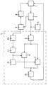
- the block diagram now shows the essential modules required for correcting the misalignment.
- the correction can be carried out manually or automatically using controlled actuators respectively.
- the correction values of the control signals for the actuators are then written into suitable memories and are therefore available for the operating time of the playback device with this scanning head. After repairs to the readhead, the memory values must be reset.
- the scanning head 1 supplies an output signal which is modulated at high frequency with the read information, which is amplified by a preamplifier 2 and processed further in the data decoder 3.
- the output signal of the preamplifier 2 is further amplified in a measuring stage 4 in an amplifier 5, which may show a low-pass behavior, and then fed as an input signal to two synchronous demodulators 6, 7 connected in parallel.
- the preamplifier 2 has a second signal output to which the focus servo 8 is connected.
- This focus servo 8 delivers a signal with which the scanning head is kept at a constant distance from the disk surface by means of the focus actuator 9. In the case of a storage disk with a vertical disk blow, the signal is superimposed on the AC voltage already mentioned.
- This AC voltage is fed via a low-pass filter 10 and a limiter amplifier 11 directly to the control input of the first synchronous demodulator 6 and to the control input of the second synchronous demodulator 7 via a 90 ° phase shifter 12.
- the output voltages of the two synchronous demodulators now correspond to two components of the misalignment which are offset by 90 ° from one another.
- an evaluation circuit 13 can be used to perform two swivel movements offset by 90 ° control in the bearing of the scanning head so that both components are at a minimum. These pivotal movements can, for. B. by 90 ° offset piezo elements in the bearing of the lens. If the correction value, ie the control voltages for the piezo elements, is stored, the measuring stage 4 can be set up as a separate part for the setting of the micro elements.
- the playback device must be equipped with an externally accessible tap for the RF-modulated output signal of the preamplifier and for the control signal for the focus actuator.
- the two output voltages can be displayed on a screen, where the minimization can be followed optically.
- the correction is expediently carried out in an iterative way, the direction of action of an adjustment made being checked.
- pivoting movements can, for. B. also be caused by 90 ° offset piezo elements in the bearing of the drive motor.
- One of the piezo elements is expediently arranged in one plane with the scanning head.
Landscapes
- Optical Recording Or Reproduction (AREA)
- Moving Of The Head For Recording And Reproducing By Optical Means (AREA)
Applications Claiming Priority (4)
| Application Number | Priority Date | Filing Date | Title |
|---|---|---|---|
| DE4103506 | 1991-02-06 | ||
| DE4103506 | 1991-02-06 | ||
| DE4103949 | 1991-02-09 | ||
| DE19914103949 DE4103949A1 (de) | 1991-02-09 | 1991-02-09 | Verfahren zur korrektur eines fehlwinkels in einem cd-player |
Publications (3)
| Publication Number | Publication Date |
|---|---|
| EP0498246A2 true EP0498246A2 (fr) | 1992-08-12 |
| EP0498246A3 EP0498246A3 (en) | 1993-03-03 |
| EP0498246B1 EP0498246B1 (fr) | 1997-01-02 |
Family
ID=25900792
Family Applications (1)
| Application Number | Title | Priority Date | Filing Date |
|---|---|---|---|
| EP92101241A Expired - Lifetime EP0498246B1 (fr) | 1991-02-06 | 1992-01-27 | Méthode pour la correction d'une erreur d'angle |
Country Status (4)
| Country | Link |
|---|---|
| EP (1) | EP0498246B1 (fr) |
| JP (1) | JPH04315824A (fr) |
| DE (1) | DE59207786D1 (fr) |
| ES (1) | ES2095965T3 (fr) |
Cited By (1)
| Publication number | Priority date | Publication date | Assignee | Title |
|---|---|---|---|---|
| CN1306500C (zh) * | 2004-02-12 | 2007-03-21 | 三洋电机株式会社 | 信息记录再生装置 |
Families Citing this family (1)
| Publication number | Priority date | Publication date | Assignee | Title |
|---|---|---|---|---|
| US6904177B2 (en) * | 2001-03-13 | 2005-06-07 | Canon Kabushiki Kaisha | Filter processing apparatus |
Family Cites Families (4)
| Publication number | Priority date | Publication date | Assignee | Title |
|---|---|---|---|---|
| JPS5911543A (ja) * | 1982-07-10 | 1984-01-21 | Sony Corp | 光学式デイスク再生装置 |
| JPS60143448A (ja) * | 1983-12-29 | 1985-07-29 | Sony Corp | スキユ−エラ−検出回路 |
| JP2911449B2 (ja) * | 1987-10-29 | 1999-06-23 | パイオニア株式会社 | 光学式情報読取装置 |
| JP2572842B2 (ja) * | 1989-05-10 | 1997-01-16 | パイオニア株式会社 | 光学的読取り信号のクロストーク量検出装置 |
-
1992
- 1992-01-27 EP EP92101241A patent/EP0498246B1/fr not_active Expired - Lifetime
- 1992-01-27 ES ES92101241T patent/ES2095965T3/es not_active Expired - Lifetime
- 1992-01-27 DE DE59207786T patent/DE59207786D1/de not_active Expired - Fee Related
- 1992-02-04 JP JP4018836A patent/JPH04315824A/ja active Pending
Cited By (1)
| Publication number | Priority date | Publication date | Assignee | Title |
|---|---|---|---|---|
| CN1306500C (zh) * | 2004-02-12 | 2007-03-21 | 三洋电机株式会社 | 信息记录再生装置 |
Also Published As
| Publication number | Publication date |
|---|---|
| DE59207786D1 (de) | 1997-02-13 |
| JPH04315824A (ja) | 1992-11-06 |
| ES2095965T3 (es) | 1997-03-01 |
| EP0498246B1 (fr) | 1997-01-02 |
| EP0498246A3 (en) | 1993-03-03 |
Similar Documents
| Publication | Publication Date | Title |
|---|---|---|
| DE3346114C2 (de) | Optisches Plattengerät | |
| DE3545996C2 (fr) | ||
| DE2935250C2 (de) | Spurführungs-Steuereinrichtung für den Abtastlichtstrahl einer optischen Leseeinrichtung | |
| DE69807112T2 (de) | Optisches servosystem für bandantrieb | |
| DE69030017T2 (de) | Optischer Plattenantrieb | |
| DE69624763T2 (de) | Verfahren und Gerät zum Abtasten einer mehrschichtigen Platte | |
| DE3409588C2 (de) | Servosystem für die Spurverfolgung und/oder Fokussierung in einem Datenlesegerät | |
| DE2353127B2 (de) | Video-plattenspieler | |
| DE3602640A1 (de) | Optisches informations- aufzeichnungs-/wiedergabesystem | |
| DE69617799T2 (de) | Vorrichtung und Verfahren zur optischen Aufzeichnung/Wiedergabe von Informationen | |
| DE3887601T2 (de) | Informationsaufnahme- und/oder -wiedergabegerät mit Mitteln zur Feststellung aller Spurfolgefehler. | |
| DE69019248T2 (de) | Optisches Aufnahme- und/oder Wiedergabegerät. | |
| DE3730555C2 (fr) | ||
| DE19515206A1 (de) | Verfahren und Apparat zur Fokussierungsregelung | |
| DE3873005T2 (de) | Optischer plattenspieler. | |
| DE68916273T2 (de) | Optisches Aufnahme/Wiedergabegerät. | |
| DE3831923A1 (de) | Optisches geraet zum fokussieren eines lichtstrahls auf ein objekt fuer datenaufzeichnung | |
| DE3501609C2 (fr) | ||
| DE3503117A1 (de) | Abspielgeraet fuer aufgezeichnete daten | |
| EP0681290B1 (fr) | Dispositif de balayage avec adaptation | |
| DE68912149T2 (de) | Optisches Informationsverarbeitungsgerät. | |
| DE2607275C3 (de) | Lichtstrahl-Abtasteinrichtung | |
| EP0498246A2 (fr) | Méthode pour la correction d'une erreur d'angle | |
| DE69114433T2 (de) | Optische Platteneinheit. | |
| DE3612829C2 (fr) |
Legal Events
| Date | Code | Title | Description |
|---|---|---|---|
| PUAI | Public reference made under article 153(3) epc to a published international application that has entered the european phase |
Free format text: ORIGINAL CODE: 0009012 |
|
| AK | Designated contracting states |
Kind code of ref document: A2 Designated state(s): DE ES FR IT |
|
| PUAL | Search report despatched |
Free format text: ORIGINAL CODE: 0009013 |
|
| AK | Designated contracting states |
Kind code of ref document: A3 Designated state(s): DE ES FR IT |
|
| 17P | Request for examination filed |
Effective date: 19930812 |
|
| 17Q | First examination report despatched |
Effective date: 19950814 |
|
| GRAG | Despatch of communication of intention to grant |
Free format text: ORIGINAL CODE: EPIDOS AGRA |
|
| GRAH | Despatch of communication of intention to grant a patent |
Free format text: ORIGINAL CODE: EPIDOS IGRA |
|
| GRAH | Despatch of communication of intention to grant a patent |
Free format text: ORIGINAL CODE: EPIDOS IGRA |
|
| GRAA | (expected) grant |
Free format text: ORIGINAL CODE: 0009210 |
|
| AK | Designated contracting states |
Kind code of ref document: B1 Designated state(s): DE ES FR IT |
|
| ET | Fr: translation filed | ||
| REF | Corresponds to: |
Ref document number: 59207786 Country of ref document: DE Date of ref document: 19970213 |
|
| REG | Reference to a national code |
Ref country code: ES Ref legal event code: FG2A Ref document number: 2095965 Country of ref document: ES Kind code of ref document: T3 |
|
| ITF | It: translation for a ep patent filed | ||
| PLBE | No opposition filed within time limit |
Free format text: ORIGINAL CODE: 0009261 |
|
| STAA | Information on the status of an ep patent application or granted ep patent |
Free format text: STATUS: NO OPPOSITION FILED WITHIN TIME LIMIT |
|
| 26N | No opposition filed | ||
| PGFP | Annual fee paid to national office [announced via postgrant information from national office to epo] |
Ref country code: DE Payment date: 20070313 Year of fee payment: 16 |
|
| PGFP | Annual fee paid to national office [announced via postgrant information from national office to epo] |
Ref country code: ES Payment date: 20080125 Year of fee payment: 17 |
|
| PGFP | Annual fee paid to national office [announced via postgrant information from national office to epo] |
Ref country code: IT Payment date: 20080124 Year of fee payment: 17 |
|
| PGFP | Annual fee paid to national office [announced via postgrant information from national office to epo] |
Ref country code: FR Payment date: 20080118 Year of fee payment: 17 |
|
| PG25 | Lapsed in a contracting state [announced via postgrant information from national office to epo] |
Ref country code: DE Free format text: LAPSE BECAUSE OF NON-PAYMENT OF DUE FEES Effective date: 20080801 |
|
| REG | Reference to a national code |
Ref country code: FR Ref legal event code: ST Effective date: 20091030 |
|
| REG | Reference to a national code |
Ref country code: ES Ref legal event code: FD2A Effective date: 20090128 |
|
| PG25 | Lapsed in a contracting state [announced via postgrant information from national office to epo] |
Ref country code: FR Free format text: LAPSE BECAUSE OF NON-PAYMENT OF DUE FEES Effective date: 20090202 Ref country code: ES Free format text: LAPSE BECAUSE OF NON-PAYMENT OF DUE FEES Effective date: 20090128 |
|
| PG25 | Lapsed in a contracting state [announced via postgrant information from national office to epo] |
Ref country code: IT Free format text: LAPSE BECAUSE OF NON-PAYMENT OF DUE FEES Effective date: 20090127 |