EP0498362A2 - Ein Bandaufnahmegerät - Google Patents
Ein Bandaufnahmegerät Download PDFInfo
- Publication number
- EP0498362A2 EP0498362A2 EP92101801A EP92101801A EP0498362A2 EP 0498362 A2 EP0498362 A2 EP 0498362A2 EP 92101801 A EP92101801 A EP 92101801A EP 92101801 A EP92101801 A EP 92101801A EP 0498362 A2 EP0498362 A2 EP 0498362A2
- Authority
- EP
- European Patent Office
- Prior art keywords
- cassette
- tape
- shutter
- pressing
- magnetic head
- Prior art date
- Legal status (The legal status is an assumption and is not a legal conclusion. Google has not performed a legal analysis and makes no representation as to the accuracy of the status listed.)
- Withdrawn
Links
Images


Classifications
-
- G—PHYSICS
- G11—INFORMATION STORAGE
- G11B—INFORMATION STORAGE BASED ON RELATIVE MOVEMENT BETWEEN RECORD CARRIER AND TRANSDUCER
- G11B15/00—Driving, starting or stopping record carriers of filamentary or web form; Driving both such record carriers and heads; Guiding such record carriers or containers therefor; Control thereof; Control of operating function
- G11B15/60—Guiding record carrier
-
- G—PHYSICS
- G11—INFORMATION STORAGE
- G11B—INFORMATION STORAGE BASED ON RELATIVE MOVEMENT BETWEEN RECORD CARRIER AND TRANSDUCER
- G11B25/00—Apparatus characterised by the shape of record carrier employed but not specific to the method of recording or reproducing, e.g. dictating apparatus; Combinations of such apparatus
- G11B25/06—Apparatus characterised by the shape of record carrier employed but not specific to the method of recording or reproducing, e.g. dictating apparatus; Combinations of such apparatus using web-form record carriers, e.g. tape
- G11B25/063—Apparatus characterised by the shape of record carrier employed but not specific to the method of recording or reproducing, e.g. dictating apparatus; Combinations of such apparatus using web-form record carriers, e.g. tape using tape inside container
-
- G—PHYSICS
- G11—INFORMATION STORAGE
- G11B—INFORMATION STORAGE BASED ON RELATIVE MOVEMENT BETWEEN RECORD CARRIER AND TRANSDUCER
- G11B15/00—Driving, starting or stopping record carriers of filamentary or web form; Driving both such record carriers and heads; Guiding such record carriers or containers therefor; Control thereof; Control of operating function
- G11B15/675—Guiding containers, e.g. loading, ejecting cassettes
- G11B15/67581—Guiding containers, e.g. loading, ejecting cassettes with pivoting movement of the cassette holder
- G11B15/67584—Guiding containers, e.g. loading, ejecting cassettes with pivoting movement of the cassette holder outside the apparatus
Definitions
- the present invention relates to a tape recorder, and more particularly to a tape recorder for allowing the use of two types of tape cassettes, one having front windows being closable with a shutter when the cassette is not used and openable when used, and the other type having a thick portion in the front openings for allowing a magnetic head, pinch rollers and the like to be inserted.
- High fidelity tape recorders are becoming popular which are digital recording and digital playback systems, among which an R-DAT system utilizing a rotatable head and an S-DAT system utilizing a fixed head are known.
- the S-DAT system is especially popular because of the similar structures of the head and the tape cassette with those of an analog tape recorder currently in wide use.
- the proposed tape recorder with the analog and digital feasibilities mentioned above allows two types of tape cassettes to be installed, wherein the two types are an analog compact cassette (hereinafter called the ACC) having a thick portion in the front openings for allowing a magnetic head, pinch rollers and the like to be inserted, and a digital compact cassette (hereinafter called the DCC) with a shutter, having front openings for allowing a magnetic head, pinch rollers and the like to be inserted, the openings being closable when the cassette is not used, and openable when used.
- This type of tape recorder can be applied both to the DCC with a shutter and to the conventional ACC.
- the tape recorder of this invention which overcomes the above-discussed and numerous other disadvantages and deficiencies of the prior art, comprises a first position where an analog compact cassette and a digital tape cassette are installed and dismounted, and a second position where a magnetic tape is caused to run, wherein the digital tape cassette has a shutter for covering front openings for inserting a magnetic head and pinch rollers when the cassette is not used and opened in the magnetic tape play or rewind directions when the cassette is used, and a holding means for allowing either type of cassette to reciprocate between the first position and the second position, and a shutter operating means for opening and closing the shutter of the digital type of cassette, wherein the holding means is integrated with the shutter operating means.
- the arm member rotates beyond a position where the shutter of the cassette is opened at a cassette installing position up to a position forward of the front surface of the tape cassette installed on the holder.
- the arm member comprises an engager having a thicker portion than one type of tape cassettes at least in a position where a magnetic head, pinch rollers and the like are inserted, the thicker portion having a thickness sufficient to enable the engager to be engageable with the front part of the other type of cassette.
- the tape recorder is applicable to an analog type compact cassette and a digital type tape cassette with a shutter, and comprises a cassette pressing member for pressing the tape cassettes toward a magnetic head thereof, an obstructive member for preventing the tape cassette from moving toward the magnetic head by the cassette pressing means so as to exactly locate the tape cassette at an installing position, the cassette pressing member having a reverse V-shaped elastic part with its one end fixed on a lower base plate and the other end being displaceable, a first pressing portion for pressing one side of a positioning hole of the digital type tape cassette, and opening the shutter in a magnetic tape running direction or in the opposite direction when the cassette is used, and a second pressing portion for pressing one side of a positioning hole of the analog type tape cassette having a thicker portion including front openings for inserting a magnetic head, pinch rollers and the like than that of the digital type tape cassette.
- the invention described herein makes possible the objective of providing a tape recorder applicable to both the ACC and the DCC equipped with a shutter which is easily opened when the DCC is installed.
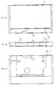
- the reference numeral 1 denotes a DCC equipped with a shutter, the DDC being of about the same size as an ACC.
- the DDC includes windows 1a , 1b and 1c in the front surface for inserting a magnetic head 2 , and a first and a second pinch rollers 3 and 4 , respectively, closable by a shutter 1d as shown in Figure 8A when the DDC is not used.
- the shutter 1d is slid in a tape play direction or a tape rewind direction so as to open the windows 1a , 1b and 1c .
- the DCC 1 also includes a guide portion 1j , a lock portion 1k and a notch 1l .
- a first and a second positioning hole 1e and 1f provided on the back side of the DCC 1 are also openable when the shutter 1d is slid.
- the reference numeral 7 denotes a lower base plate provided along the inlet portion 6b fixed on the upper base plate 5 by screws (not shown) with a space therebetween.
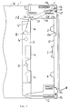
- the reference numerals 8 and 9 denote a first and second cassette holder supports fixed on the upper base plate 5 , which support a holder 10 rotatably on their axes 8a and 9a as shown in Figure 5 .
- the holder 10 is fixed at both ends by screws (not shown), and includes a first and second cassette holders 11 and 12 for accommodating tape cassettes.
- the first and second pinch rollers 3 and 4 are carried on the axes of a first and second pinch roller arms (not shown) upright on the holder 10 . These pinch rollers 3 and 4 are loaded in clockwise and counterclockwise directions (in Figure 1 ) by a first and a second spring around the pinch roller arms.
- the reference numeral 13 denotes a shutter operating means for sliding the shutter 1d of the DCC 1 for opening and closing.
- the shutter operating means 13 includes an arm member 13b whose base end 13a is rotatably fixed to an axis by the holder 10 , and a spring 14 which presses the arm member 13b toward the axis in a clockwise direction (in Figure 1 ).
- the shutter operating means 13 is slidably inserted between the first cassette holder 11 and the holder 10 , and is biased toward the axis and pressed against the inner surface of the first cassette holder 11 by the spring 14 .
- the shutter operating means 13 is slid to open the shutter 1d with an end portion 13c of the arm member 13b riding on the shutter 1d against the spring 14 and other spring (not shown) provided in the DCC 1 for closing the shutter in accordance with the depth of insertion of the DCC 1 .
- the spring 14 is brought into engagement with a groove wall 15 of the holder 10 and a projection 13d on the side of the base end of the arm member 13b at one end 14a and at the opposite end 14b , respectively, thereby pressing the arm member 13b in a clockwise direction in Figure 1 .
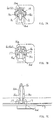
- the arm member 13b rotates about the base end 13a beyond the position shown in Figure 3 and up to a further position forward of the front surface of the DCC 1 at the installing position.
- a housing 10a is provided on the holder 10 to prevent the arm member 13b from abutting against the holder 10 , thereby preventing the shutter operating means 13 from being damaged when the DCC 1 is inadvertently inserted inside out, pressed by fingers, or the like.
- the arm member 13b has an engager 13e designed to rotate against the spring 14 in accordance with the amount of insertion of the ACC 6 shown in Figure 4 instead of the DCC 1 .
- the engager 13e comes into engagement with the front surface of the inlet portion 6b so that the arm member 13 can be accommodated in the housing 10a of the holder 10 .
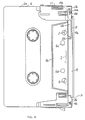
- the reference numeral 16 denotes a pair of cassette pressing members for pressing the DCC 1 or the ACC 6 toward the magnetic head.
- One end 16a of the cassette pressing member 16 is fixed on the lower base plate 7 , and the other end 16b is made of an elastic material in a reverse V-shape so as to be displaceable.
- the cassette pressing member 16 includes a first pressing portion 16c for pressing front curving portions 1h and 1i of the DCC 1 when it is inserted into the first and the second positioning holes 1e and 1f having continuously curved portions.
- the cassette pressing member 16 also includes a second pressing portion 16d for pressing front portions 1h and 1i of the ACC 6 which is provided with positioning virtually round holes 6c and 6d .
- the DCC 1 and ACC 6 are positioned in the left-hand and right-hand directions as follows:
- the DCC 1 When the holder 10 is rotated about the axes 8a and 9a from the conditions shown in Figures 3 and 5 , the DCC 1 is brought into the position shown in Figure 6A . In this position, the cassette pressing member 16 is yieldingly inserted into the first and the second positioning holes 1e and 1f . The position of the DCC 1 toward the magnetic head and in the traverse direction is restrained by the first pressing portion 16c , the end 16a , and the first and the second obstructive portions 18a and 18b , thereby fixing the DCC 1 at the installing position.
- the operation of the tape recorder when using the ACC 6 is as follows: The procedure is almost the same as that taken when the DCC 1 is used, except that the arm member 13b is accommodated in the housing 10a of the holder 10 with its engager 13e touching the front surface of the inlet portion 6b of the ACC 6 as shown in Figure 4 . Another difference is that the ACC 6 is positioned by the second pressing portion 16d of the cassette pressing member 16 inserted into the first and the second positioning holes 6c and 6d , the positioning member 17 inserted into the first positioning hole 6c and the first and the third obstructive portions 18a and 18c .
- the tape recorder has a holder means capable of reciprocating between the first position where the tape cassette with a shutter is removed and the second position where the magnetic tape is caused to run, the holder means being integrated with the shutter operating means for opening/closing which is constructed with the arm member, thereby ensuring the shutter operating and reducing the size of the tape recorder.
- the installed tape cassette can rotate beyond the position where the shutter is opened, until it reaches a position forward of the front surface of the tape cassette. Therefore, the shutter operating means is protected from being damaged even when the tape cassette is erroneously inserted.
- the arm member functioning as the shutter operating means provided with a thicker portion in the opening for allowing the insertion of the magnetic head and the like than that of the DCC is rotated beyond the front surface of the tape cassette, no obstruction acts upon the insertion of them, thereby enabling the tape recorder to be applied to ACCs.
- the cassette pressing member for pressing the tape cassette toward the magnetic head is provided with the first pressing portion for pressing one side of the positioning hole of the DCC and the second pressing portion for pressing the other side of the positioning hole of the ACC. Therefore, the tape cassette is exactly and firmly positioned in the tape recorder.
Landscapes
- Feeding And Guiding Record Carriers (AREA)
- Recording Or Reproducing By Magnetic Means (AREA)
- Adjustment Of The Magnetic Head Position Track Following On Tapes (AREA)
- Magnetic Heads (AREA)
Applications Claiming Priority (2)
| Application Number | Priority Date | Filing Date | Title |
|---|---|---|---|
| JP14263/91 | 1991-02-05 | ||
| JP3014263A JPH04254950A (ja) | 1991-02-05 | 1991-02-05 | テープレコーダ |
Publications (2)
| Publication Number | Publication Date |
|---|---|
| EP0498362A2 true EP0498362A2 (de) | 1992-08-12 |
| EP0498362A3 EP0498362A3 (en) | 1994-05-11 |
Family
ID=11856207
Family Applications (1)
| Application Number | Title | Priority Date | Filing Date |
|---|---|---|---|
| EP19920101801 Withdrawn EP0498362A3 (en) | 1991-02-05 | 1992-02-04 | A tape recorder |
Country Status (4)
| Country | Link |
|---|---|
| US (1) | US5483395A (de) |
| EP (1) | EP0498362A3 (de) |
| JP (1) | JPH04254950A (de) |
| KR (1) | KR960003490B1 (de) |
Cited By (1)
| Publication number | Priority date | Publication date | Assignee | Title |
|---|---|---|---|---|
| US5406430A (en) * | 1991-08-29 | 1995-04-11 | Matsushita Electric Industrial Co., Ltd. | Cassette tape mount for use in a cassette tape recorder |
Families Citing this family (2)
| Publication number | Priority date | Publication date | Assignee | Title |
|---|---|---|---|---|
| JPH05182313A (ja) * | 1991-12-27 | 1993-07-23 | Matsushita Electric Ind Co Ltd | テープレコーダ |
| US5724206A (en) * | 1995-09-14 | 1998-03-03 | Industrial Technology Research Institute | Protective cover opening mechanism for a cassett loading and unloading apparatus for cassette recorders |
Family Cites Families (14)
| Publication number | Priority date | Publication date | Assignee | Title |
|---|---|---|---|---|
| US4097006A (en) * | 1975-08-11 | 1978-06-27 | Olympus Optical Co., Ltd. | Magnetic tape cassette |
| US4620254A (en) * | 1983-01-04 | 1986-10-28 | Bsr North America, Ltd. | Information storage and retrieval system including a tape cartridge having a slidable cover |
| JPS6051682U (ja) * | 1983-09-16 | 1985-04-11 | 富士写真フイルム株式会社 | 磁気テ−プカセツト |
| US4607303A (en) * | 1983-12-27 | 1986-08-19 | Minnesota Mining And Manufacturing Company | Tripod cassette positioning |
| JPH07122981B2 (ja) * | 1985-09-03 | 1995-12-25 | ソニー株式会社 | カセツトテ−プレコ−ダ |
| JPH0640413B2 (ja) * | 1985-09-23 | 1994-05-25 | ソニー株式会社 | デイスクカ−トリツジのシヤツタ開閉機構 |
| KR910000369B1 (ko) * | 1985-11-01 | 1991-01-24 | 마쯔시다덴기산교 가부시기가이샤 | 전자스틸카메라의 기록장치 |
| GB2187879B (en) * | 1986-03-11 | 1990-04-11 | Mitsubishi Electric Corp | Cassette recording and/or reproducing apparatus |
| JPH0731853B2 (ja) * | 1987-07-01 | 1995-04-10 | 松下電器産業株式会社 | カセット装填装置 |
| US4918552A (en) * | 1987-09-10 | 1990-04-17 | Pioneer Electronic Corporation | Cassette tape recorder having means for preventing cassette vibration during playback/recording |
| YU123090A (sh) * | 1989-07-03 | 1994-04-05 | N.V. Philips Gloelampenfabrieken | Sistem za snemanje/reprodukcijo signalov na/s magnetnega traku v kaseti |
| US5365393A (en) * | 1989-12-18 | 1994-11-15 | U.S. Philips Corporation | Magnetic tape cassette having a groove extending perpendicular to a front wall thereof for engagement by a loading mechanism of a tape cassette apparatus |
| US5161079A (en) * | 1990-01-19 | 1992-11-03 | Matsushita Electric Industrial Co., Ltd. | Tape cassette with slidable shutter |
| JPH1010456A (ja) * | 1996-06-19 | 1998-01-16 | Canon Inc | 画像形成装置 |
-
1991
- 1991-02-05 JP JP3014263A patent/JPH04254950A/ja active Pending
-
1992
- 1992-02-01 KR KR1019920001609A patent/KR960003490B1/ko not_active Expired - Fee Related
- 1992-02-04 EP EP19920101801 patent/EP0498362A3/en not_active Withdrawn
-
1994
- 1994-04-20 US US08/231,584 patent/US5483395A/en not_active Expired - Fee Related
Cited By (1)
| Publication number | Priority date | Publication date | Assignee | Title |
|---|---|---|---|---|
| US5406430A (en) * | 1991-08-29 | 1995-04-11 | Matsushita Electric Industrial Co., Ltd. | Cassette tape mount for use in a cassette tape recorder |
Also Published As
| Publication number | Publication date |
|---|---|
| KR960003490B1 (ko) | 1996-03-14 |
| US5483395A (en) | 1996-01-09 |
| JPH04254950A (ja) | 1992-09-10 |
| EP0498362A3 (en) | 1994-05-11 |
| KR920017056A (ko) | 1992-09-26 |
Similar Documents
| Publication | Publication Date | Title |
|---|---|---|
| EP0219980B1 (de) | Vorrichtung zum Öffnen und Schliessen einer Verschlussvorrichtung einer Plattenkassette | |
| EP0163549B1 (de) | Bandkassettenaufzeichnungs- und/oder Wiedergabegerät | |
| KR900008097B1 (ko) | 테이프 카세트 | |
| GB2124012A (en) | Disc cassette loading apparatus | |
| US4323207A (en) | Latch assembly for a video tape cassette | |
| EP0444623B1 (de) | Bandkassette-Lademechanismus | |
| US4408733A (en) | Magnetic tape cassette | |
| US4703384A (en) | Magnetic tape cassette with reel-lock mechanism | |
| US5483395A (en) | Tape recorder for use with analog compact cassettes and digital tape cassettes | |
| EP0549355A2 (de) | Vorrichtung zur Bandsortenidentifizierung einer in einem Bandaufzeichnungsgerät eingeschobenen und montierten Bandkassette | |
| EP0628962A2 (de) | Kassettenbandwiedergabegerät mit Kassettenführung | |
| US5406430A (en) | Cassette tape mount for use in a cassette tape recorder | |
| JPH0753165Y2 (ja) | 記録再生カセットの挿入装置 | |
| JPS5914951Y2 (ja) | ビデオテ−プカセツト | |
| JPS6037743Y2 (ja) | カセツト閉蓋ロツク解除機構 | |
| EP0530700A2 (de) | Kassettenbandladevorrichtung zum Gebrauch in einem Kassettenbandaufzeichnungsgerät | |
| JPS6017114Y2 (ja) | テ−プカセツト | |
| JPH0562311A (ja) | テープレコーダ | |
| JP2629431B2 (ja) | テープカセット | |
| JPS5935900Y2 (ja) | テ−プカセツト | |
| JPH0525109Y2 (de) | ||
| JP3227951B2 (ja) | テープカセット | |
| JPH04274071A (ja) | 磁気テープカセット | |
| JP2616514B2 (ja) | テープカセット | |
| JPH06180911A (ja) | テープレコーダー |
Legal Events
| Date | Code | Title | Description |
|---|---|---|---|
| PUAI | Public reference made under article 153(3) epc to a published international application that has entered the european phase |
Free format text: ORIGINAL CODE: 0009012 |
|
| 17P | Request for examination filed |
Effective date: 19920204 |
|
| AK | Designated contracting states |
Kind code of ref document: A2 Designated state(s): DE GB |
|
| PUAL | Search report despatched |
Free format text: ORIGINAL CODE: 0009013 |
|
| AK | Designated contracting states |
Kind code of ref document: A3 Designated state(s): DE GB |
|
| 17Q | First examination report despatched |
Effective date: 19941122 |
|
| STAA | Information on the status of an ep patent application or granted ep patent |
Free format text: STATUS: THE APPLICATION IS DEEMED TO BE WITHDRAWN |
|
| 18D | Application deemed to be withdrawn |
Effective date: 19960829 |