EP0498378A2 - Verbrennung mit kohärentem Strahl - Google Patents
Verbrennung mit kohärentem Strahl Download PDFInfo
- Publication number
- EP0498378A2 EP0498378A2 EP92101843A EP92101843A EP0498378A2 EP 0498378 A2 EP0498378 A2 EP 0498378A2 EP 92101843 A EP92101843 A EP 92101843A EP 92101843 A EP92101843 A EP 92101843A EP 0498378 A2 EP0498378 A2 EP 0498378A2
- Authority
- EP
- European Patent Office
- Prior art keywords
- cavity
- oxidant
- main
- burner
- fuel
- Prior art date
- Legal status (The legal status is an assumption and is not a legal conclusion. Google has not performed a legal analysis and makes no representation as to the accuracy of the status listed.)
- Granted
Links
- 238000002485 combustion reaction Methods 0.000 title claims abstract description 48
- 230000001427 coherent effect Effects 0.000 title claims abstract description 13
- 239000007800 oxidant agent Substances 0.000 claims abstract description 102
- 230000001590 oxidative effect Effects 0.000 claims abstract description 102
- 239000000446 fuel Substances 0.000 claims description 31
- QVGXLLKOCUKJST-UHFFFAOYSA-N atomic oxygen Chemical compound [O] QVGXLLKOCUKJST-UHFFFAOYSA-N 0.000 claims description 14
- 239000001301 oxygen Substances 0.000 claims description 14
- 229910052760 oxygen Inorganic materials 0.000 claims description 14
- 238000000034 method Methods 0.000 claims description 13
- MYMOFIZGZYHOMD-UHFFFAOYSA-N Dioxygen Chemical compound O=O MYMOFIZGZYHOMD-UHFFFAOYSA-N 0.000 claims description 3
- 238000010304 firing Methods 0.000 claims description 3
- 238000002347 injection Methods 0.000 claims description 3
- 239000007924 injection Substances 0.000 claims description 3
- 238000011144 upstream manufacturing Methods 0.000 claims description 3
- XLYOFNOQVPJJNP-UHFFFAOYSA-N water Substances O XLYOFNOQVPJJNP-UHFFFAOYSA-N 0.000 abstract description 12
- 238000001816 cooling Methods 0.000 abstract description 8
- 238000009841 combustion method Methods 0.000 abstract description 5
- 239000007789 gas Substances 0.000 description 13
- VNWKTOKETHGBQD-UHFFFAOYSA-N methane Chemical compound C VNWKTOKETHGBQD-UHFFFAOYSA-N 0.000 description 6
- 239000002826 coolant Substances 0.000 description 5
- ATUOYWHBWRKTHZ-UHFFFAOYSA-N Propane Chemical compound CCC ATUOYWHBWRKTHZ-UHFFFAOYSA-N 0.000 description 2
- 239000003345 natural gas Substances 0.000 description 2
- 238000013021 overheating Methods 0.000 description 2
- 230000001154 acute effect Effects 0.000 description 1
- 239000000571 coke Substances 0.000 description 1
- 238000009833 condensation Methods 0.000 description 1
- 230000005494 condensation Effects 0.000 description 1
- 238000007796 conventional method Methods 0.000 description 1
- 230000007423 decrease Effects 0.000 description 1
- 238000013461 design Methods 0.000 description 1
- 239000007788 liquid Substances 0.000 description 1
- 238000002156 mixing Methods 0.000 description 1
- 239000000203 mixture Substances 0.000 description 1
- 239000001294 propane Substances 0.000 description 1
- 230000001681 protective effect Effects 0.000 description 1
- 230000005855 radiation Effects 0.000 description 1
- 229910001220 stainless steel Inorganic materials 0.000 description 1
- 239000010935 stainless steel Substances 0.000 description 1
- 238000012360 testing method Methods 0.000 description 1
- 238000012546 transfer Methods 0.000 description 1
Images

Classifications
-
- F—MECHANICAL ENGINEERING; LIGHTING; HEATING; WEAPONS; BLASTING
- F23—COMBUSTION APPARATUS; COMBUSTION PROCESSES
- F23D—BURNERS
- F23D14/00—Burners for combustion of a gas, e.g. of a gas stored under pressure as a liquid
- F23D14/32—Burners for combustion of a gas, e.g. of a gas stored under pressure as a liquid using a mixture of gaseous fuel and pure oxygen or oxygen-enriched air
-
- F—MECHANICAL ENGINEERING; LIGHTING; HEATING; WEAPONS; BLASTING
- F23—COMBUSTION APPARATUS; COMBUSTION PROCESSES
- F23R—GENERATING COMBUSTION PRODUCTS OF HIGH PRESSURE OR HIGH VELOCITY, e.g. GAS-TURBINE COMBUSTION CHAMBERS
- F23R3/00—Continuous combustion chambers using liquid or gaseous fuel
- F23R3/02—Continuous combustion chambers using liquid or gaseous fuel characterised by the air-flow or gas-flow configuration
-
- F—MECHANICAL ENGINEERING; LIGHTING; HEATING; WEAPONS; BLASTING
- F23—COMBUSTION APPARATUS; COMBUSTION PROCESSES
- F23D—BURNERS
- F23D14/00—Burners for combustion of a gas, e.g. of a gas stored under pressure as a liquid
- F23D14/20—Non-premix gas burners, i.e. in which gaseous fuel is mixed with combustion air on arrival at the combustion zone
-
- Y—GENERAL TAGGING OF NEW TECHNOLOGICAL DEVELOPMENTS; GENERAL TAGGING OF CROSS-SECTIONAL TECHNOLOGIES SPANNING OVER SEVERAL SECTIONS OF THE IPC; TECHNICAL SUBJECTS COVERED BY FORMER USPC CROSS-REFERENCE ART COLLECTIONS [XRACs] AND DIGESTS
- Y02—TECHNOLOGIES OR APPLICATIONS FOR MITIGATION OR ADAPTATION AGAINST CLIMATE CHANGE
- Y02E—REDUCTION OF GREENHOUSE GAS [GHG] EMISSIONS, RELATED TO ENERGY GENERATION, TRANSMISSION OR DISTRIBUTION
- Y02E20/00—Combustion technologies with mitigation potential
- Y02E20/34—Indirect CO2mitigation, i.e. by acting on non CO2directly related matters of the process, e.g. pre-heating or heat recovery
Definitions
- the invention relates generally to the field of burners and combustion and is particularly advantageous for use with burners and combustion employing oxygen or oxygen-enriched air as the oxidant.
- One conventional method for reducing heat damage to a burner is to circulate a coolant such as water through the burner. While this method provides adequate cooling to the burner, it has several disadvantages. A supply of clean water is required at the requisite pressure and such a supply may not always be readily available without considerable effort and additional equipment. The burner design itself is considerably more complicated to accommodate the coolant passages. The cooled burner surface temperature may be low enough to cause condensation of furnace gases which may corrode the burner. Coolant leaks may develop within the burner which can cause damage to the burner or a shutdown of the combustion operation.
- One method for addressing this problem which has found use in industrial combustion operations comprises recessing the burner from the furnace or combustion zone.
- a burner is recessed within a cavity in the furnace wall. In this way less heat or energy from the combustion zone is radiated to the burner surface and thus a separate coolant is not needed. Heat transfer by radiation from the furnace decreases as the burner is withdrawn into the cavity.
- combustion may, and usually does, occur within the cavity thus generating heat close to the burner surface and thereby increasing the heat to the burner.
- a method for carrying out combustion comprising:
- Non-water-cooled combustion apparatus comprising:
- water cooling means the use of water or a water-containing liquid to cool a burner.
- the term "coherent” means the flow of gas with little or no entrainment of ambient gas into the flowing gas.
- jet means a stream of gas leaving a hole in a nozzle at a substantially high velocity.
- a conventional jet there is entrained into the jet a substantial amount of ambient gas due to turbulence at the jet-ambient gas interface causing the jet to expand as it flows from the nozzle.
- a coherent jet only a minimal amount of ambient gas is entrained into the jet and the jet expands very little as it flows from the nozzle face.
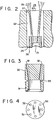
- Figure 1 is a cross-sectional representation of one preferred embodiment of the invention.
- Figure 2 is a simplified cross-sectional representation of the invention in operation.
- Figure 3 is a cross-sectional representation of one embodiment of a main oxidant nozzle useful with the invention.
- Figure 4 is a head-on view of the nozzle illustrated in Figure 3.
- the invention comprises, in general, the establishment and use of one or more high velocity coherent oxidant jets within a cavity recessed from a combustion zone which serve to retard combustion within the cavity but which serve to promote stable combustion upon passage from the cavity output end into the combustion zone.
- burner 1 comprises fuel tube 2 and oxidant provision means 3 which provide fuel and oxidant into walled cavity 4 which communicates at output end 5 with combustion zone 6.
- the fuel and oxidant may be provided into cavity 4 at its input end 7 as illustrated in Figure 1 or at any point within the walled cavity recessed from its output configuration.
- the walled cavity may have outwardly tapered walls 8 so that it is conical as illustrated in Figure 1 or may have straight walls so that it is cylindrical.
- the walled cavity is situated within refractory 9 which is generally part of a furnace wall.
- the burner 1 is secured to the refractory wall cavity by means of block plate 10 and flange 11.
- Fuel is provided into cavity 4 through outer annular passageway 12 and flows through cavity 4 near cavity wall 8 and then through output end 5 into combustion zone 6.
- the fuel is a gaseous fuel such as natural gas, methane, propane, or coke oven gas.
- Oxidant is provided into cavity 4 through oxidant provision means 3.
- the oxidant provision means comprises outer tube 13 containing screwable removable nozzle 14 which is slightly smaller than outer tube 13 so as to define an annular passageway 15.
- the end 16 of oxidant provision means 3 is recessed from the inlet end 17 of the cavity such as by the distance x illustrated in Figure 1.
- the distance x will vary depending upon the absolute size of the burner apparatus.
- the injection end of the burner may be upstream of or within the walled cavity.
- the end 18 of nozzle 14 is preferably recessed from end 16 by a distance y which may be within the range of from 0.125 to 0.5 inch.
- Nozzle 14 may have any effective configuration.
- nozzle 30 comprises threads 31 with which it may be inserted into the outer tube.
- Nozzle 30 also comprises a plurality of individual jet passages 32 through which oxidant is provided at a high velocity into the walled cavity.
- the nozzle illustrated in Figures 3 and 4 has eight such jet passages 32.
- Figure 4 illustrates a preferred arrangement wherein the jet passages are in a circular arrangement.
- Nozzle 30 also has annulus oxidant feed means 33 through which oxidant flows into the annular passageway.
- the oxidant may be any effective oxidant.
- the advantages attainable with this invention are most noticeable when the oxidant has an oxygen concentration of 30 percent or more.
- a particularly preferred oxidant is technically pure oxygen having an oxygen concentration of 99.5 percent or more.
- Main oxidant is provided into the walled cavity and flows therethrough at a high velocity.
- the velocity of the main oxidant is greater than 5P where P is the volume percent of oxygen in the main oxidant and the velocity is in feet per second (fps).
- the main oxidant velocity is at least 500 fps.
- the main oxidant is provided into walled cavity 4 as one or more high velocity jets through jet passages 19.
- the main oxidant is provided into and flows through the walled cavity as a plurality of jets.
- the jets will number generally within the range of from 1 to 16, preferably within the range of from 1 to 8.
- Secondary oxidant is provided into the walled cavity and flows therethrough at a velocity which is less than that of the main oxidant. Generally the velocity of the secondary oxidant is less than one half of the velocity of the main oxidant and preferably is less than 100 fps. The secondary oxidant will generally comprise from about 1 to 10 percent of the total oxidant provided into the walled cavity.
- Ignition of the combustible mixture may be attained by any convenient means.
- Figure 1 there is shown 20 the use of the igniter disclosed in U.S. Patent No. 4,892,475-Farrenkopf et al.as the means for igniting the combustion reaction.
- the high velocity main oxidant passes through the walled cavity as one or more high velocity jets while the lower velocity secondary oxidant flows through the walled cavity between the high velocity main oxidant and the fuel thus serving to maintain the flow of main oxidant substantially coherent as it flows through the walled cavity.
- the secondary oxidant due to its lower velocity mixes with and combusts with fuel within the cavity and this combustion forms a thin envelope around the high velocity oxidant. It is believed that if a combustion reaction is occurring at the main oxidant jet boundary, then the temperature will increase with a corresponding increase in gas volume. The gas at the interface will expand resulting in a velocity component in the radial direction. As the gas moves out radially, the turbulent boundary layer that is initiated at the high velocity - low velocity interface is continuously removed along the length of the jet in the same way as may happen with the use of suction for gas flow over a flat plate wherein the suction continuously removes the turbulent boundary layer and prevents it from growing. If the turbulent boundary layer is continuously removed for the length of the jet, entrainment will be minimized and the jet will be coherent.
- FIG. 2 illustrates in simplified form the operation of the invention to achieve coherent jet flow through the walled cavity.
- burner 21 is placed within walled cavity 22 and is recessed from the output end 23 of cavity 22 which communicates with combustion zone 24.
- Fuel is provided into cavity 22 through passage 25 and lower velocity secondary oxidant is provided into cavity 22 through annular passage 26.
- There is established within cavity 22 one or more coherent jets 27 of high velocity oxidant which pass through cavity 22 with minimal combustion of the high velocity main oxidant with the fuel.
- the combustion of the lower velocity secondary oxidant with the fuel results in a buffer layer of combustion products around the main oxidant.
- the consequent turbulence 28 causes the coherent jet or jets to break up resulting in rapid entrainment or mixing of the fuel with the oxidant resulting in effective stable combustion.
- the burner be as deeply recessed from the output end of the walled cavity as possible because the deeper the recession the greater is the protection of the burner from heat damage.
- the coherency of the high velocity main oxidant jet(s) may break down prior to their flow through the output end into the combustion zone resulting in significant combustion within the walled cavity with corresponding overheating. This defeats the purpose of the invention.
- the maximum length that the burner may be recessed will vary with each case depending on the absolute size of the burner apparatus.
- the cone half angle be less than 15 degrees.
- a burner of this invention was operated within a cylindrical cavity recessed from the cavity output end.
- the recess was varied from 1 to 8 inches.
- the oxidant employed was technically pure oxygen and the fuel was natural gas.
- the main oxidant velocity was greater than sonic velocity which is about 1000 fps and the secondary oxidant velocity was about 80 fps.
- the main oxidant comprised 8 high velocity jets.
- the burner was fired at a firing rate of 10 MM Btu/hr.
- a thermocouple was set in a stainless steel nozzle 1/8 inch back from the burner face.
- the burner was recessed in a cavity 4.5 inches in diameter. As the recess length was increased form 1 to 6 to 8 inches, the measured nozzle temperatures were 425°, 398°F and 412°F respectively.
- the oxygen jets were coherent within the cavity.
Landscapes
- Engineering & Computer Science (AREA)
- Chemical & Material Sciences (AREA)
- Combustion & Propulsion (AREA)
- Mechanical Engineering (AREA)
- General Engineering & Computer Science (AREA)
- Pre-Mixing And Non-Premixing Gas Burner (AREA)
- Nozzles For Spraying Of Liquid Fuel (AREA)
- Gas Burners (AREA)
Applications Claiming Priority (2)
| Application Number | Priority Date | Filing Date | Title |
|---|---|---|---|
| US07/650,852 US5100313A (en) | 1991-02-05 | 1991-02-05 | Coherent jet combustion |
| US650852 | 1991-02-05 |
Publications (3)
| Publication Number | Publication Date |
|---|---|
| EP0498378A2 true EP0498378A2 (de) | 1992-08-12 |
| EP0498378A3 EP0498378A3 (en) | 1993-01-07 |
| EP0498378B1 EP0498378B1 (de) | 1996-12-11 |
Family
ID=24610582
Family Applications (1)
| Application Number | Title | Priority Date | Filing Date |
|---|---|---|---|
| EP92101843A Expired - Lifetime EP0498378B1 (de) | 1991-02-05 | 1992-02-04 | Verbrennung mit kohärentem Strahl |
Country Status (9)
| Country | Link |
|---|---|
| US (1) | US5100313A (de) |
| EP (1) | EP0498378B1 (de) |
| JP (1) | JPH0566003A (de) |
| KR (1) | KR0150012B1 (de) |
| BR (1) | BR9200362A (de) |
| CA (1) | CA2060621C (de) |
| DE (1) | DE69215705T2 (de) |
| ES (1) | ES2095966T3 (de) |
| MX (1) | MX9200499A (de) |
Cited By (5)
| Publication number | Priority date | Publication date | Assignee | Title |
|---|---|---|---|---|
| EP1041341A1 (de) * | 1999-04-02 | 2000-10-04 | Praxair Technology, Inc. | Lanze mit kohärentem Mehrfachstrahl |
| EP1102003A1 (de) * | 1999-11-16 | 2001-05-23 | Praxair Technology, Inc. | System zur Bildung eines einzigen kohärenten Gasstrahl |
| EP1101064A4 (de) * | 1998-07-30 | 2001-11-07 | Bloom Eng Co Inc | Brenner für nicht-symmetrische verbrennung und verfahren dafür |
| US7175423B1 (en) | 2000-10-26 | 2007-02-13 | Bloom Engineering Company, Inc. | Air staged low-NOx burner |
| DE102011013950A1 (de) * | 2011-03-14 | 2012-09-20 | Air Liquide Deutschland Gmbh | Brenner und Verfahren zum Betreiben eines Brenners |
Families Citing this family (27)
| Publication number | Priority date | Publication date | Assignee | Title |
|---|---|---|---|---|
| US5209656A (en) * | 1991-08-29 | 1993-05-11 | Praxair Technology, Inc. | Combustion system for high velocity gas injection |
| US5256058A (en) * | 1992-03-30 | 1993-10-26 | Combustion Tec, Inc. | Method and apparatus for oxy-fuel heating with lowered NOx in high temperature corrosive environments |
| US5266025A (en) * | 1992-05-27 | 1993-11-30 | Praxair Technology, Inc. | Composite lance |
| US5267850A (en) * | 1992-06-04 | 1993-12-07 | Praxair Technology, Inc. | Fuel jet burner |
| US5266024A (en) * | 1992-09-28 | 1993-11-30 | Praxair Technology, Inc. | Thermal nozzle combustion method |
| US5449286A (en) * | 1993-06-22 | 1995-09-12 | Praxair Technology, Inc. | Controlled flame fuel jet combustion |
| KR100234570B1 (ko) * | 1993-08-31 | 1999-12-15 | 조안 엠. 젤사 | 아르곤과 산소를 이용한 연소방법 |
| US5439373A (en) * | 1993-09-13 | 1995-08-08 | Praxair Technology, Inc. | Luminous combustion system |
| FR2725017B1 (fr) * | 1994-09-22 | 1996-12-13 | Air Liquide | Ouvreau pour oxybruleur, ensemble d'oxybruleur comportant un tel ouvreau et procede de mise en oeuvre d'un tel ensemble |
| US5597298A (en) * | 1994-12-13 | 1997-01-28 | Praxair Technology, Inc. | Laminar flow burner |
| US5580237A (en) * | 1995-03-09 | 1996-12-03 | Praxair Technology, Inc. | Oxidant lancing nozzle |
| US5823762A (en) * | 1997-03-18 | 1998-10-20 | Praxair Technology, Inc. | Coherent gas jet |
| US5954498A (en) * | 1998-02-26 | 1999-09-21 | American Air Liquide, Inc. | Oxidizing oxygen-fuel burner firing for reducing NOx emissions from high temperature furnaces |
| US6176894B1 (en) | 1998-06-17 | 2001-01-23 | Praxair Technology, Inc. | Supersonic coherent gas jet for providing gas into a liquid |
| US7357636B2 (en) * | 2002-02-28 | 2008-04-15 | Align Technology, Inc. | Manipulable dental model system for fabrication of a dental appliance |
| US6241510B1 (en) | 2000-02-02 | 2001-06-05 | Praxair Technology, Inc. | System for providing proximate turbulent and coherent gas jets |
| US6250915B1 (en) | 2000-03-29 | 2001-06-26 | The Boc Group, Inc. | Burner and combustion method for heating surfaces susceptible to oxidation or reduction |
| US6254379B1 (en) * | 2000-09-27 | 2001-07-03 | Praxair Technology, Inc. | Reagent delivery system |
| US6432163B1 (en) | 2001-06-22 | 2002-08-13 | Praxair Technology, Inc. | Metal refining method using differing refining oxygen sequence |
| SE0501840L (sv) * | 2005-08-19 | 2007-02-20 | Aga Ab | Förfarande jämte för övervakning av en brännare |
| FR2903479A1 (fr) * | 2006-07-06 | 2008-01-11 | Air Liquide | Bruleur a flamme orientable et procede de mise en oeuvre |
| KR100805630B1 (ko) * | 2006-12-01 | 2008-02-20 | 주식회사 경동나비엔 | 가스보일러의 연소장치 |
| UA81737C2 (ru) * | 2007-04-24 | 2008-01-25 | Анатолий Тимофеевич Неклеса | Способ и печь для получения железа прямым восстановлением |
| FR2941286B1 (fr) * | 2009-01-16 | 2012-08-31 | Air Liquide | Bruleur pilote air-gaz pouvant fonctionner a l'oxygene. |
| US10429072B2 (en) | 2013-09-23 | 2019-10-01 | Bloom Engineering Company Inc. | Regenerative burner for non-symmetrical combustion |
| IT201900003481A1 (it) * | 2019-03-11 | 2020-09-11 | Sacmi Forni Spa | Apparato e bruciatore per la cottura di manufatti ceramici |
| EP4328487A1 (de) * | 2022-08-26 | 2024-02-28 | Sustainable Business & Engineering Solutions GmbH | Mehrrohrbrennersystem zur effizienten mischung von brennstoff und luft zur verbrennung |
Family Cites Families (14)
| Publication number | Priority date | Publication date | Assignee | Title |
|---|---|---|---|---|
| US3044539A (en) * | 1958-12-11 | 1962-07-17 | Eclipse Fuel Eng Co | Process of combustion |
| US3174527A (en) * | 1962-06-13 | 1965-03-23 | Zink Co John | Combination oil and/or gaseous fuel burner |
| US3861858A (en) * | 1972-12-11 | 1975-01-21 | Midland Ross Corp | Throat mix burner |
| RO60886A2 (de) * | 1974-03-21 | 1976-10-15 | ||
| DE2951796C2 (de) * | 1978-12-21 | 1982-11-04 | Kobe Steel, Ltd., Kobe, Hyogo | Brenner für gasförmige oder flüssige Brennstoffe für minimale NO↓x↓-Emission |
| JPS55155102A (en) * | 1979-05-18 | 1980-12-03 | Daido Steel Co Ltd | Low-nox oil burner |
| US4378205A (en) * | 1980-04-10 | 1983-03-29 | Union Carbide Corporation | Oxygen aspirator burner and process for firing a furnace |
| US4541796A (en) * | 1980-04-10 | 1985-09-17 | Union Carbide Corporation | Oxygen aspirator burner for firing a furnace |
| US4541798A (en) * | 1983-11-07 | 1985-09-17 | Union Carbide Corporation | Post-mixed spark-ignited burner |
| US4693680A (en) * | 1986-08-14 | 1987-09-15 | Union Carbide Corporation | Flame stabilized post-mixed burner |
| US4907961A (en) * | 1988-05-05 | 1990-03-13 | Union Carbide Corporation | Oxygen jet burner and combustion method |
| US4878829A (en) * | 1988-05-05 | 1989-11-07 | Union Carbide Corporation | Fuel jet burner and combustion method |
| US4892475A (en) * | 1988-12-08 | 1990-01-09 | Union Carbide Corporation | Ignition system and method for post-mixed burner |
| US4986748A (en) * | 1989-12-15 | 1991-01-22 | Corning Incorporated | Wide range oxy-fuel burner and furnace operation |
-
1991
- 1991-02-05 US US07/650,852 patent/US5100313A/en not_active Expired - Lifetime
-
1992
- 1992-01-31 KR KR1019920001462A patent/KR0150012B1/ko not_active Expired - Fee Related
- 1992-02-04 DE DE69215705T patent/DE69215705T2/de not_active Expired - Fee Related
- 1992-02-04 ES ES92101843T patent/ES2095966T3/es not_active Expired - Lifetime
- 1992-02-04 CA CA002060621A patent/CA2060621C/en not_active Expired - Fee Related
- 1992-02-04 MX MX9200499A patent/MX9200499A/es unknown
- 1992-02-04 EP EP92101843A patent/EP0498378B1/de not_active Expired - Lifetime
- 1992-02-04 JP JP4047595A patent/JPH0566003A/ja active Pending
- 1992-02-04 BR BR929200362A patent/BR9200362A/pt not_active IP Right Cessation
Cited By (6)
| Publication number | Priority date | Publication date | Assignee | Title |
|---|---|---|---|---|
| EP1101064A4 (de) * | 1998-07-30 | 2001-11-07 | Bloom Eng Co Inc | Brenner für nicht-symmetrische verbrennung und verfahren dafür |
| EP1041341A1 (de) * | 1999-04-02 | 2000-10-04 | Praxair Technology, Inc. | Lanze mit kohärentem Mehrfachstrahl |
| KR100446795B1 (ko) * | 1999-04-02 | 2004-09-04 | 프랙스에어 테크놀로지, 인코포레이티드 | 다중 응집성 가스 제트를 형성시키기 위한 랜스 및 그 방법 |
| EP1102003A1 (de) * | 1999-11-16 | 2001-05-23 | Praxair Technology, Inc. | System zur Bildung eines einzigen kohärenten Gasstrahl |
| US7175423B1 (en) | 2000-10-26 | 2007-02-13 | Bloom Engineering Company, Inc. | Air staged low-NOx burner |
| DE102011013950A1 (de) * | 2011-03-14 | 2012-09-20 | Air Liquide Deutschland Gmbh | Brenner und Verfahren zum Betreiben eines Brenners |
Also Published As
| Publication number | Publication date |
|---|---|
| JPH0566003A (ja) | 1993-03-19 |
| US5100313A (en) | 1992-03-31 |
| MX9200499A (es) | 1992-08-01 |
| DE69215705D1 (de) | 1997-01-23 |
| CA2060621C (en) | 1996-02-06 |
| KR920016768A (ko) | 1992-09-25 |
| EP0498378B1 (de) | 1996-12-11 |
| BR9200362A (pt) | 1992-10-13 |
| CA2060621A1 (en) | 1992-08-06 |
| EP0498378A3 (en) | 1993-01-07 |
| KR0150012B1 (ko) | 1998-10-01 |
| ES2095966T3 (es) | 1997-03-01 |
| DE69215705T2 (de) | 1997-06-12 |
Similar Documents
| Publication | Publication Date | Title |
|---|---|---|
| US5100313A (en) | Coherent jet combustion | |
| US4907961A (en) | Oxygen jet burner and combustion method | |
| US5449286A (en) | Controlled flame fuel jet combustion | |
| JP2588355B2 (ja) | オキシ・燃料燃焼装置 | |
| Chander et al. | Flame impingement heat transfer: a review | |
| JP4267121B2 (ja) | 加熱炉内の処理対象物の加熱方法 | |
| US5267850A (en) | Fuel jet burner | |
| KR970009482B1 (ko) | 저 no_x의 산소-연료의 화염을 발생시키는 산소-연료 가열 방법 및 그 장치 | |
| US3217779A (en) | Gas and liquid fuel burner combination | |
| AU613725B2 (en) | Method and apparatus for gas lancing | |
| EP0571984B1 (de) | Lanze in Verbundbauweise | |
| JPH02126013A (ja) | バーナノズル組立体のチップ | |
| JP2524025B2 (ja) | 低カロリ―ガスの燃焼バ―ナ構造およびその燃焼方法 | |
| US4909733A (en) | Method and apparatus for gas lancing | |
| US4775314A (en) | Coal gasification burner | |
| BR102012011489A2 (pt) | mÉtodo para aquecimento de vasos, os vasos possuindo espaÇos confinados, e controle do ingresso de ar ao interior dos espaÇos confinados atravÉs de uma brecha, e equipamento para aquecimento de vasos possuindo um espaÇo confinado e controle do ingresso de ar ao interior do espaÇo confinado | |
| KR20010114175A (ko) | 다공성 벽 로에서의 연소 | |
| US12253260B2 (en) | High-temperature oxygen generation device and high-temperature oxygen generation method | |
| SU767211A1 (ru) | Фурма доменной печи | |
| SU945343A1 (ru) | Способ тепловой защиты элементов камеры сгорани огнеструйной горелки | |
| SU1471035A1 (ru) | Устройство дл получени и подачи восстановительных газов под давлением,например,в шахтную печь дл плавки цветных металлов | |
| SU249346A1 (ru) | Реактор гомогенного пиролиза углеводородов | |
| SU118473A1 (ru) | Газова горелка | |
| SU954758A2 (ru) | Сопло | |
| Hou et al. | Advancing Industrial Smokeless Flaring: Experimental Study into a Swirl Air-Assist Burner |
Legal Events
| Date | Code | Title | Description |
|---|---|---|---|
| PUAI | Public reference made under article 153(3) epc to a published international application that has entered the european phase |
Free format text: ORIGINAL CODE: 0009012 |
|
| AK | Designated contracting states |
Kind code of ref document: A2 Designated state(s): BE DE ES FR GB LU NL PT |
|
| PUAL | Search report despatched |
Free format text: ORIGINAL CODE: 0009013 |
|
| AK | Designated contracting states |
Kind code of ref document: A3 Designated state(s): BE DE ES FR GB LU NL PT |
|
| RAP1 | Party data changed (applicant data changed or rights of an application transferred) |
Owner name: PRAXAIR TECHNOLOGY, INC. |
|
| 17P | Request for examination filed |
Effective date: 19930225 |
|
| 17Q | First examination report despatched |
Effective date: 19940825 |
|
| GRAG | Despatch of communication of intention to grant |
Free format text: ORIGINAL CODE: EPIDOS AGRA |
|
| GRAH | Despatch of communication of intention to grant a patent |
Free format text: ORIGINAL CODE: EPIDOS IGRA |
|
| RBV | Designated contracting states (corrected) |
Designated state(s): BE DE ES FR GB NL |
|
| GRAH | Despatch of communication of intention to grant a patent |
Free format text: ORIGINAL CODE: EPIDOS IGRA |
|
| GRAA | (expected) grant |
Free format text: ORIGINAL CODE: 0009210 |
|
| AK | Designated contracting states |
Kind code of ref document: B1 Designated state(s): BE DE ES FR GB NL |
|
| ET | Fr: translation filed | ||
| REF | Corresponds to: |
Ref document number: 69215705 Country of ref document: DE Date of ref document: 19970123 |
|
| REG | Reference to a national code |
Ref country code: ES Ref legal event code: FG2A Ref document number: 2095966 Country of ref document: ES Kind code of ref document: T3 |
|
| PLBE | No opposition filed within time limit |
Free format text: ORIGINAL CODE: 0009261 |
|
| STAA | Information on the status of an ep patent application or granted ep patent |
Free format text: STATUS: NO OPPOSITION FILED WITHIN TIME LIMIT |
|
| 26N | No opposition filed | ||
| REG | Reference to a national code |
Ref country code: GB Ref legal event code: IF02 |
|
| PGFP | Annual fee paid to national office [announced via postgrant information from national office to epo] |
Ref country code: NL Payment date: 20050116 Year of fee payment: 14 |
|
| PGFP | Annual fee paid to national office [announced via postgrant information from national office to epo] |
Ref country code: GB Payment date: 20050126 Year of fee payment: 14 |
|
| PGFP | Annual fee paid to national office [announced via postgrant information from national office to epo] |
Ref country code: BE Payment date: 20050414 Year of fee payment: 14 |
|
| PG25 | Lapsed in a contracting state [announced via postgrant information from national office to epo] |
Ref country code: GB Free format text: LAPSE BECAUSE OF NON-PAYMENT OF DUE FEES Effective date: 20060204 |
|
| PG25 | Lapsed in a contracting state [announced via postgrant information from national office to epo] |
Ref country code: BE Free format text: LAPSE BECAUSE OF NON-PAYMENT OF DUE FEES Effective date: 20060228 |
|
| PG25 | Lapsed in a contracting state [announced via postgrant information from national office to epo] |
Ref country code: NL Free format text: LAPSE BECAUSE OF NON-PAYMENT OF DUE FEES Effective date: 20060901 |
|
| GBPC | Gb: european patent ceased through non-payment of renewal fee |
Effective date: 20060204 |
|
| NLV4 | Nl: lapsed or anulled due to non-payment of the annual fee |
Effective date: 20060901 |
|
| BERE | Be: lapsed |
Owner name: *PRAXAIR TECHNOLOGY INC. Effective date: 20060228 |
|
| PGFP | Annual fee paid to national office [announced via postgrant information from national office to epo] |
Ref country code: ES Payment date: 20080226 Year of fee payment: 17 |
|
| PGFP | Annual fee paid to national office [announced via postgrant information from national office to epo] |
Ref country code: DE Payment date: 20080331 Year of fee payment: 17 |
|
| PG25 | Lapsed in a contracting state [announced via postgrant information from national office to epo] |
Ref country code: DE Free format text: LAPSE BECAUSE OF NON-PAYMENT OF DUE FEES Effective date: 20090901 |
|
| REG | Reference to a national code |
Ref country code: ES Ref legal event code: FD2A Effective date: 20090205 |
|
| PG25 | Lapsed in a contracting state [announced via postgrant information from national office to epo] |
Ref country code: ES Free format text: LAPSE BECAUSE OF NON-PAYMENT OF DUE FEES Effective date: 20090205 |
|
| PGFP | Annual fee paid to national office [announced via postgrant information from national office to epo] |
Ref country code: FR Payment date: 20110309 Year of fee payment: 20 |