EP0498643A2 - Stabilisierungsanordnung für ein Spurnachlaufservosystem - Google Patents
Stabilisierungsanordnung für ein Spurnachlaufservosystem Download PDFInfo
- Publication number
- EP0498643A2 EP0498643A2 EP92300984A EP92300984A EP0498643A2 EP 0498643 A2 EP0498643 A2 EP 0498643A2 EP 92300984 A EP92300984 A EP 92300984A EP 92300984 A EP92300984 A EP 92300984A EP 0498643 A2 EP0498643 A2 EP 0498643A2
- Authority
- EP
- European Patent Office
- Prior art keywords
- counter
- settling
- evaluated output
- head
- means comprises
- Prior art date
- Legal status (The legal status is an assumption and is not a legal conclusion. Google has not performed a legal analysis and makes no representation as to the accuracy of the status listed.)
- Granted
Links
Images







Classifications
-
- G—PHYSICS
- G11—INFORMATION STORAGE
- G11B—INFORMATION STORAGE BASED ON RELATIVE MOVEMENT BETWEEN RECORD CARRIER AND TRANSDUCER
- G11B5/00—Recording by magnetisation or demagnetisation of a record carrier; Reproducing by magnetic means; Record carriers therefor
- G11B5/48—Disposition or mounting of heads or head supports relative to record carriers ; arrangements of heads, e.g. for scanning the record carrier to increase the relative speed
- G11B5/54—Disposition or mounting of heads or head supports relative to record carriers ; arrangements of heads, e.g. for scanning the record carrier to increase the relative speed with provision for moving the head into or out of its operative position or across tracks
- G11B5/55—Track change, selection or acquisition by displacement of the head
- G11B5/5521—Track change, selection or acquisition by displacement of the head across disk tracks
- G11B5/5526—Control therefor; circuits, track configurations or relative disposition of servo-information transducers and servo-information tracks for control thereof
- G11B5/553—Details
- G11B5/5547—"Seek" control and circuits therefor
-
- G—PHYSICS
- G05—CONTROLLING; REGULATING
- G05B—CONTROL OR REGULATING SYSTEMS IN GENERAL; FUNCTIONAL ELEMENTS OF SUCH SYSTEMS; MONITORING OR TESTING ARRANGEMENTS FOR SUCH SYSTEMS OR ELEMENTS
- G05B19/00—Program-control systems
- G05B19/02—Program-control systems electric
- G05B19/18—Numerical control [NC], i.e. automatically operating machines, in particular machine tools, e.g. in a manufacturing environment, so as to execute positioning, movement or co-ordinated operations by means of program data in numerical form
- G05B19/408—Numerical control [NC], i.e. automatically operating machines, in particular machine tools, e.g. in a manufacturing environment, so as to execute positioning, movement or co-ordinated operations by means of program data in numerical form characterised by data handling or data format, e.g. reading, buffering or conversion of data
-
- G—PHYSICS
- G05—CONTROLLING; REGULATING
- G05B—CONTROL OR REGULATING SYSTEMS IN GENERAL; FUNCTIONAL ELEMENTS OF SUCH SYSTEMS; MONITORING OR TESTING ARRANGEMENTS FOR SUCH SYSTEMS OR ELEMENTS
- G05B2219/00—Program-control systems
- G05B2219/30—Nc systems
- G05B2219/34—Director, elements to supervisory
- G05B2219/34388—Detect correct moment, position, advanced, delayed, then next command
-
- G—PHYSICS
- G05—CONTROLLING; REGULATING
- G05B—CONTROL OR REGULATING SYSTEMS IN GENERAL; FUNCTIONAL ELEMENTS OF SUCH SYSTEMS; MONITORING OR TESTING ARRANGEMENTS FOR SUCH SYSTEMS OR ELEMENTS
- G05B2219/00—Program-control systems
- G05B2219/30—Nc systems
- G05B2219/50—Machine tool, machine tool null till machine tool work handling
- G05B2219/50043—Near zero detection
Definitions
- the present invention generally relates to a following servo control apparatus, such as a servo mechanism for positioning heads of a magnetic disk apparatus. More particularly, the present invention is concerned with a settling monitor system which detects an event that a predetermined settling condition has been satisfied after a transient state.
- a disk storage apparatus is used as a data storage device.
- a head position signal showing a quantity to be controlled is monitored, and an upper device, such as a computer, is notified of a following control error if the level of the head position signal exceeds a predetermined threshold value.
- the head is moved in a seek operation in order to access requested data.
- the seek operation ends when the head movement has been completed so as to position the head on a desired track position, and a transient response has been settled in the positioned state. After the completion of the seek operation, the occurrence of a following control error is not permitted because data writing starts from this time.
- a settling decision reference signal is set to a value smaller than an off-track value which does not reduce a reproduction signal level of data recorded on an adjacent track. That is, the settling decision reference signal is selected so that it has a margin.
- the transient response is continuously within a range defined by the settling decision reference signal for a predetermined settling monitor time, it is determined that the settling has been completed.
- a long settling monitor time is needed, and hence the access time is lengthened.
- it is desired that a desired or target error rate can be obtained by a settling monitor time as short as possible.
- FIG.1 is a block diagram of a magnetic disk apparatus equipped with a conventional settling monitor system.
- a magnetic head 102 of a magnetic disk apparatus 100 reads a position information signal from a magnetic disk.
- a position detector 104 amplifies and demodulates the position information signal from the magnetic head 102, and generates a position error signal PE indicating a deviation from a target track.
- a servo MPU (MicroProcessor Unit) 108 that executes a digital servo process, and reads a digital signal obtained by converting the position error signal PE from the position detector 104 by means of an AD (Analog to Digital) converter 106.
- the servo MPU 108 executes an operation necessary for the following control process by means of, for example, a digital filter.
- the digital signal output by the servo MPU 108 is converted into an analog signal by a DA (Digital to Analog) converter 110.
- the analog signal from the DA converter 110 is amplified by a power amplifier 112, and moves an actuator (VCM: Voice Coil Motor) 114.
- VCM Voice Coil Motor
- the position error signal PE from the position detector 104 is also output to a window comparator 116, which compares it with a threshold value indicating an allowable following error limit.
- a servo error signal is generated, and output to an interface MPU 120 via an AND circuit 118.
- the servo error signal is then transferred to an upper device 200 by the interface MPU 120.
- the servo MPU 108 always supervises settling of the head 102 on the basis of the digitized position error signal PE. When the servo MPU 108 determines that the settling has been completed, it outputs a seek completion signal to the interface MPU 120.
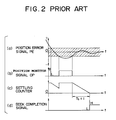
- FIG.2 is a waveform diagram showing the conventional settling monitor process.
- the seek operation has just been completed and the following control process starts.
- the position error signal PE shows a large position error and is outside of a settling range indicated by hatching.
- the settling range is selected so that it is narrower than the detection range of the window comparator 116.
- FIG.2(b) shows a position monitor signal OP generated when the level of the position error signal PE is outside of the settling range.
- the servo MPU 108 has a built-in timer counter formed with hardware or firmware for use in supervision of settling (hereinafter this timer counter is referred to as a settling counter).
- the settling counter is continuously preset to a predetermined value which defines a predetermined settling monitor time Tst1.
- the settling counter value becomes equal to zero, the seek completion signal is generated, as shown in FIG.2(d). In this manner, it is determined that the settling (seek) operation has been completed when it is detected that the position error signal PE is continuously within the settling range during the predetermined settling monitor time Tst1.
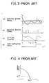
- the settling monitor time Tst1 can be lengthened. However, this means increases in the access time, because the seek completion signal is generated at a delayed time.
- FIG.4 is a graph having a horizontal axis showing the settling monitor time Tst1, and a vertical axis showing the error rate (log scale) indicating how frequently following control errors occur.
- the settling monitor time Tst1 is determined based on an error rate of, for example 10 ⁇ 12.
- the settling monitor time Tst1 be short in order to shorten the access time.
- an allowable error rate must be satisfied.
- a mechanical part which is an object to be controlled has a plurality of resonant structures, which are excited due to a large acceleration during the seek operation.
- the cases as shown in FIG.4 frequently take place under a condition where attenuating vibrations having different frequencies remain and are superimposed.
- An object of the present invention is to provide a settling monitor system of a following control apparatus capable of reducing the error rate without increasing the settling monitor time.
- a system for monitoring settling of a transient response of a load controlled by a following controller comprising: state estimation means for generating a state estimation quantity which shows an estimated state of the load; settling evaluation function operation means, coupled to the load and the state estimation means, for generating an evaluated output by inputting, to a predetermined settling evaluation function, the state estimation quantity and a control quantity output to the load by the following controller; timer means for generating time data showing a time passage of supervision of settling; comparator means, coupled to the settling evaluation function operation means and the timer means, for comparing the evaluated output and the time data with each other and for replacing the time data of the timer means with the evaluated output on the basis of a comparison result; and decision making means, coupled to the timer means, for generating a settling completion signal when the time data shows a predetermined time.
- FIG.5 shows a settling monitor system for a following control apparatus.
- the settling monitor system shown in FIG.5 supervises the settling of a transient response to a controlled load 2 driven by a following control unit 1.
- a settling evaluation function operation unit 4 receives at least an output quantity y of the controlled load 2 and a state estimation quantity X (estimated quantity) calculated by the state estimation unit 3, and obtains an evaluated output m by inserting these quantities into a settling evaluation function.
- a count unit 5 measures a predetermined settling monitor time.
- a comparator unit 6 compares the evaluated output m with a counted value Ctr of the count unit 5, and replaces the settling monitor time of the count unit 5 with the evaluated output m.
- a settling completion decision unit 7 generates a settling completion signal when the count value of the count unit 5 has become equal to the predetermined settling monitor time measured by the count unit 5. It should be noted that the completion of settling is detected not only through the output quantity y of the controlled load 2, but also through the state estimation quantity X obtained by the state estimation unit 3.
- the following control unit 1 is, for example, a servo controller that positions a head (which is the controlled load 2) on a rotary recording medium.
- the state estimation unit 3 generates estimated data showing a movement velocity v of the head.
- the settling evaluation function operation unit 4 calculates, on the basis of the head position y and the movement velocity v, a settling monitor time m necessary to supervise settling.
- the state estimation quantity X and the movement velocity v are estimated values and thus, hereinafter, "hat" symbols are attached thereto in equations and drawings, such as X ⁇ and v ⁇ , for example.
- An initial value No of the predetermined settling monitor time is preset in the count unit 5.
- the initial value No may be replaced by the calculation result m output by the settling evaluation function operation unit 4, as will be described in more detail later.
- the count unit 5 outputs the count value Ctr obtained by counting down from the preset initial value No, or the calculation result m preset by the comparator unit 6.
- the comparator unit 6 compares the preset count value Ctr with the calculation result m output by the settling evaluation function operation unit 4. If the count value Ctr is larger than the estimated output m, that is: Ctr > m then the count unit 5 is made to count down continuously without substituting the calculation result m for the count value of the count unit 5. Further, the comparator unit 6 compares the count value Ctr with the evaluation output m. If the count value Ctr is smaller than or equal to the calculation result m, that is: Ctr ⁇ m then the evaluated output m is preset in the count unit 5, and it is made to continuously execute down-counting. The settling completion decision unit 7 generates the settling completion signal when the count value Ctr becomes equal to zero.
- the state estimation unit 3 estimates not only the output quantity y of the controlled load 2 but also other states X.
- the disk apparatus not only the estimated head position y but also the estimated velocity v are contained in the vector X.
- a following control error which occurs after the completion of settling by using the head position y and the estimated velocity v in order to supervise the settling. That is, immediately before a following control error occurs, both the velocity component v and the position signal y increase. This case is estimated so that the controlled load 2 is moving toward the outside of the settling range.
- an updated settling monitor time (m) slightly longer than the initially set time (No) is needed.
- FIG.6A is a perspective view of the magnetic disk apparatus according to the embodiment of the present invention
- FIG.6B is a cross sectional view of the apparatus shown in FIG.6A
- the magnetic disk apparatus is composed of disks 201, magnetic heads 202, an actuator 203, a voice coil motor (VCM) 204, a housing 205, load springs 206, a frame 207, head arms 208, and a spindle motor 209.
- the voice coil motor 204 includes magnets 204a, a coil 204b and yorks 204c.
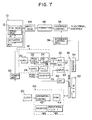
- FIG.7 is a block diagram of an electrical system of the magnetic disk apparatus shown in FIGS.6A and 6B.
- a disk mechanism 10 accommodates the magnetic disks 201 (FIGS.6A and 6B) which are rotated at a constant velocity by the spindle motor 209.
- the heads 202 include two different types, namely, read/write (R/W) heads 12, and servo heads 14.
- the disks 201 include magnetic disks for use in information recording and a magnetic disk (servo disk) for use in servo control.
- Each of the read/write heads 12 and the servo heads 14 includes a built-in head IC. For the sake of simplicity, a pair of the read/write head 12 and the servo head 14 is illustrated in FIG.7.
- the heads 12 and 14 are driven by the actuator 203 so that they move in the radial directions of the disks 201 and are positioned on desired tracks.
- a servo signal recorded on the servo disk is read by the servo head 14, and then applied to a servo demodulation circuit 18.
- the servo demodulation circuit 18 is composed of an AGC (Automatic Gain Control) circuit 20, a peak hold circuit 22, a difference/sum creation circuit 24, a synchronous detection circuit 26, and a PLL (Phase Locked Loop) circuit 28.
- the AGC circuit 20 amplifies the servo signal, and the peak hold circuit 22 detects a peak value of the amplified servo signal, which is output to difference/sum creation circuit 24.
- This circuit 24 generates position signals POSN and POSQ.
- FIG.8 shows waveforms of the servo signal obtained when the servo head 14 moves from a cylinder CY0 to a cylinder CY2.
- the waveforms of the servo signal shown in FIG.8 are illustrated with respect to the respective cylinder positions.
- the servo signal is output to the peak hold circuit 22, which holds four peak parts existing between two consecutive large amplitudes and calculates the difference between the held peaks as well as the sum thereof. In this manner, the position signals POSN and POse are generated.
- a difference signal (N-Q) and a sum signal (N+Q) are generated from the position signals POSN and POSQ.
- a tracking cross pulse TXPL can be generated from the difference and sum signals.
- a tracking cross counter 75 counts the number of tracking cross pulses TXPL, and obtains the number of tracks through which the head has passed up to the target track position. Even in the following control process of positioning the head on the target track after the completion of the seek operation, the position signal POSN is used and controlled so that the position signal POSN always indicates zero.
- the synchronous detection circuit 26 in the servo demodulation circuit 18 detects synchronous components of the servo signal shown in FIG.8, and controls the PLL circuit 28 on the basis of the synchronous components.
- the peak hold circuit 22 creates timings for detecting the peaks of the servo signal except for the synchronous components.
- the servo demodulation circuit 18 is, for example, SS132H567 manufactured by silicon system (SSI).
- the signals POSN and POSQ generated by the servo demodulation circuit 18 are converted by AD converters (ADC) 30 and 32, respectively, and output to a DSP (Digital Signal Processing) bus 36.
- ADC Analog Signal Processing
- the number of tracks counted by the track counter 75 is output to the DSP bus 36 via an input circuit 34.
- a servo control DSP 40 includes an operation/control circuit 42, an internal data RAM 44, an internal register 46, and a peripheral I/O device 48, such as a timer.
- the servo control DSP 40 receives servo demodulation information from the servo demodulation circuit 18 via the DSP bus 36, and executes a servo control by using a servo control program stored in a program storage ROM 52.
- a clock generator 50 is connected to the servo control DSP 40.
- the servo control DSP 40 can communicate with an upper (high-order) computer via the DSP bus 36, a register 54 for use in communication, an interface MPU 56, and an interface control circuit 58.
- the servo control DSP 40 receives an access instruction from the upper computer, and executes the seek operation and the following control process after the completion of the seek operation.
- the servo control DSP 40 makes a decision about the settling condition by using a state quantity obtained by a state-space method and a control quantity of the actuator 16.
- the servo control DSP 40 is formed with, for example, TMS320C25 manufactured by Texas Instruments.
- the control quantity calculated by the servo control DSP 40 passes through the DSP bus 36, and is converted into an analog signal by a DA converter 60.
- This analog signal is amplified by a power amplifier 62, and an amplified analog signal drives the voice coil motor 204 of the actuator 203.
- a write/read circuit 64 and a formatter circuit 66 are provided for the read/write head 12. During a write access, write data supplied from the upper computer is written into the related disk by the read/write head 12. During a read access, data is read out from the disk by the read/write head 12 and is transferred to the upper computer.
- FIG.10 shows a basic structure of the settling monitor system of the present invention which is realized by the servo control DSP 40.
- the settling monitor system is composed of a sum point 68, an observer controller 70 having a state estimation function by a state-space method, a controlled load 72, and a settling evaluation function calculator 74.
- the controlled load 72 includes the actuator 203 and the heads 202.
- a reference value r and the output quantity y of the controlled load 72 are input to the observer controller 70, which outputs a driving quantity u to the controlled load 72 so that the reference value r and the output quantity y are equal to each other.
- the output quantity y can be generated by the track cross counter 75 which receives the signals POSN and POSQ.
- the observer controller 70 has a state estimation function of simulating, on the basis of the output quantity y of the controlled load 72 (that is, the head position y) and the driving quantity u, the state of the controlled load 72 by the state-space method. By this state estimating function, the observer controller 70 generates a state estimation quantity X.
- the state estimation quantity X includes, for example, a velocity component of the head.
- the settling evaluation function calculator 74 operates an estimation evaluation function by using not only the head position y but also the state estimation quantity X, and obtains a time necessary to supervise the settling.
- the optimal values of constants L1, L2, K1 and K2 can be obtained by solving a Riccati's equation by a known LQR method (see Gene F. Franklin et al., "Digital Control of Dynamic Systems [Second Edition], 1990, pp.238 - pp.273 and pp.417 - pp.431, 1990, the disclosure of which is hereby incorporated by reference).
- M(y n ) m o [(Yn - Y1) posit(
- This settling evaluation function does not define a step change as shown in FIG.11, but instead defines a gradual change as shown in FIG.12.
- the settling evaluation function shown in FIG.12 is particularly effective to a condition that has a large amount of random noise.
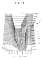
- M(y n , V ⁇ n) m o ⁇ posit(
- M(y n , V ⁇ n) is not larger than m o . That is, if the calculation result of M(y n , V ⁇ n) is larger than m o , M(y n , V ⁇ n) is set equal to m o .
- This settling evaluation function supervises the settling by referring to not only the position error y n , but also to the estimated velocity V ⁇ n.
- the magnitude of the settling evaluation function M is as shown in FIG.12, which is a contour diagram.
- the settling evaluation function shown in FIG.13 is effective to a condition in which there are small noise components and large residual vibration components. Hence, this settling evaluation function will be most suitable for the settling supervision for the following control of the head positions.
- FIGS.14A and 14B are flowcharts of the settling monitor process executed by the servo control DSP 40 shown in FIG.7.
- the process shown in FIG.14A starts when the seek operation of the head 12 has been completed and the control process switches to the following control process for following up positioning of the head 12 on a target track.
- the initial value No of the settling counter Ctr is equal to the settling monitor time Tst1, which corresponds to an error rate of 10 ⁇ 12, for example as shown in FIG.4.
- Tst1 the settling monitor time
- the head driving quantity u n and the output quantity x n obtained at the present sampling time are generated at step S3.
- the calculation based on the aforementioned state-space method is executed, so that the next driving quantity u n+1 is obtained.
- the position error y n+1 and the estimated velocity V n+1 are obtained.
- step S5 the time n necessary for monitoring the settling is calculated by the setting evaluation function N, as shown in FIG.12 or FIG.13, into which the position error y n+1 and the estimated velocity V n+1 are inserted.
- step S6 it is determined whether or not the count value of the setting counter Ctr is equal to or smaller than zero. When the counter value Ctr is equal to zero, it is determined that the head 12 is already in the settled state. In this case, the settling is not monitored, and steps S2 - S5 are repeatedly carried out.
- step S6 When it is determined, at step S6, that the counter value Ctr is larger than zero, it is determined that the settling is being monitored.
- step S7 it is determined whether or not the counter value of the settling counter Ctr is larger than the time m (obtained at step S5) necessary for monitoring the settling.
- step S8 is skipped, and the counter value of the settling counter Ctr is decremented at step S9.
- step S8 the counter value of the settling counter Ctr is preset to the time m necessary for monitoring the settling.
- step S10 it is determined whether or not the counter value of the settling counter Ctr is larger than or equal to zero.
- step S2 is executed.
- the servo control DSP 40 informs the upper computer of the completion of settling at step S11. After this, the write operation can be started.
- the counter value of the settling counter Ctr is decremented without replacing the present settling counter value with the time m necessary for monitoring the settling if it is determined, at step S7, that the present setting counter value Ctr is larger than the time m obtained at step S5.
- the velocity component is used as the estimated state quantity.
- other estimated state quantities such as acceleration components.
- the present invention is not limited to the magnetic disk apparatus as has been described above, but may be applied to other apparatuses, such as an optical disk apparatus and a magneto-optic disk apparatus. Further, the present invention is not limited to these disk devices, but may be applied to the settling monitor for other following control apparatuses.
Landscapes
- Engineering & Computer Science (AREA)
- Human Computer Interaction (AREA)
- Manufacturing & Machinery (AREA)
- Physics & Mathematics (AREA)
- General Physics & Mathematics (AREA)
- Automation & Control Theory (AREA)
- Moving Of The Head To Find And Align With The Track (AREA)
- Moving Of Head For Track Selection And Changing (AREA)
Applications Claiming Priority (2)
| Application Number | Priority Date | Filing Date | Title |
|---|---|---|---|
| JP3014624A JP2611049B2 (ja) | 1991-02-06 | 1991-02-06 | 追従制御装置の整定監視方式 |
| JP14624/91 | 1991-02-06 |
Publications (3)
| Publication Number | Publication Date |
|---|---|
| EP0498643A2 true EP0498643A2 (de) | 1992-08-12 |
| EP0498643A3 EP0498643A3 (en) | 1992-11-25 |
| EP0498643B1 EP0498643B1 (de) | 1996-12-04 |
Family
ID=11866361
Family Applications (1)
| Application Number | Title | Priority Date | Filing Date |
|---|---|---|---|
| EP92300984A Expired - Lifetime EP0498643B1 (de) | 1991-02-06 | 1992-02-05 | Stabilisierungsanordnung für ein Spurnachlaufservosystem |
Country Status (4)
| Country | Link |
|---|---|
| US (1) | US5307330A (de) |
| EP (1) | EP0498643B1 (de) |
| JP (1) | JP2611049B2 (de) |
| DE (1) | DE69215550T2 (de) |
Cited By (1)
| Publication number | Priority date | Publication date | Assignee | Title |
|---|---|---|---|---|
| EP1840881A3 (de) * | 2006-03-30 | 2007-12-26 | Fujitsu Ltd. | Niederlassungsbeurteilungsverfahren für ein Positionierungssteuerungsgerät, Positionierungssteuerungsgerät und Plattengerät |
Families Citing this family (12)
| Publication number | Priority date | Publication date | Assignee | Title |
|---|---|---|---|---|
| JP2621125B2 (ja) * | 1992-03-31 | 1997-06-18 | 富士通株式会社 | オントラック判定方法 |
| JP3829994B2 (ja) * | 1995-01-06 | 2006-10-04 | 富士通株式会社 | ファイル装置の開発装置及び開発システム |
| JP3875294B2 (ja) * | 1995-11-17 | 2007-01-31 | 富士通株式会社 | ディスク装置 |
| US5832003A (en) * | 1996-04-25 | 1998-11-03 | Tektronix, Inc. | Video error/distortion checker |
| US6166876A (en) * | 1998-02-24 | 2000-12-26 | Seagate Technology, Inc. | Minimizing settling time in a disc drive servo system |
| JP2001126424A (ja) * | 1999-10-27 | 2001-05-11 | Hitachi Ltd | 記録再生装置 |
| WO2001043122A2 (en) | 1999-12-10 | 2001-06-14 | Seagate Technology Llc | Magnetic disc having physical servo patterns with a magnetic carrier, and method of making and using the same |
| US6924961B1 (en) * | 2002-08-30 | 2005-08-02 | Western Digital Technologies, Inc. | Method and apparatus for self servowriting of tracks of a disk drive using an observer based on an equivalent one-dimensional state model |
| US6906886B2 (en) * | 2003-09-08 | 2005-06-14 | Seagate Technology Llc | Peak to peak detect method to protect seek/settle induced encroachment |
| US6999263B1 (en) * | 2003-10-24 | 2006-02-14 | Western Digital Technologies, Inc. | Method and apparatus for self servowriting of tracks of a disk drive using a servo control loop having a two-dimensional weighted digital state compensator |
| JP4690948B2 (ja) | 2006-03-31 | 2011-06-01 | 東芝ストレージデバイス株式会社 | 位置決め制御装置の整定判定方法及び位置決め制御装置 |
| JP4991201B2 (ja) | 2006-07-28 | 2012-08-01 | 株式会社東芝 | 位置決め制御装置の整定判定方法及び位置決め制御装置 |
Family Cites Families (13)
| Publication number | Priority date | Publication date | Assignee | Title |
|---|---|---|---|---|
| US3881184A (en) * | 1974-05-28 | 1975-04-29 | Ibm | Adaptive digital servo system |
| US4134053A (en) * | 1976-10-26 | 1979-01-09 | Xerox Corporation | Method and means for capturing magnetic tracks |
| US4381526A (en) * | 1980-11-10 | 1983-04-26 | Memorex Corporation | Velocity control system for a data storage apparatus |
| US5095471A (en) * | 1982-05-10 | 1992-03-10 | Digital Equipment Corporation | Velocity estimator in a disk drive positioning system |
| US4679103A (en) * | 1986-04-29 | 1987-07-07 | International Business Machines Corporation | Digital servo control system for a data recording disk file |
| US4697127A (en) * | 1986-06-09 | 1987-09-29 | International Business Machines Corporation | Adaptive control technique for a dynamic system |
| JPS63275082A (ja) * | 1987-05-06 | 1988-11-11 | Sony Corp | ディスクドライブのヘッド位置決め制御系 |
| JPS63298861A (ja) * | 1987-05-29 | 1988-12-06 | Toshiba Corp | ディスク装置 |
| JPH0632202B2 (ja) * | 1988-05-13 | 1994-04-27 | 富士通株式会社 | ディスク装置の防振構造 |
| US4823868A (en) * | 1988-05-26 | 1989-04-25 | Deere & Company | Intercooler and method of assembling the same |
| JPH0235269A (ja) * | 1988-07-21 | 1990-02-05 | Yamaha Motor Co Ltd | 油圧トランスミッションのシフト装置 |
| US5182685A (en) * | 1989-02-03 | 1993-01-26 | Seagate Technology, Inc. | Stepper motor torque variance compensation using varied applied voltage |
| JPH0831263B2 (ja) * | 1989-04-04 | 1996-03-27 | 株式会社東芝 | 磁気記録再生装置の磁気ヘッド駆動制御装置 |
-
1991
- 1991-02-06 JP JP3014624A patent/JP2611049B2/ja not_active Expired - Fee Related
-
1992
- 1992-02-05 DE DE69215550T patent/DE69215550T2/de not_active Expired - Fee Related
- 1992-02-05 US US07/831,530 patent/US5307330A/en not_active Expired - Fee Related
- 1992-02-05 EP EP92300984A patent/EP0498643B1/de not_active Expired - Lifetime
Cited By (1)
| Publication number | Priority date | Publication date | Assignee | Title |
|---|---|---|---|---|
| EP1840881A3 (de) * | 2006-03-30 | 2007-12-26 | Fujitsu Ltd. | Niederlassungsbeurteilungsverfahren für ein Positionierungssteuerungsgerät, Positionierungssteuerungsgerät und Plattengerät |
Also Published As
| Publication number | Publication date |
|---|---|
| US5307330A (en) | 1994-04-26 |
| DE69215550T2 (de) | 1997-03-27 |
| EP0498643A3 (en) | 1992-11-25 |
| JPH04298868A (ja) | 1992-10-22 |
| EP0498643B1 (de) | 1996-12-04 |
| JP2611049B2 (ja) | 1997-05-21 |
| DE69215550D1 (de) | 1997-01-16 |
Similar Documents
| Publication | Publication Date | Title |
|---|---|---|
| EP0498643B1 (de) | Stabilisierungsanordnung für ein Spurnachlaufservosystem | |
| KR930009998B1 (ko) | 변환기의 위치 결정 제어방식 | |
| KR0128040B1 (ko) | 디스크 기록 매체를 이용하는 데이타 저장장치의 디지탈 서보제어장치 및 방법 | |
| US5262907A (en) | Hard disc drive with improved servo system | |
| US5510939A (en) | Disk drive with adaptive positioning | |
| US5164931A (en) | Method and apparatus for control of positioning | |
| JP2671780B2 (ja) | 記録再生分離型磁気ディスク装置用サーボ装置並びにディスク装置におけるアクチュエータ力定数推定方法及び補償方法 | |
| KR100305953B1 (ko) | 트랙형태오차의전달을감소시키는방법과서보기록장치 | |
| US6754019B2 (en) | System and method for implementing a rotary memory device | |
| EP0550302B1 (de) | Zielspurpositionswiedergabesystem für optische Platte | |
| US6504670B1 (en) | Method and apparatus for reducing oscillations excited during a seek operation in a disk drive | |
| EP0516854B1 (de) | Gerät zur kopfpositionssteuerung in einem plattenspeichergerät und verfahren zu dessen steuerung | |
| US6153997A (en) | Disk apparatus and method of controlling disk apparatus | |
| US7006321B2 (en) | Data storage apparatus, rotation control apparatus, and rotation control method | |
| US20090109567A1 (en) | Seek control apparatus and method for generating control data for seek control | |
| US20020003677A1 (en) | Feedback control system, control method, magnetic disk unit and method of controlling magnetic disk unit | |
| US20030103286A1 (en) | Soft sensor for operating shock in a disc drive | |
| US4270073A (en) | Position control in disk drive system | |
| JP2647291B2 (ja) | 記録装置のヘッドを高速に位置決めする方法 | |
| US5661617A (en) | Head positioning control system | |
| EP0147918B1 (de) | Zugriffsschaltung für eine Magnetpatte | |
| US6169641B1 (en) | Methods and devices for controlling a head position actuator of a disk drive | |
| EP0244980B1 (de) | Methode und Generator zur Signalerzeugung in Abhängigkeit der Änderung einer Grösse unter Verwendung der Abtast-Haltetechnik | |
| KR100246791B1 (ko) | 하드디스크구동장치의스핀들모터제어장치와방법 | |
| JPH04112205A (ja) | 位置決め制御装置 |
Legal Events
| Date | Code | Title | Description |
|---|---|---|---|
| PUAI | Public reference made under article 153(3) epc to a published international application that has entered the european phase |
Free format text: ORIGINAL CODE: 0009012 |
|
| AK | Designated contracting states |
Kind code of ref document: A2 Designated state(s): DE FR GB |
|
| PUAL | Search report despatched |
Free format text: ORIGINAL CODE: 0009013 |
|
| AK | Designated contracting states |
Kind code of ref document: A3 Designated state(s): DE FR GB |
|
| 17P | Request for examination filed |
Effective date: 19930518 |
|
| 17Q | First examination report despatched |
Effective date: 19950608 |
|
| GRAG | Despatch of communication of intention to grant |
Free format text: ORIGINAL CODE: EPIDOS AGRA |
|
| GRAH | Despatch of communication of intention to grant a patent |
Free format text: ORIGINAL CODE: EPIDOS IGRA |
|
| RBV | Designated contracting states (corrected) |
Designated state(s): DE |
|
| GRAH | Despatch of communication of intention to grant a patent |
Free format text: ORIGINAL CODE: EPIDOS IGRA |
|
| GRAA | (expected) grant |
Free format text: ORIGINAL CODE: 0009210 |
|
| AK | Designated contracting states |
Kind code of ref document: B1 Designated state(s): DE |
|
| REF | Corresponds to: |
Ref document number: 69215550 Country of ref document: DE Date of ref document: 19970116 |
|
| PLBE | No opposition filed within time limit |
Free format text: ORIGINAL CODE: 0009261 |
|
| 26N | No opposition filed | ||
| PGFP | Annual fee paid to national office [announced via postgrant information from national office to epo] |
Ref country code: DE Payment date: 20030213 Year of fee payment: 12 |
|
| PG25 | Lapsed in a contracting state [announced via postgrant information from national office to epo] |
Ref country code: DE Free format text: LAPSE BECAUSE OF NON-PAYMENT OF DUE FEES Effective date: 20040901 |