EP0498676B1 - Verfahren und Vorrichtung zur Grundwasser-Extraktion mit Hochvacuum - Google Patents
Verfahren und Vorrichtung zur Grundwasser-Extraktion mit Hochvacuum Download PDFInfo
- Publication number
- EP0498676B1 EP0498676B1 EP92301069A EP92301069A EP0498676B1 EP 0498676 B1 EP0498676 B1 EP 0498676B1 EP 92301069 A EP92301069 A EP 92301069A EP 92301069 A EP92301069 A EP 92301069A EP 0498676 B1 EP0498676 B1 EP 0498676B1
- Authority
- EP
- European Patent Office
- Prior art keywords
- liquid
- pipe
- vacuum
- water table
- gas
- Prior art date
- Legal status (The legal status is an assumption and is not a legal conclusion. Google has not performed a legal analysis and makes no representation as to the accuracy of the status listed.)
- Expired - Lifetime
Links
Images


Classifications
-
- B—PERFORMING OPERATIONS; TRANSPORTING
- B09—DISPOSAL OF SOLID WASTE; RECLAMATION OF CONTAMINATED SOIL
- B09C—RECLAMATION OF CONTAMINATED SOIL
- B09C1/00—Reclamation of contaminated soil
- B09C1/005—Extraction of vapours or gases using vacuum or venting
Definitions
- This invention is directed to a process and apparatus for removing chemical contaminants from groundwater.
- Contaminants can exist in subsurface soil and groundwater in the liquid or vapour phase as discrete substances and mixed with and/or dissolved in groundwater and soil gases.
- Various contaminants can be found in groundwater and soil, such as volatile compounds, including volatile organic compounds, nonvolatile materials, metal contaminants, and the like.
- Such contaminants can be found and dealt with in the vadose (unsaturated) zone found between the surface of the earth and the water table, at the interface between the vadose zone and the water table, and in the saturated zone below the water table.
- soil and groundwater are contaminated with suspended or water-soluble chemicals, or both.
- a variety of techniques have been used for removal of contaminants and remediation of affected soil.
- One common technique entails the excavation and off-site treatment of the soil.
- Another technique entails saturating the contaminated soil with water in situ, causing the contaminants to be leached slowly from the soil by the water. The contaminated water can then be removed.
- the system comprises a conduit extending from the ground surface to a point just above the water table, a collection head fitted on the lower end of the conduit, a collection vessel connected to the upper end of the conduit, and an exhaust means for creating less than atmospheric pressure in the vessel.
- the collection head has a liquid impermeable end portion and a liquid permeable intermediate portion for permitting the passage of liquid.
- the process comprises providing an opening in the ground to a point beneath the surface of the water table, positioning the conduit with the collection head in place so that the liquid permeable wall of the collection head is just above the surface of the water table, connecting the conduit to the collection vessel intake, and exhausting air and other gaseous materials from the vessel to cause liquid to flow into the collection head through the conduit into the vessel.
- the process entails drilling one or more wells into the subsurface media in the contaminated area, the well being constructed so that fluids in the vadose zone can flow into the well, whereas the liquid in the saturated zone below the water table cannot substantially flow into the well.
- the borehole and conduit of the well can optionally extend below the water table, in which case the vacuum applied to the upper portion of the conduit will be effective to draw contaminant from the vadose zone, but insufficient to draw a significant amount of water from the saturated zone into the conduit. If it is desired to remove groundwater from below the water table, this removal is accomplished either by a separate sampling device situated in the borehole or through a separate well.
- Stinson "EPA Site Demonstration of the Terra Vac In Situ Vacuum Extraction Process in Groveland, Massachusetts", Air & Waste Management Association, Vol. 39, No. 8, pages 1054 to 1062 (1989), discloses an evaluation of an in situ vacuum extraction process.
- the process entails removal of contaminants from the vadose zone by vacuum.
- Wells are installed in the contaminated vadose soil.
- a vacuum pump or blower induces air flow through the soil, stripping and volatilising volatile organic compounds from the soil matrix into the air stream.
- Liquid water if present in the soil, is also extracted along with the contamination.
- the two-phase stream of contaminated air and water flows to a vapour/liquid separator where contaminated water is removed.
- U.S. Patent 4,593,760 disclose processes for removal of volatile contaminants from the vadose zone of contaminated ground by pumping volatilised contaminants from the vadose zone using one or more vacuum extraction wells.
- Venting for the Removal of Hydrocarbon Vapours from Gasoline Contaminated Soil J. Thornton and W. Wootan, J. Environ. Sci. Health , A17(1), 31-44 (1982) discloses the results of an experiment investigating the use of a venting strategy to remove gasoline vapours from contaminated soil strata.
- a contained gasoline leak was created in a large outdoor facility which simulates soil strata and a static water table. An air flow was established, and vapour samples taken before, during, and after venting were checked for hydrocarbon content.
- U.S. Patent 4,892,664 discloses a method and system for decontaminating water, such as groundwater or process effluent, which is contaminated by small concentrations of dissolved volatile organic compounds.
- the process includes introducing a flow of the water to an air stripping stage in which the water is directed through the column to air strip organic molecules from the contaminated water, releasing the decontaminated water to the environment, pretreating the organic compounds carrying air in the substantial absence of water through a preheater, passing the heated air through a catalytic stage that oxidises the organic compounds, and releasing the gaseous effluent from the catalytic stage to the atmosphere.
- Water containing small concentrations of dissolved volatile organic compounds can also be decontaminated by including an apparatus for retrofitting an existing air stripper for this purpose.
- U.S. Patent 3,743,355 discloses a method for withdrawing hazardous gases from a water saturated subterranean formation containing a minable mineral deposit. Wells are drilled through the subterranean formation to establish permeability to gas within the subterranean formation. Gas is then withdrawn from the formation by means of the wells.
- U.S. Patent 4,444,260 (Boyd et al.) discloses a method for the treatment of oil well production streams to process oil-contaminated sand to recover oil therefrom and produce an ecologically acceptable clean sand residue.
- the process entails separating the production fluid from an oil well having sand entrained therein from a plurality of components, one of which comprises an oil-contaminated sand.
- the contaminated sand is contacted with a light oil solvent to initiate a solvating action of the oil contaminant.
- the resulting mixture of oil-contaminated sand and solvent is then contacted with water and the system then gravity separated into discrete sand, water, and oil phases.
- the oil and water phases can be removed from the sand and the sand phase again contacted with water and the resulting mixture is then subjected to gravity separation to produce separate sand and water phases.
- the water phase is then removed and the sand passed to a suitable disposal facility.
- U.S. Patent 4,730,672 (Payne) and U.S. Patent 4,890,673 (Payne), disclose a method and apparatus for collecting volatile contaminants from the vadose layer of earth.
- the apparatus is a closed-loop device which includes one or more contaminant withdrawal wells surrounded by multiple air reinjection wells connected by a conduit.
- One or more pumps serve to draw volatilised contaminant through the withdrawal well to the connecting conduit where it is captured or neutralised. Residual air from the withdrawal well is urged back into the ground through the air reinjection wells to encourage further contaminant to move toward the withdrawal well for collection.
- U.S. Patent 4,945,988 discloses a process for removing and disposing of or neutralising volatile contaminants existing in the vadose zone of earth and also in a below ground aquifer.
- the process includes the injection of substantially oxygen free air into the aquifer to retard the formation of aerobic bacteria and injection of oxygen rich air into the vadose zone to stimulate bacterial growth which aids contaminant recovery. Volatilised contaminants are pulled out of the soil through withdrawal wells which terminate in the vadose zone.
- U.S. Patent 4,886,119 discloses a process for driving volatile impurities from a ground by means of air by aspirating an afterflow air and impurities containing gases which penetrated through a permeable wall of a shaft in a ground, at one or several locations.
- air afterflow passages are extended to these regions for supplying the afterflow air, and an adjustable afterflow resistance is arranged in the passages for influencing a negative pressure value and a flow speed in these regions.
- U.S. Patent 3,743,355 discloses a method for withdrawing hazardous gases from a water saturated subterranean formation containing a mineral deposit suitable for mining. The process entails drilling wells through the subterranean formation and withdrawing water from the subterranean formation to establish permeability to gas within the subterranean formation. Gas is then withdrawn from the formation by means of the wells. The method is particularly applicable for reducing the influx of radon into a mine contained in a mineral deposit.
- EP-A-0 420 656 discloses a process for extracting contaminants from soil both above and below the water table.
- the process comprises placing a perforated riser pipe in a borehole in a selected portion of the contaminated area, wherein the perforations of the riser pipe are situated below the water table.
- some of the perforations in the riser pipe can also be situated in the vadose zone above the water table.
- a vacuum is then applied to the pipe to draw gases and liquids from the soil into the pipe and to transport the gases and liquids to the surface as a common stream.
- the common stream is separated into a primarily liquid stream and a primarily gaseous stream, and the separated streams are then treated separately.
- DE-A-3,739,126 discloses a method for decontaminating an area of ground in situ which had been contaminated by oil or hydrocarbon-containing materials. At least one suction shaft is dug in the contaminated area of ground via which a liquid, such as ground water and/or a cleaning liquid and/or gas is introduced at a distance from the suction shaft. The ground water or cleaning liquid becomes loaded with the contaminating material and is suctioned off and subsequently cleaned in a known manner.
- a liquid such as ground water and/or a cleaning liquid and/or gas
- US-A- 4 982 788 discloses removal of volatile contaminants from the ground by circulating air between two substantially parallel wells and by removing the vapors of the organic compound from the circulated air using at least one of a condenser and a demister. To enhance efficiency, the air is recirculated in a closed loop. The heat output of the condensation process is used to heat the recirculated air. Pipes having openings along only a limited portion of their lengths are placed in the wells and the depth of the openings adjusted to treat one level at a time, thereby preventing shunting of air through more porous soil layers. Flow rates can be equalized by using circumferentially placed induction wells surrounding an extraction well (or reverse) and by controlling air flow through individual sections of a given level.
- the present invention provides a process for removing contaminants from a contaminated area of the ground, the ground having a surface, a water table, and a vadose zone above the water table, the process comprising the steps of: providing a borehole in the contaminated area of the ground through the surface thereof to a depth below the water table; placing a perforated riser pipe in the borehole to a depth below the water table; placing a vacuum extraction pipe having an open distal end inside of the riser pipe, the distal end of the vacuum extraction pipe being located in the vicinity of the water table, applying a high vacuum of 24 to 98 kPa (7 to 29 inches of mercury) from a vacuum-forming apparatus to the vacuum extraction pipe at a location opposite to the open distal end; introducing a gas from a gas inlet into the perforated riser pipe, while the high vacuum is being applied to the vacuum extraction pipe, to enable the drawing of gases and liquid from the contaminated area of the ground into the perforated riser pipe and from the perforated riser pipe into the vacuum extraction pipe
- the present invention also provides apparatus for removing contaminants from a contaminated area of the ground, the ground having a surface, a water table, and a vadose zone above the water table, the apparatus comprising: a perforated riser pipe extending downwardly from the ground surface in a borehole to a depth of below the water table; a vacuum extraction pipe situated inside of the perforated riser pipe and having an open end at one end thereof, the open end being located in the vicinity of the water table within the perforated riser pipe; means for applying a high vacuum of 24 to 98 kPa (7 to 29 inches of mercury) to the vacuum extraction pipe at a location opposite to the open end; means for introducing a gas into the perforated riser pipe, while the high vacuum is applied to the vacuum extraction pipe, to enable the drawing of gases and liquid from the contaminated areas of the ground into the perforated riser pipe and then into the vacuum extraction pipe through the open end thereof, whereby the gases and liquid are transported through the vacuum extraction pipe to the ground surface at a sufficiently high velocity so as to
- the present invention is directed to a process and apparatus for the removal of contaminants from groundwater and soil. Contaminants can be present in the vadose zone and/or below the water table.
- a process in accordance with the invention comprises the steps of providing a borehole in the contaminated area, placing in the borehole a perforated riser pipe in which is situated a vacuum extraction pipe with an opening situated near, at, or at any point below the initial water table within the perforated riser pipe, applying a vacuum to the riser pipe through the vacuum extraction pipe while introducing a gas into the riser pipe so as to draw soil gases and entrained liquid into the riser pipe and to transport both the gases and the liquid to the surface through the vacuum extraction pipe, separating the liquid and the gases, and separately subjecting the separated liquid and gases to appropriate treatment.
- Treated water can be returned to the soil or disposed of in conventional ways.
- the riser pipe is constructed with perforations (screening) extending both below the natural water table and upward into the unsaturated (vadose) zone.
- the riser pipe is constructed with perforations (screening) extending only below the water table.
- the unsaturated zone can be the natural vadose zone lying above the natural water table, or an expanded "artificial" vadose zone created when removal of the groundwater through the extraction well causes local lowering of the water table.
- a vapour-liquid disengaging vessel such as a cyclone separator, knock-out pot or other suitable component, and after separation the phases can individually be routed to systems for contaminant removal by further treatment steps.
- Suitable processes for contaminant removal include filtration, adsorption, air stripping, settling, flocculation, precipitation, scrubbing and the like.
- the riser pipe can be constructed so that the screening is at all times below the water table, even in the situation in which removal of water causes local depression of the water table.
- the fluid transported to the surface is predominantly in the liquid phase, although it may still be necessary to provide vapour-liquid separation and individual phase treatment at the surface to deal with phase transformation which may occur as a result of turbulence and pressure reduction at the suction side of the vacuum device.
- Figure 1 illustrates schematically a vacuum extraction and treatment system, designated generally by the reference numeral 10.
- Seen in Figure 1 is a source 12 of volatile contaminants, creating a plume 14 of adsorbed, dissolved, or suspended free phase and gaseous phase contaminants in the soil 16 of the vadose (unsaturated) zone.
- the contaminants making up the plume 14 tend to leach or percolate downwardly toward the natural water table 18.
- Groundwater is moving in the direction of the arrows 19.
- Components lighter than water and not dissolved are depicted by the reference numeral 20, and tend to float at the top of the water table.
- Dissolved contaminants tend to percolate downwardly in a plume 22 below the water table 18, and free-phase components 24 heavier than water tend to migrate downwardly to the aquitard 26.
- An extraction well designated generally by the reference numeral 28, and which will be described in greater detail shortly, is sunk in the area of the plume 14 and extends through the vadose zone and below the natural water table 18.
- a vacuum extraction system designated by the reference numeral 32, preferably designed to generate high vacuum conditions, typically from about 24 to about 98 kPa (17.8 to 73.7 cm) of mercury. Gases removed by the vacuum extraction system 32 can be vented to atmosphere at 34 if within acceptable environmental limits, or further processed, such as by being incinerated or passed to a condenser, granular activated carbon filter, or other such component 36.
- the component 36 serves to remove contaminants from the extracted gases.
- Water extracted by the process can be treated by passing it through conventional systems for metals removal, volatile organic compound removal, or other steps of purification.
- the treated and purified water if it is of sufficient purity at this stage, can be returned to a sewer or directly to the ground as indicated at 38.
- Contaminants can be stored in drums 40 for eventual destruction or further processing.
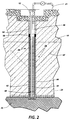
- FIG. 2 illustrates the extraction well 28 in greater detail.
- the extraction well 28 in the illustrated form includes an elongated borehole 42, into which is placed a perforated riser pipe 44 capped at the bottom.
- the riser pipe 44 is perforated either below the water table or both below and above the water table.
- the riser pipe includes an imperforate upper portion 46 and a perforate (screened) lower portion 48.
- the riser pipe 44 can be of any suitable material, such as polyvinyl chloride, metals, such as stainless steel, galvanised steel, or the like, plastics, including Teflon®, or the like.
- the screened or perforate portion can have perforations of any desired or suitable shape and size; for example, in one embodiment, the perforated portion can be equipped with 0.25 mm (0.010 inch) slots.
- the vacuum extraction pipe 30 can be of any suitable material, such as polyvinyl chloride, metals, such as stainless steel, galvanised steel, or the like, plastics, including Teflon®, or the like.
- the upper end of the riser pipe 44 is here shown to be associated with a concrete floor or deck, and is provided with a suitable pipe fitting 52, enabling the riser pipe 44 and the vacuum extraction pipe 30 to be coupled to the remainder of the vacuum extraction system 32 (not seen in Figure 2), with vacuum extraction pipe 30 being in fluid communication with the vacuum extraction system.
- Vacuum extraction pipe 30 can have an opening within the riser pipe 44 either below the water table, at the water table level, or slightly above but near to the water table.
- an air inlet 31 preferably equipped with an air flow gauge (not shown), which permits the introduction of air at any desired pressure, including reduced pressures, atmospheric pressure, or increased or forced pressures, into riser pipe 44.
- air pressure can be provided by an additional pump (not shown), by connecting the outlet or exhaust of the vacuum pump connected to vacuum extraction pipe 30 to air inlet 31, or the like.
- the air flow rate through air inlet 31 can range from nearly zero to any value less than the cubic meters per minute (CMM) rated capacity of the vacuum pump connected to vacuum extraction pipe 30.
- CMM cubic meters per minute
- the air introduced through air inlet 31 can, if desired, be heated to improve the extraction of some contaminants.
- air inlet 31 can be used as an inlet for introducing other materials or chemicals into the riser pipe and extraction stream, since chemicals or materials so introduced will pass down with the inlet air through the riser pipe to the bottom thereof, and then back up with the water and air mixture through vacuum extraction pipe 30, thus chemically or otherwise interacting with the water and air mixture.
- oxidisers or surfectants or other chemicals can be introduced for the treatment of water-borne or vapour-borne contaminants removed by the vacuum extraction pipe.
- Liquid drawn up through vacuum extraction pipe 30 generally is in one or more of the following forms: slugs, droplets, mist, and vapour.
- Air flow through the system is provided by one or more of the following: air from the unsaturated (vadose) zone; air from the dewatered saturated zone; and air from the air inlet mechanism 31, at reduced pressures, atmospheric pressure, or forced pressures. Thus, it is not required that air be extracted from the ground in the vicinity of the extraction well. Generally, a high vapour/air velocity is maintained through the system. Air velocity in the vacuum extraction pipe should be sufficient to carry or lift water in the vapour phase, either droplets of various sizes, or slugs, or the like, entrained in the air. Air velocity values in the range of 12.7 m/s (2,500 feet per minute) or greater generally suffice.
- the upper portion 46 of the riser pipe 44 is surrounded by a low permeability grout, such as bentonite cement 54, and below the grout 54 by a bentonite seal 56.
- a low permeability grout such as bentonite cement 54
- the area within the borehole 42 surrounding the slotted lower portion 48 of the riser pipe 44 and part of the upper portion 46 above the slotted lower portion 48 is packed with fine screened sand 49, to facilitate the flow of gas and liquid from the surrounding soil into the riser pipe 44.
- the extraction well 28 is constructed so that the screened lower portion 48 extends below the natural water table and upwardly into the vadose zone.
- the vadose zone into which the screened lower portion 48 extends can be the natural water table 18, or the expanded artificial vadose zone created when prolonged removal of groundwater through the extraction well causes local lowering of the water table, as indicated by the reference numeral 18′ in Figure 2.
- Placement of the screened lower portion 48 of the riser pipe 44 both below the water table and in the vadose zone allows soil gases (the vapour phase) to be drawn into the well under the influence of vacuum created by the extraction system 32 and to entrain the liquid phase so that both phases can be transported to the surface together.
- the two phases can be separated and differently treated.
- the extraction well 28 can be so constructed that the screening of the lower portion 48 is entirely submerged, i.e., disposed below the natural or actual water table, even after withdrawal of water under the influence of the vacuum extraction system 32.
- the fluid transported to the surface is predominantly in the liquid phase, although the influence of the vacuum generally results in the presence of a gas phase comprising volatilised liquids.
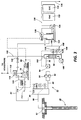
- FIG. 3 illustrates schematically in greater detail the vacuum extraction system 32 and the steps and apparatus for treating extracted material.
- a vacuum pump 78 driven by electric motor 80, is in fluid communication through a pipe 82, knock-out pot 84 and pipe 86 with the pipe fitting 52 of extraction well 28.
- the knock-out pot 84 can be of conventional design, familiar to those skilled in the art.
- the knock-out pot 84 serves to separate the two phases emerging from the extraction well 28, enabling them to be subjected to appropriate further processing.
- a pipe 88 is provided in association with the knock-out pot 84, to conduct effluent in the liquid phase through filtration and stripping steps.
- Filtration is provided in the illustrated embodiment by parallel filters 90 and 92 which can alternately or simultaneously be used in a conventional manner. Cut-off valves, omitted in the drawings for clarity, permit either filter 90 or 92 to be isolated and each filter to be removed, cleaned, or replaced. Suitable pressure gauges (not shown) can be placed on the suction and discharge sides of the filters 90 and 92 to indicate filter loading.
- Suitable filters 90 and 92 include SQ micron nylon filters, sold by Rosedale Products, Incorporated, capable of passing 14.0 l/s (222 gpm) at 103 X 10 4 pa (150 psi). Other separation techniques and apparatus can also be used.
- a pump 94 which, for erosion resistance, is preferably of the single stage progressive cavity (screw) type, serves to draw off the liquid phase effluent of the knock-out pot 84.
- An example of a suitable pump is sold by the Nemo Pump Division of Netzsch Incorporated, of Exton, PA, Model Ne-30A.
- other suitable apparatus can be used.
- the liquid phase is fed from the pump 94 through a pipe 96 to an optional air stripper assembly 98, the function of which is to remove from the effluent volatile organic compounds.
- a blower 100 associated with the air stripper assembly 98 delivers a flow of warm air through the housing of the air stripper assembly 98, carrying off the volatile organic compounds through the vent 102 to atmosphere or further processing (not shown).
- a transfer pump 104 discharging to a pipe 106, serves to transport liquid from the sump of the air stripper assembly 98 for further processing. The transfer pump 104 can be turned off in response to a low level switch 108 associated with the air stripper assembly 98.
- a high level switch 110 associated with the air stripper assembly 98 controls the pump 94 in response to high water level in the air stripper assembly 98.
- the air stripper assembly 98 can be a conventional "off-the-shelf" unit, familiar to those skilled in the art.
- the optional air stripper assembly 98 can, if desired, be omitted, and the effluent of the pipe 96 joined with the effluent of a pipe 120 from the processing of the gaseous phase from the extraction well. It is hypothesised that the intimate mixing of the air and water during extraction (at which time groundwater is extracted in an air stream under vacuum) allows the volatile compounds to come out of solution, thus obviating the need for later air stripping.
- Avoidance of the need for an air stripper assembly 98 also reduces the total volume of air streams bearing volatile organic compounds. In situations in which air emissions must be controlled, this is a distinct advantage.
- Another advantage of the two-phase vapour extraction process, as practised without additional air stripping, is that due to the low pressure at which the vapour/liquid mixing and separation are accomplished, there is no less oxygenation of the water than would result from conventional air stripping. It is to be expected that lower dissolved oxygen levels will result in less corrosion and fouling of downstream components of the apparatus.
- the vacuum pump 78 is of the liquid ring type, and is provided with a make up water line 112, served by a domestic supply.
- the make up water line 112 is provided with a solenoid actuated valve 114 responsive to the high water level switch 110 of air stripper assembly 98.
- the pump 78 exhausts to a vapour/liquid separator 116, the vapour effluent of which is conducted to atmosphere, or if appropriate to further processing through a pipe 118.
- the bulk of the liquid effluent from the vapour liquid separator 116 passes through the pipe 120 to a sump 122, where it joins the effluent of the pipe 106, the liquid output of the air stripper assembly 98.
- a fraction or all of the liquid effluent of the vapour liquid separator 116 can be drawn off through a line 124 to join the flow in the make up water line 112 servicing the liquid ring pump 78.
- a pump 126 controlled by a low level cut-off switch 128, draws liquid from the sump 122 and propels it through a pipe 130 for further processing.
- the liquid is passed in two stages through canisters 132 and 134 containing granular activated carbon. Other contaminant removal steps or techniques can be used.
- the treated water emerges through a pipe 136 and is of sufficient purity to allow its return to the soil or a sewer without further treatment.
- FIG 4 illustrates schematically an example of an optional air inlet well 57.
- the air inlet well 57 comprises a borehole 58, which receives a pipe 60.
- the pipe 60 in one operative embodiment comprises a 10.2 cm (four inch) diameter PVC pipe, capped at the bottom, and having a screen of 0.25 mm (0.010 inch) slots.
- the pipe 60 is surrounded at its upper end by a cement collar 62, extending to the ground surface 64.
- Suitable covers 68 can be provided in association with the collar 62 to cover selectively the injection well as desired.
- Cover 68 generally is air permeable, at least to some extent.
- a bentonite slurry 72 Surrounding a medial portion 70 of the pipe 60 within the borehole 58 is a bentonite slurry 72, which provides a gas-tight seal between the pipe 60 and the borehole 58.
- the slotted lower portion 74 of the pipe 60 is surrounded by gas-permeable packed sand 76.
- the pipe 60 facilitates the injection of air into the zone surrounding the plume 14 (shown in Figure 1).
- One advantage of the application of vacuum extraction as described above is that the rate of production of groundwater may be significantly increased over conventional single phase flow rates.
- vacuum extraction pipe 30 and vacuum extraction system 32 By applying vacuum to the subsurface using the vacuum extraction pipe 30 and vacuum extraction system 32 as described above, water is drawn from the soil by the fluid dynamic effects of sweeping air and soil gases over the aquifer surface toward the well and also by the artificial creation of a low head (water pressure) inside the riser pipe 44.
- the low head in the riser pipe 44 makes it, in effect, a low point in the hydraulic system so that water in the surrounding soil readily flows to it.
- the apparatus and process described above, utilising the vacuum extraction pipe and the air inlet means, enable removal of liquid and/or gaseous contaminants from soils of varying air permeability and varying porosity, since the extraction system no longer depends upon the air permeability or porosity conditions of the soil to provide air flow and water flow into the riser pipe sufficient to match the vacuum pump characteristics.
- the air inlet when equipped with a valve, allows the adjustment of the introduced air flow to match the specific site soil conditions.
- the air inlet and valve provide air to displace water from the well through the vacuum extraction pipe.
- there is increased flexibility in the location of extraction wells since soil conditions with respect to air flow through the soil are not critical, thus allowing the well to be situated in areas of greatest contamination without considering irregular or difficult soil conditions in those areas.
- the vacuum extraction pipe and the air inlet mechanism enable vacuum extraction of contaminants through wells from below the water table even when the water table is deeper than the equivalent lift of the vacuum pump connected to the well.
- existing wells equipped with vacuum pumps can be modified by the addition of a vacuum extraction pipe and an air inlet mechanism as described above, thus enabling the existing pump to remove contaminants from below the water table.
- the lift required to remove liquid contaminants can be expected to be greater than any commercially available vacuum pump; the apparatus and described above, however, enable removal of liquid and gaseous contaminants even from depths of 10.7 m (35 feet) or greater.
- any rate vacuum pump can be used for extraction; a low CMM rate pump can still extract water from a substantial depth of water table.
- the apparatus and process are suitable for extraction of contaminants by systems equipped to extract from only below the water table and by systems equipped to extract from both the vadose zone and below the water table.
- the process and apparatus described above enable a single vacuum pump to be employed to remove contaminants in both the vapour and liquid phases through a single well or pipe. Additionally, they enable a reduction of contaminant concentrations in the extracted groundwater as a result of the mixing of air and water in the vacuum extraction pipe, leading to reduced subsequent water treatment requirements.
- the process and apparatus dewater the saturated zone (groundwater) in the vicinity of the extraction well in some soil conditions, thereby allowing air flow to move through the dewatered soil, which accelerates the extraction rate of contaminants and results in reduced cleanup time. Further, they enable various kinds of contaminants to be removed from groundwater and soil, including volatile materials, nonvolatile materials, metal contaminants, and the like.
Landscapes
- Life Sciences & Earth Sciences (AREA)
- Soil Sciences (AREA)
- Engineering & Computer Science (AREA)
- Environmental & Geological Engineering (AREA)
- Processing Of Solid Wastes (AREA)
- Physical Water Treatments (AREA)
- Extraction Or Liquid Replacement (AREA)
- Sewage (AREA)
- Excavating Of Shafts Or Tunnels (AREA)
- Degasification And Air Bubble Elimination (AREA)
- Cleaning Or Drying Semiconductors (AREA)
Claims (10)
- Verfahren zum Entfernen von Schadstoffen von einem kontaminierten Bereich (14, 22) des Bodens (16), der einen Grundwasserspiegel (18) und eine vadose Zone über dem Grundwasserspiegel aufweist, welches Verfahren die Schritte umfaßt:Schaffen eines Bohrungsloches (42) in dem kontaminierten Bereich des Bodens durch dessen Oberfläche bis zu einer Tiefe unter dem Grundwasserspiegel;Einsetzen einer perforierten Steigleitung (44) in das Bohrungsloch bis zu einer Tiefe unter dem Grundwasserspiegel;Einsetzen eines Unterdruck-Extrahierungsrohrs (30) mit einem offenen distalen Ende in die Steigleitung, wobei das distale Ende des Unterdruck-Extrahierungsrohrs in der Nähe des Grundwasserspiegels angeordnet ist;Anwenden eines hohen Vakuums von 24 bis 98 kPa (7 bis 29 inchHg) von einer Vakuumbildungsvorrichtung (78) zu dem Unterdruck-Extrahierungsrohr an einem Ort, der dem offenen distalen Ende entgegengesetzt liegt;Einführen eines Gases von einem Gaseinlaß (31) in die perforierte Steigleitung, während das Hochvakuum an dem Unterdruck-Extrahierungsrohr anliegt, um ein Abziehen von Gasen und Flüssigkeit aus den schadstoffbehafteten Bereich des Bodens in die perforierte Steigleitung und von der perforierten Steigleitung in das Unterdruck-Extrahierungsrohr durch dessen distales Ende zu ermöglichen;Transportieren sowohl der Gase wie der Flüssigkeiten durch das Unterdruck-Extrahierungsrohr zu der Bodenoberfläche mit einer ausreichend hohen Geschwindigkeit, um sie als gemeinsamen Strom auch dann anzuheben, wenn der Grundwasserspiegel sich in einer Tiefe von mehr als 10,7 m (35 ft) befindet, und so, daß der gemeinsame Strom aus primär einem getrennten Flüssigkeitsstrom und einem Gasstrom besteht;Separieren der Flüssigkeits- und Gasströme in einem Trennmittel (84), nachdem sie über der Bodenoberfläche aus dem Unterdruck-Extrahierungsrohr ausgetreten sind; undBehandeln der separierten Flüssigkeits- und Gasströme in einem Unterdruck-Extrahierungssystem (32).
- Verfahren nach Anspruch 1, bei dem das Gas vor dem Einführen erwärmt wird.
- Verfahren nach Anspruch 1 oder 2, bei dem das Gas ein zur chemischen Wechselwirkung mit den Boden-Schadstoffen geeignetes Material enthält.
- Vorrichtung zum Entfernen von Schadstoffen aus einem kontaminierten Bereich (14, 22) des Bodens (16), wobei der Boden eine Oberfläche (64), einen Grundwasserspiegel (18) und eine vadose Zone über dem Grundwasserspiegel besitzt und die Vorrichtung umfaßt:eine perforierte Steigleitung (44), die sich von der Bodenoberfläche in einem Bohrungsloch (42) bis zu einer Tiefe unter dem Grundwasserspiegel erstreckt;ein innerhalb der perforierten Steigleitung gelegenes Unterdruck-Extrahierungsrohr (30) mit einem offenen Ende an einem Ende desselben, welches offene Ende in der perforierten Steigleitung in der Nähe des Grundwasserspiegels gelegen ist;Mittel (78) zum Anlegen eines Hochvakuums von 24 bis 98 kPa (7 bis 29 inch Hg) an das Vakuumextrahierrohr an einer dem offenen Ende entgegengesetzt liegenden Stelle;Mittel (31) zum Einführen eines Gases in die perforierte Steigleitung, während das Hochvakuum an das Unterdruck-Extrahierungsrohr angelegt ist, um ein Abziehen von Gasen und von Flüssigkeit von den schadstoffbehafteten Bereichen des Bodens in die perforierte Steigleitung und von da in das Unterdruck-Extrahierungsrohr durch dessen offenes Ende zu ermöglichen, wodurch die Gase und die Flüssigkeit durch das Unterdruck-Extrahierungsrohr mit ausreichend hoher Geschwindigkeit zur Bodenoberfläche transportiert werden, um sie als gemeinsamen Strom auch dann anzuheben, wenn der Grundwasserspiegel eine größere Tiefe als 10,7 m (35 ft) aufweist;Mittel zum Aufnehmen und Auftrennen des gemeinsamen Stroms in getrennte Flüssigkeits- und Gasströme; undMittel (32) zum Behandeln der aufgetrennten Flüssigkeits- und Gasströme.
- Vorrichtung nach Anspruch 4, bei der das Gaseinführmittel mit einer Pumpe ausgerüstet ist, die zum Zuliefern von Gas mit einem über dem Umgebungsdruck liegenden Druck fähig ist.
- Vorrichtung nach Anspruch 4, bei der das Gaseinführmittel an einem Abgasmittel der Vakuumbildungsvorrichtung angeschlossen ist, wodurch das Mittel zum Einführen eines Gases befähigt wird, das Gas mit einem über dem Umgebungsdruck liegenden Druck zuzuführen.
- Vorrichtung nach einem der Ansprüche 4 bis 6, bei der das Gaseinführmittel mit einem Mittel zum Aufwärmen des Gases vor seinem Einführen ausgerüstet ist.
- Vorrichtung nach einem der Ansprüche 4 bis 7, bei der das Gaseinführmittel mit einer Quelle für Material ausgerüstet ist, das fähig ist, chemisch mit den Bodenschadstoffen in Wechselwirkung zu treten.
- Vorrichtung nach einem der Ansprüche 4 bis 8, die auch Mittel (116) zum Aufnehmen des Gasstroms und zum Entfernen von Restflüssigkeit von diesem enthält, ein Gefäß (122) zum Aufnehmen der Restflüssigkeit von dem Gas- und dem Flüssigkeitsstrom und Mittel (132, 134) zum Entfernen von Restschadstoffen aus der Flüssigkeit.
- Vorrichtung nach einem der Ansprüche 4 bis 9, die auch mindestens einen Lufteinführschacht (57) enthält, der sich von der Bodenoberfläche nach unten erstreckt und von den Rohren Abstand aufweist.
Applications Claiming Priority (2)
| Application Number | Priority Date | Filing Date | Title |
|---|---|---|---|
| US651880 | 1991-02-07 | ||
| US07/651,880 US5172764A (en) | 1991-02-07 | 1991-02-07 | Process and apparatus for groundwater extraction using a high vacuum process |
Publications (3)
| Publication Number | Publication Date |
|---|---|
| EP0498676A2 EP0498676A2 (de) | 1992-08-12 |
| EP0498676A3 EP0498676A3 (en) | 1993-04-07 |
| EP0498676B1 true EP0498676B1 (de) | 1997-05-07 |
Family
ID=24614603
Family Applications (1)
| Application Number | Title | Priority Date | Filing Date |
|---|---|---|---|
| EP92301069A Expired - Lifetime EP0498676B1 (de) | 1991-02-07 | 1992-02-07 | Verfahren und Vorrichtung zur Grundwasser-Extraktion mit Hochvacuum |
Country Status (10)
| Country | Link |
|---|---|
| US (1) | US5172764A (de) |
| EP (1) | EP0498676B1 (de) |
| JP (1) | JP3095851B2 (de) |
| AT (1) | ATE152645T1 (de) |
| BR (1) | BR9200046A (de) |
| CA (1) | CA2053446C (de) |
| DE (1) | DE69219492T2 (de) |
| DK (1) | DK0498676T3 (de) |
| ES (1) | ES2101804T3 (de) |
| MX (1) | MX9102041A (de) |
Families Citing this family (50)
| Publication number | Priority date | Publication date | Assignee | Title |
|---|---|---|---|---|
| US5389267A (en) * | 1991-05-10 | 1995-02-14 | The Board Of Trustees Of The Leland Stanford Junior University | In-situ vapor stripping for removing volatile organic compounds from groundwater |
| US5457269A (en) * | 1992-09-08 | 1995-10-10 | Zapit Technology, Inc. | Oxidizing enhancement electron beam process and apparatus for contaminant treatment |
| US5358357A (en) * | 1993-04-30 | 1994-10-25 | Xerox Corporation | Process and apparatus for high vacuum groundwater extraction |
| US5464309A (en) * | 1993-04-30 | 1995-11-07 | Xerox Corporation | Dual wall multi-extraction tube recovery well |
| US5400858A (en) * | 1993-09-13 | 1995-03-28 | International Technology Corporation | Groundwater recovery system |
| DE4407835A1 (de) * | 1994-03-09 | 1995-09-14 | Ieg Ind Engineering Gmbh | Verfahren und Vorrichtung zum Entfernen von schwerflüchtigen flüssigen Verunreinigungen geringerer Dichte als Wasser aus dem grundwasserdurchströmten Erdreich |
| US5709505A (en) * | 1994-04-29 | 1998-01-20 | Xerox Corporation | Vertical isolation system for two-phase vacuum extraction of soil and groundwater contaminants |
| JP3786987B2 (ja) * | 1994-04-29 | 2006-06-21 | ゼロックス コーポレイション | 汚染物質除去方法及び装置 |
| US5441365A (en) * | 1994-04-29 | 1995-08-15 | Xerox Corporation | Apparatus and process for treating contaminated soil gases and liquids |
| US5586836A (en) * | 1994-05-11 | 1996-12-24 | Bcm Engineers, Inc. | Bootstrapping process optimization for two phase vacuum extraction systems |
| US5529121A (en) * | 1995-02-15 | 1996-06-25 | Partridge; Clifton S. | Process for recovery and separation of volatile and non-volatile and non-volatile compounds |
| US5622450A (en) * | 1995-03-24 | 1997-04-22 | Grant, Jr.; Richard P. | Pressure extraction process for removing soil and groundwater contaminants |
| US6143177A (en) | 1995-04-11 | 2000-11-07 | Arcadis Geraghty & Miller, Inc. | Engineered in situ anaerobic reactive zones |
| US5641245A (en) * | 1995-05-22 | 1997-06-24 | Westinghouse Savannah River Company, Inc. | Apparatus for passive removal of subsurface contaminants |
| US5891711A (en) * | 1995-06-07 | 1999-04-06 | Matrix Environmental Technologies, Inc. | Bioremediation apparatus for the removal of volatile organic compounds in hydrocarbon contaminated vapors |
| US5753122A (en) * | 1995-08-15 | 1998-05-19 | The Regents Of The University Of California | In situ thermally enhanced biodegradation of petroleum fuel hydrocarbons and halogenated organic solvents |
| DE69714101T2 (de) * | 1996-02-27 | 2002-11-28 | Xerox Corp., Rochester | Vorrichtung und Verfahren zum Entfernen von Verunreinigungen |
| US5775840A (en) * | 1996-09-18 | 1998-07-07 | Knieper; Louis H. | Apparatus and method for removal of vapors from subsoil |
| WO1998020232A1 (en) * | 1996-11-08 | 1998-05-14 | International Technology Corporation | Groundwater recovery system |
| US6007274A (en) | 1997-05-19 | 1999-12-28 | Arcadis Geraghty & Miller | In-well air stripping, oxidation, and adsorption |
| US5928520A (en) * | 1997-07-16 | 1999-07-27 | Abanaki Corporation | Method and apparatus for extracting ground water contaiminants |
| US5979554A (en) * | 1997-10-27 | 1999-11-09 | Xerox Corporation | Vacuum application method and apparatus for removing liquid contaminants from groundwater |
| US6048134A (en) * | 1998-01-08 | 2000-04-11 | Xerox Corporation | Automatic aspirator air control system |
| US6305473B1 (en) | 1998-08-17 | 2001-10-23 | Leggette, Brashears And Graham | Vacuum extraction apparatus and process |
| US6116816A (en) | 1998-08-26 | 2000-09-12 | Arcadis Geraghty & Miller, Inc. | In situ reactive gate for groundwater remediation |
| FR2784911B1 (fr) * | 1998-10-27 | 2003-09-26 | Ate Antipollution Tech Entpr | Procede de rehabilitation de sols pollues par extraction triple phase |
| US6158924A (en) * | 1999-04-20 | 2000-12-12 | Athens; Nick | Soil and groundwater decontamination system with vacuum extraction |
| JP4671073B2 (ja) * | 2001-02-28 | 2011-04-13 | 清水建設株式会社 | 有機物汚染土壌の原位置修復法 |
| US6520259B1 (en) | 2001-10-11 | 2003-02-18 | Jeremy Mathew Rasmussen | Method and apparatus for fluid entrainment |
| US20070116524A1 (en) * | 2001-11-06 | 2007-05-24 | Bor-Jier Shiau | In-situ surfactant and chemical oxidant flushing for complete remediation of contaminants and methods of using same |
| US6913419B2 (en) | 2001-11-06 | 2005-07-05 | Bor-Jier Shiau | In-situ surfactant and chemical oxidant flushing for complete remediation of contaminants and methods of using same |
| AU2002953110A0 (en) * | 2002-12-05 | 2002-12-19 | Rod Davies Infrastructure Pty. Ltd. | Boring machine |
| US6938691B2 (en) | 2003-06-06 | 2005-09-06 | Royce J. Face | Portable groundwater sampling system |
| US7651170B2 (en) * | 2003-07-18 | 2010-01-26 | Rodney John Davies | Bore head for microbore operation |
| US7293608B1 (en) | 2004-12-10 | 2007-11-13 | Dudley Clifton M | Liquid well stimulator |
| US8101089B2 (en) | 2007-08-15 | 2012-01-24 | Liquid Separation Technologies And Equipment, Llc | Apparatus for aeration of contaminated liquids |
| US20090080979A1 (en) * | 2007-09-21 | 2009-03-26 | Fruits & Associates, Inc. | System and method for decontaminating soil and groundwater |
| US7845883B1 (en) | 2008-01-11 | 2010-12-07 | Oklahoma Environmental, Inc. | Method for remediation of contaminated subsurface area |
| CN102900141A (zh) * | 2012-09-13 | 2013-01-30 | 河南百川畅银实业有限公司 | 填埋气收集管道四通排水装置 |
| KR101361398B1 (ko) | 2013-03-07 | 2014-02-11 | 연세대학교 산학협력단 | 오염 토양 및 지하수의 복원을 위한 토양세정 시스템 및 방법 |
| US10190293B2 (en) * | 2015-03-05 | 2019-01-29 | Lonnie Shelton | Vacuum-assisted irrigation system |
| NO20150922A1 (no) * | 2015-07-15 | 2017-01-16 | Jb Services As | Apparat for å stimulere en petroleumsbrønn og framgangsmåte for å stimulere brønnen |
| KR101722676B1 (ko) | 2015-09-04 | 2017-04-04 | (주)짐월드 | 장난감 블록 |
| US10233607B2 (en) * | 2017-02-12 | 2019-03-19 | Bahman Niroumand | Comprehensive excavation process |
| JP6990603B2 (ja) * | 2018-02-27 | 2022-01-12 | 鹿島建設株式会社 | 油類の回収方法 |
| CN109959772B (zh) * | 2019-03-13 | 2021-09-07 | 中国地质科学院水文地质环境地质研究所 | 土壤淋溶的原位监测试验装置及方法 |
| CN110455673B (zh) * | 2019-09-03 | 2020-08-07 | 浙江大学 | 贯入式原位测量非饱和土层中气体运移参数的装置和方法 |
| CN111610064A (zh) * | 2020-06-17 | 2020-09-01 | 中国电建集团贵阳勘测设计研究院有限公司 | 一种地下水分层取样的负压法及装置 |
| CN114876414B (zh) * | 2022-04-20 | 2024-07-09 | 中国地质科学院水文地质环境地质研究所 | 一种深层地热开采井的高效抽采设备 |
| CN120402011B (zh) * | 2025-05-22 | 2026-02-17 | 天津思睿德自动化科技有限公司 | 一种用于煤层气井的排水采气举升系统 |
Family Cites Families (19)
| Publication number | Priority date | Publication date | Assignee | Title |
|---|---|---|---|---|
| US3743355A (en) * | 1971-10-12 | 1973-07-03 | Exxon Production Research Co | Method of withdrawing hazardous gases from subterranean formations |
| US4323122A (en) * | 1980-06-02 | 1982-04-06 | Knopik Dwayne L | Process for recovering organic liquids from underground areas |
| US4444260A (en) * | 1981-08-17 | 1984-04-24 | Conoco Inc. | Oil solvation process for the treatment of oil contaminated sand |
| USRE33102E (en) * | 1984-01-04 | 1989-10-31 | The Upjohn Company | Removal of volatile contaminants from the vadose zone of contaminated ground |
| US4660639A (en) * | 1984-01-04 | 1987-04-28 | The Upjohn Company | Removal of volatile contaminants from the vadose zone of contaminated ground |
| US4593760A (en) * | 1984-01-04 | 1986-06-10 | The Upjohn Company | Removal of volatile contaminants from the vadose zone of contaminated ground |
| US4730672A (en) * | 1987-03-04 | 1988-03-15 | Midwest Water Resource, Inc. | Method of removing and controlling volatile contaminants from the vadose layer of contaminated earth |
| US4890673A (en) * | 1987-03-04 | 1990-01-02 | Midwest Water Resource, Inc. | Method of removing volatile contaminants from contaminated earth strata |
| US4892664A (en) * | 1987-07-28 | 1990-01-09 | Groundwater Technology, Inc. | Decontamination of sites where organic compound contaminants endanger the water supply |
| DE3728299A1 (de) * | 1987-08-25 | 1989-03-09 | Ieg Ind Engineering Gmbh | Verfahren und anordnung zum austreiben leichtfluechtiger verunreinigungen aus dem erdreich |
| DE3739126A1 (de) * | 1987-11-19 | 1989-06-01 | Schuette Reiner | Verfahren und anlage zur dekontamination eines erdbereiches |
| US4895085A (en) * | 1988-01-11 | 1990-01-23 | Chips Mark D | Method and structure for in-situ removal of contamination from soils and water |
| US4844156A (en) * | 1988-08-15 | 1989-07-04 | Frank Hesh | Method of secondary extraction of oil from a well |
| US4982788A (en) * | 1989-03-10 | 1991-01-08 | Donnelly Lawrence A | Apparatus and method for removing volatile contaminants from the ground |
| US5009266A (en) * | 1989-08-15 | 1991-04-23 | Solvent Services, Inc., | Method for in situ contaminant extraction from soil |
| US5018576A (en) * | 1989-08-16 | 1991-05-28 | The Regents Of The University Of California | Process for in situ decontamination of subsurface soil and groundwater |
| US5050676A (en) * | 1989-09-27 | 1991-09-24 | Xerox Corporation | Process for two phase vacuum extraction of soil contaminants |
| US5076360A (en) * | 1989-09-27 | 1991-12-31 | Dames & Moore | Priming methods for vacuum extraction wells |
| US4945988A (en) * | 1989-10-23 | 1990-08-07 | Midwest Water Resource, Inc. | Apparatus and process for removing volatile contaminants from below ground level |
-
1991
- 1991-02-07 US US07/651,880 patent/US5172764A/en not_active Expired - Lifetime
- 1991-10-15 CA CA002053446A patent/CA2053446C/en not_active Expired - Fee Related
- 1991-11-13 MX MX9102041A patent/MX9102041A/es unknown
-
1992
- 1992-01-08 BR BR929200046A patent/BR9200046A/pt not_active IP Right Cessation
- 1992-01-27 JP JP04011574A patent/JP3095851B2/ja not_active Expired - Fee Related
- 1992-02-07 DK DK92301069.8T patent/DK0498676T3/da active
- 1992-02-07 AT AT92301069T patent/ATE152645T1/de not_active IP Right Cessation
- 1992-02-07 EP EP92301069A patent/EP0498676B1/de not_active Expired - Lifetime
- 1992-02-07 ES ES92301069T patent/ES2101804T3/es not_active Expired - Lifetime
- 1992-02-07 DE DE69219492T patent/DE69219492T2/de not_active Expired - Lifetime
Also Published As
| Publication number | Publication date |
|---|---|
| DE69219492D1 (de) | 1997-06-12 |
| ES2101804T3 (es) | 1997-07-16 |
| CA2053446A1 (en) | 1992-08-08 |
| JP3095851B2 (ja) | 2000-10-10 |
| US5172764A (en) | 1992-12-22 |
| EP0498676A3 (en) | 1993-04-07 |
| MX9102041A (es) | 1993-05-01 |
| JPH04309626A (ja) | 1992-11-02 |
| BR9200046A (pt) | 1992-09-15 |
| DE69219492T2 (de) | 1997-11-06 |
| EP0498676A2 (de) | 1992-08-12 |
| CA2053446C (en) | 1994-11-08 |
| ATE152645T1 (de) | 1997-05-15 |
| DK0498676T3 (da) | 1997-09-22 |
Similar Documents
| Publication | Publication Date | Title |
|---|---|---|
| US5172764A (en) | Process and apparatus for groundwater extraction using a high vacuum process | |
| US5358357A (en) | Process and apparatus for high vacuum groundwater extraction | |
| US5464309A (en) | Dual wall multi-extraction tube recovery well | |
| EP0420656B1 (de) | Verfahren und Vorrichtung für die Zweiphasen-Vakuumextraktion von Bodenverunreinigungen | |
| US5197541A (en) | Apparatus for two phase vacuum extraction of soil contaminants | |
| US5076360A (en) | Priming methods for vacuum extraction wells | |
| US5441365A (en) | Apparatus and process for treating contaminated soil gases and liquids | |
| US5655852A (en) | High vacuum extraction of soil contaminants along preferential flow paths | |
| US5709505A (en) | Vertical isolation system for two-phase vacuum extraction of soil and groundwater contaminants | |
| US6254310B1 (en) | In-well air stripping and adsorption | |
| US4730672A (en) | Method of removing and controlling volatile contaminants from the vadose layer of contaminated earth | |
| US4890673A (en) | Method of removing volatile contaminants from contaminated earth strata | |
| US5277518A (en) | Contaminant remediation, biodegradation and removel methods and apparatus | |
| US4593760A (en) | Removal of volatile contaminants from the vadose zone of contaminated ground | |
| US5439594A (en) | Method for subsurface vapor extraction | |
| US6146104A (en) | Groundwater recovery system incorporating a combination of pressure and vacuum to accomplish removal of groundwater fluids from a downhole pump | |
| US6305473B1 (en) | Vacuum extraction apparatus and process | |
| JPH07284753A (ja) | 地下汚染物質の除去方法および地下汚染物質の除去装置 | |
| US5383747A (en) | System for treating a subterranean formation having an aquifer contaminated with organics | |
| JPH09225448A (ja) | 放出ストリームから汚染物を抽出する装置及び方法 | |
| US5979554A (en) | Vacuum application method and apparatus for removing liquid contaminants from groundwater | |
| Hansen et al. | C. GROUNDWATER REMEDIATION |
Legal Events
| Date | Code | Title | Description |
|---|---|---|---|
| PUAI | Public reference made under article 153(3) epc to a published international application that has entered the european phase |
Free format text: ORIGINAL CODE: 0009012 |
|
| AK | Designated contracting states |
Kind code of ref document: A2 Designated state(s): AT CH DE DK ES FR GB IT LI NL SE |
|
| PUAL | Search report despatched |
Free format text: ORIGINAL CODE: 0009013 |
|
| AK | Designated contracting states |
Kind code of ref document: A3 Designated state(s): AT CH DE DK ES FR GB IT LI NL SE |
|
| 17P | Request for examination filed |
Effective date: 19931005 |
|
| 17Q | First examination report despatched |
Effective date: 19950302 |
|
| GRAG | Despatch of communication of intention to grant |
Free format text: ORIGINAL CODE: EPIDOS AGRA |
|
| GRAH | Despatch of communication of intention to grant a patent |
Free format text: ORIGINAL CODE: EPIDOS IGRA |
|
| GRAH | Despatch of communication of intention to grant a patent |
Free format text: ORIGINAL CODE: EPIDOS IGRA |
|
| GRAH | Despatch of communication of intention to grant a patent |
Free format text: ORIGINAL CODE: EPIDOS IGRA |
|
| GRAA | (expected) grant |
Free format text: ORIGINAL CODE: 0009210 |
|
| AK | Designated contracting states |
Kind code of ref document: B1 Designated state(s): AT CH DE DK ES FR GB IT LI NL SE |
|
| REF | Corresponds to: |
Ref document number: 152645 Country of ref document: AT Date of ref document: 19970515 Kind code of ref document: T |
|
| REG | Reference to a national code |
Ref country code: CH Ref legal event code: EP |
|
| REF | Corresponds to: |
Ref document number: 69219492 Country of ref document: DE Date of ref document: 19970612 |
|
| REG | Reference to a national code |
Ref country code: CH Ref legal event code: NV Representative=s name: E. BLUM & CO. PATENTANWAELTE |
|
| REG | Reference to a national code |
Ref country code: ES Ref legal event code: FG2A Ref document number: 2101804 Country of ref document: ES Kind code of ref document: T3 |
|
| ET | Fr: translation filed | ||
| REG | Reference to a national code |
Ref country code: DK Ref legal event code: T3 |
|
| PLBE | No opposition filed within time limit |
Free format text: ORIGINAL CODE: 0009261 |
|
| 26N | No opposition filed | ||
| REG | Reference to a national code |
Ref country code: GB Ref legal event code: IF02 |
|
| PGFP | Annual fee paid to national office [announced via postgrant information from national office to epo] |
Ref country code: ES Payment date: 20050323 Year of fee payment: 14 |
|
| PGFP | Annual fee paid to national office [announced via postgrant information from national office to epo] |
Ref country code: NL Payment date: 20060205 Year of fee payment: 15 |
|
| PGFP | Annual fee paid to national office [announced via postgrant information from national office to epo] |
Ref country code: SE Payment date: 20060207 Year of fee payment: 15 |
|
| PGFP | Annual fee paid to national office [announced via postgrant information from national office to epo] |
Ref country code: AT Payment date: 20060213 Year of fee payment: 15 |
|
| PGFP | Annual fee paid to national office [announced via postgrant information from national office to epo] |
Ref country code: DK Payment date: 20060215 Year of fee payment: 15 Ref country code: CH Payment date: 20060215 Year of fee payment: 15 |
|
| PGFP | Annual fee paid to national office [announced via postgrant information from national office to epo] |
Ref country code: IT Payment date: 20060228 Year of fee payment: 15 |
|
| PG25 | Lapsed in a contracting state [announced via postgrant information from national office to epo] |
Ref country code: SE Free format text: LAPSE BECAUSE OF NON-PAYMENT OF DUE FEES Effective date: 20070208 |
|
| PG25 | Lapsed in a contracting state [announced via postgrant information from national office to epo] |
Ref country code: CH Free format text: LAPSE BECAUSE OF NON-PAYMENT OF DUE FEES Effective date: 20070228 Ref country code: LI Free format text: LAPSE BECAUSE OF NON-PAYMENT OF DUE FEES Effective date: 20070228 |
|
| REG | Reference to a national code |
Ref country code: DK Ref legal event code: EBP Ref country code: CH Ref legal event code: PL |
|
| EUG | Se: european patent has lapsed | ||
| NLV4 | Nl: lapsed or anulled due to non-payment of the annual fee |
Effective date: 20070901 |
|
| PG25 | Lapsed in a contracting state [announced via postgrant information from national office to epo] |
Ref country code: AT Free format text: LAPSE BECAUSE OF NON-PAYMENT OF DUE FEES Effective date: 20070207 |
|
| PG25 | Lapsed in a contracting state [announced via postgrant information from national office to epo] |
Ref country code: NL Free format text: LAPSE BECAUSE OF NON-PAYMENT OF DUE FEES Effective date: 20070901 Ref country code: DK Free format text: LAPSE BECAUSE OF NON-PAYMENT OF DUE FEES Effective date: 20070228 |
|
| REG | Reference to a national code |
Ref country code: ES Ref legal event code: FD2A Effective date: 20070208 |
|
| PG25 | Lapsed in a contracting state [announced via postgrant information from national office to epo] |
Ref country code: ES Free format text: LAPSE BECAUSE OF NON-PAYMENT OF DUE FEES Effective date: 20070208 |
|
| PG25 | Lapsed in a contracting state [announced via postgrant information from national office to epo] |
Ref country code: IT Free format text: LAPSE BECAUSE OF NON-PAYMENT OF DUE FEES Effective date: 20070207 |
|
| PGFP | Annual fee paid to national office [announced via postgrant information from national office to epo] |
Ref country code: FR Payment date: 20110218 Year of fee payment: 20 Ref country code: DE Payment date: 20110208 Year of fee payment: 20 |
|
| PGFP | Annual fee paid to national office [announced via postgrant information from national office to epo] |
Ref country code: GB Payment date: 20110209 Year of fee payment: 20 |
|
| REG | Reference to a national code |
Ref country code: DE Ref legal event code: R071 Ref document number: 69219492 Country of ref document: DE |
|
| REG | Reference to a national code |
Ref country code: DE Ref legal event code: R071 Ref document number: 69219492 Country of ref document: DE |
|
| REG | Reference to a national code |
Ref country code: GB Ref legal event code: PE20 Expiry date: 20120206 |
|
| PG25 | Lapsed in a contracting state [announced via postgrant information from national office to epo] |
Ref country code: DE Free format text: LAPSE BECAUSE OF EXPIRATION OF PROTECTION Effective date: 20120208 |
|
| PG25 | Lapsed in a contracting state [announced via postgrant information from national office to epo] |
Ref country code: GB Free format text: LAPSE BECAUSE OF EXPIRATION OF PROTECTION Effective date: 20120206 |