EP0498678B1 - Lecteur de code à barres à vitesse de balayage élevée apte à lire plus d'un type de code à barres - Google Patents
Lecteur de code à barres à vitesse de balayage élevée apte à lire plus d'un type de code à barres Download PDFInfo
- Publication number
- EP0498678B1 EP0498678B1 EP92301090A EP92301090A EP0498678B1 EP 0498678 B1 EP0498678 B1 EP 0498678B1 EP 92301090 A EP92301090 A EP 92301090A EP 92301090 A EP92301090 A EP 92301090A EP 0498678 B1 EP0498678 B1 EP 0498678B1
- Authority
- EP
- European Patent Office
- Prior art keywords
- bar
- bar code
- detecting means
- margin
- width
- Prior art date
- Legal status (The legal status is an assumption and is not a legal conclusion. Google has not performed a legal analysis and makes no representation as to the accuracy of the status listed.)
- Expired - Lifetime
Links
Images










Classifications
-
- G—PHYSICS
- G06—COMPUTING OR CALCULATING; COUNTING
- G06K—GRAPHICAL DATA READING; PRESENTATION OF DATA; RECORD CARRIERS; HANDLING RECORD CARRIERS
- G06K7/00—Methods or arrangements for sensing record carriers, e.g. for reading patterns
- G06K7/10—Methods or arrangements for sensing record carriers, e.g. for reading patterns by electromagnetic radiation, e.g. optical sensing; by corpuscular radiation
- G06K7/14—Methods or arrangements for sensing record carriers, e.g. for reading patterns by electromagnetic radiation, e.g. optical sensing; by corpuscular radiation using light without selection of wavelength, e.g. sensing reflected white light
- G06K7/1404—Methods for optical code recognition
- G06K7/146—Methods for optical code recognition the method including quality enhancement steps
- G06K7/1491—Methods for optical code recognition the method including quality enhancement steps the method including a reconstruction step, e.g. stitching two pieces of bar code together to derive the full bar code
-
- G—PHYSICS
- G06—COMPUTING OR CALCULATING; COUNTING
- G06K—GRAPHICAL DATA READING; PRESENTATION OF DATA; RECORD CARRIERS; HANDLING RECORD CARRIERS
- G06K7/00—Methods or arrangements for sensing record carriers, e.g. for reading patterns
- G06K7/10—Methods or arrangements for sensing record carriers, e.g. for reading patterns by electromagnetic radiation, e.g. optical sensing; by corpuscular radiation
- G06K7/14—Methods or arrangements for sensing record carriers, e.g. for reading patterns by electromagnetic radiation, e.g. optical sensing; by corpuscular radiation using light without selection of wavelength, e.g. sensing reflected white light
-
- G—PHYSICS
- G06—COMPUTING OR CALCULATING; COUNTING
- G06K—GRAPHICAL DATA READING; PRESENTATION OF DATA; RECORD CARRIERS; HANDLING RECORD CARRIERS
- G06K7/00—Methods or arrangements for sensing record carriers, e.g. for reading patterns
- G06K7/10—Methods or arrangements for sensing record carriers, e.g. for reading patterns by electromagnetic radiation, e.g. optical sensing; by corpuscular radiation
- G06K7/14—Methods or arrangements for sensing record carriers, e.g. for reading patterns by electromagnetic radiation, e.g. optical sensing; by corpuscular radiation using light without selection of wavelength, e.g. sensing reflected white light
- G06K7/1404—Methods for optical code recognition
- G06K7/146—Methods for optical code recognition the method including quality enhancement steps
- G06K7/1486—Setting the threshold-width for bar codes to be decoded
Definitions
- the present invention relates to a bar code reader using a high speed hands-free scanner, which is used in the field of the distribution and transportation industries, and retail stores for selling commodities.
- the bar code reader with a scanner is used with POS (point of sale) terminal equipment.
- scanners used for bar code readers. In one type, scanning is carried out at high speed, and in the other type, the scanning speed is low.
- the low speed scanning is used in, for example, pen-type, gun-type, and touch-type bar code readers where the operator holds and applies a hand-held scanner unit to a surface of an article of commerce on which a bar code is printed.
- decoding of the bar code read by the scanning is carried out by software. Therefore, when programs for decoding a plurality of types of bar codes are installed in such a bar code reader using low speed scanning, the bar code reader can read the plurality of types of bar codes with no substantial increase in hardware.
- the decoding of the bar codes read by the above high speed scanner is carried out by a hardware logic circuit designed to decode a specific type of bar code, and all bar width data read by the above successive scanning beams are supplied to the hardware logic circuit to be decoded.
- Software decoding cannot be used in the bar code reader using the high speed scanning because the scanning speed is very high (several hundreds meters/sec), which generates electric signals having periods of a few microseconds. For this reason, the scanner successively supplies all the bar width data to the hardware logic circuit, and thus, high speed data processing is required for decoding the successive bar width data.
- a decoding speed using software is too slow to decode the above successive bar width data.
- bar codes there are a plurality of types (standards) of bar codes such as the UPC codes (including the EAN code in Europe and the JAN code in Japan) which are widely used in the field of the distribution industry, the CODE 39 which is used in manufacturing industries, the Interleaved 2 of 5 which is used in the transportation industries, the Codabar, and CODE 128.
- UPC codes including the EAN code in Europe and the JAN code in Japan
- CODE 39 which is used in manufacturing industries
- Interleaved 2 of 5 which is used in the transportation industries
- Codabar Codabar
- CODE 128 CODE 128.
- every bar code reader using the high speed scanner can read bar codes of one type only (bar codes in accordance with one standard only).
- more than one type of bar codes is often used by the same user, and it is required for the bar code reader to read more than one type of bar codes.
- the simple way for enabling the same bar code reader to read more than one type of bar code is to provide a plurality of hardware logic circuits for respectively decoding the different types of bar codes.
- this increases the size and the cost, in particular, when the number of types of bar codes is increased.
- US 4667089 discloses a bar code reader, suitable for use with a high-speed scanner, which may be considered to comprise: receiving means for receiving from such a high-speed scanner a scanning signal produced by scanning a surface of an article on which a bar code comprising a plurality of elements is printed, the scanning signal being changed between respective first and second levels depending on whether portions of the surface being scanned are black or white; bar width detecting means for successively detecting and outputting width values, each such width value representing a duration for which the scanning-signal level is unchanged; bar width storing means for storing the width values detected by the bar width detecting means; and address generating means for generating an address at which each of the width values is to be stored in the said bar width storing means.
- width values of a bar code being scanned are stored once a space on the left side of the bar code has been detected.
- a bar code discrimination signal is only produced when four consecutive characters of the bar code are detected.
- Stored width values of the bar code are passed to a low-calculation-speed processor (which carries out the decoding of the width values) only when both the discrimination signal is produced and a space on the right side of the bar code is detected.
- This bar code reader is not capable of detecting the type of bar code being scanned and then carrying out decoding appropriate for the detected type.
- US 4855581 discloses a bar code decoder in which a preprocessor is provided in a stage preceding a microprocessor.
- a preprocessor In the preprocessor, counted time intervals, corresponding to bar width values, are converted logarithmically into respective single data words that can be processed efficiently by the microprocessor.
- margins are detected and digital filtering for eliminating noise spikes is carried out in the preprocessor.
- a margin interrupt signal is applied by the preprocessor to the microprocessor when one margin alone is detected, and decoding processing by the microprocessor is not confined to when a complete bar code has been detected by the preprocessor.
- a bar code reader embodying the present invention is characterised by: type of bar code detecting means for determining whether or not a set of width values successively detected by the bar width detecting means satisfies a predetermined necessary condition for the set of width values to represent a complete bar code of one of a plurality of predetermined types of bar codes readable by the bar code reader and, if so, for detecting the type of bar code represented by the set of width values concerned; address & type storing means for storing information identifying the type of bar code represented by that set and also identifying such addresses generated by the address generating means for width values of that set; and bar code decoding means capable of decoding such a set of width values representing each of the said predetermined plurality of types of bar codes readable by the bar code reader, and activated, following such determination that such a set of width values satisfies the said predetermined necessary condition, to employ the said stored information for that set to decode the width values of that set in a manner appropriate for its detected type of bar code.
- Such a bar code reader can operate with a high speed scanner and can read a plurality of types of bar codes at a high speed with minimal increase in size and cost.
- the above determination of the completeness of the scanned bar code may be carried out based on whether or not widths corresponding to predetermined margins on both sides of a bar code are detected.
- the type of bar code detecting means may contain a unit for determining whether or not widths corresponding to predetermined margins on both sides of a bar code are detected. Further, the above type of bar code detecting means may contain a unit for determining a number of bars detected between the detected margins on both sides of a bar code. Alternatively, the type of bar code detecting means may contain a unit for determining a length of a character which is constituted by a set of successive widths, and located adjacent to the detected margin, or a unit for determining a relationship between widths of two predetermined widths in a character which is constituted by a set of a successive widths, and located adjacent to the detected margin.
- the address generating means and the type of bar code detecting means should be realized by a construction which enables high speed processing so that processing for all the widths output from the bar width detecting means are carried out without omission.
- the bar code decoding means may be realized by a construction which processes data at a relatively slow speed because the bar code decoding means operates only when the type of bar code detecting means determines that the above set satisfies the above necessary conditions, and has determined a type of bar code from the widths detected by the bar width detecting unit.
- the address generating means and the type of bar code detecting means are preferably constructed by a hardware logic circuit, and the bar code decoding means may be realized by software.
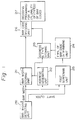
- Figure 1 is a diagram showing a basic construction of a bar code reader embodying the present invention.
- reference numeral 210 denotes a bar width detecting unit
- 211 denotes a bar width storing unit
- 212 denotes an address generating unit
- 213 denotes a fast screening unit
- 214 denotes a type of bar code determining unit
- 215 denotes an address & type storing unit
- 216 denotes a bar code decoding unit
- 217 denotes a decoding program(s) for a (plurality of) type(s) of bar codes.
- the bar width detecting unit 210 successively detects and outputs widths of the signals corresponding to the scanning of black bars and white spaces, respectively.
- the output of the bar width detecting unit 210 is stored in the bar width storing unit 211, where the address for storing the widths is generated by the address generating unit 212.
- the type of bar code detecting unit 214 detects a type of bar code, the widths of elements of which are detected by the above bar width detecting unit, based on the detected widths when the fast screening unit determines that the above set of successive widths satisfies the above predetermined necessary condition, and the detected type of bar code is stored in the address & type storing unit 215, together with information on the above addresses generated by the address generating unit for the widths of the bar code.
- the bar code decoding unit 216 is provided with a plurality of specific type decoding units (programs 217) for respectively decoding a plurality of types of bar codes.
- the bar code decoding unit 216 reads the above widths stored in the above bar width storing unit from the addresses indicated by the information stored in the address & type storing unit, and decodes the bar code constituted by the widths using one of the above specific type decoding unit corresponding to the type which is stored in the address & type storing unit 215 together with the above information.
- FIG. 2 is a diagram indicating a construction of a bar code reader with a hands-free scanner.
- the bar code reader with a hands-free scanner comprises an optical system and a control system.
- reference numeral 101 denotes a laser generating unit for generating a laser beam
- 102 denotes a laser control circuit for controlling the laser generating unit 101
- 103 denotes an optical unit for scanning a bar code with the laser beam by using a rotating polygon mirror
- 104 denotes a motor for rotating the polygon mirror
- 105 denotes an optical detector for receiving a laser beam reflected at the bar code
- 106 denotes an amplifier for amplifying an output of the optical detector 105
- 107 denotes an analog to digital converter for converting an analog output of the amplifier 106 to a digital value
- 108 denotes an LED lamp for indicating status of the bar code reader
- 109 denotes a speaker for notifying an operator that a bar code has been read.
- the control system
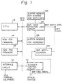
- FIG. 3 is a diagram indicating a construction of the control system in Fig. 2, according to an embodiment of the present invention.
- 113 denotes a CPU
- 114 denotes a ROM for storing firmware
- 115 denotes a RAM for storing firmware.
- the CPU 113 carries out an operation for decoding a bar code, controlling the optical system, and controlling a communication with the POS terminal equipment through the interface circuit 112.
- the digital output of the analog to digital converter 107 in Fig. 2, which is denoted by "BAR CODE SIGNAL" is binary, i.e., "1" while the laser beam is directed on a black bar, and "0" while the laser beam is directed on a white space.
- the bar width counter 122 counts, as a bar width, each duration in which the value of the BAR CODE SIGNAL is continuously “0" or “1” using a clock signal of a constant frequency. Thus, successive data respectively indicating widths of bars and spaces scanned with the laser beam are output from the bar width counter 122 corresponding to the respective bars and spaces.
- the bar width counter 122 also outputs a shift clock signal synchronizing with each of the above data.
- the data denoted by "BAR WIDTH DATA" in Fig. 3, is stored in the buffer memory 124.
- the above bar width data is also supplied to the bar code detection logic circuit 123 together with the shift clock signal.
- the construction comprised of the bar code detection logic circuit 123 and the buffer memories 124 and 125 realizes the functions in the various embodiments of the present invention as explained hereinafter.
- the basic function of the bar code detection logic circuit 123 is to detect a set of successive bar width data which satisfies a predetermined necessary condition for the set constituting a complete bar code, among bar width data supplied from the bar width counter 122.
- the scanning of a bar code with the laser beam are carried out successively in a plurality of paths in various directions.
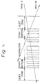
- Figure 4 indicates two typical paths of the scanning laser beam. In Fig.
- the laser beam scans all bars and spaces constituting a complete bar code, but in the path B, the laser beam scans only a portion of bars and spaces constituting a complete bar code.
- the output of the bar width counter 122 contains bar width data corresponding to a path of the laser beam in which a complete bar code is not scanned. Further, the laser beam may scan a character or a figure which may be printed near the bar code. Thus, only a part of the successive output of the bar width counter 122 corresponds to a scanned result of a complete bar code.
- the bar code detection logic circuit 123 when a set of successive bar width data satisfying the necessary condition for a complete bar code is detected by the bar code detection logic circuit 123, the addresses of start and stop codes of the set are memorized in the buffer memory 125.
- a bar code detection logic circuit 123 constructed to detect only a predetermined type (kind) of bar code among complete bar codes of various standards, may be provided for each type of bar code to be detected. Or the same bar code detection logic circuit 123 may be constructed to detect only a set of a plurality of predetermined types (kinds) of bar codes among complete bar codes of various standards. In the latter case, the above addresses are stored in the buffer memory 125 with information on the type of the detected bar code. Alternatively, the addresses may be stored in different areas corresponding to the types of the detected bar codes. Further, the bar code detection logic circuit 123 can discard a set of bar width data which is identical with a set of bar width data already stored in the buffer memory 124 during an operation to read a bar code.
- the amount of bar width data stored in the buffer memory 124 is considerably reduced compared with a total amount of the output of the bar width counter 122, so that the decoding of the bar width data stored in the buffer memory 124 can be carried out relatively slowly (compared with the hardware logic circuit) by software.
- the CPU 113 reads the above bar width data from the buffer memory 124 using the addresses (and information on the type of the bar code), and decodes the bar code in accordance with a decoding program (corresponding to the type of the bar code) stored in the ROM 114 and loaded on the RAM 115.
- Figure 5 is a diagram indicating a structure of a bar code symbol of CODE39.
- the bar code symbol contains start and stop characters, data portion, and start and end margins.
- the output of the analog to digital converter 107 of Fig. 2 indicates the levels corresponding to the start margin, the start character, the data portion, the stop character, and the end margin in turn as indicated in Fig. 6.
- the level of the output of the analog to digital converter 107 of Fig. 2 changes corresponding to the end margin, the stop character, the data portion, the start character, and the start margin in turn.
- the widths of the start and end margins are about 3.5 to 10 times the widths of the other elements in the start and end characters, and the other characters in the data portions. Therefore, the start and end margins can be detected by monitoring these widths as explained below.
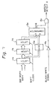
- Figures 7 and 8 are block diagrams respectively indicating constructions of margin detection circuits.
- the circuit of Fig.7 detects a situation wherein the laser beam scans a margin and then characters
- Figure 8 detects a situation wherein the laser beam scans characters and then a margin.
- reference numerals 11a, 11b, 11c, 11d, 11e, and 11f each denote a register for latching a bar width data
- 12a and 12b each denote a multiplier for multiplying a bar width data by N
- 13a and 13b each denote a comparator.
- the shift clock signal is a clock signal synchronizing with the bar width data
- the black/white signal indicates whether or not the element is black or white.
- the comparator 13a compares ⁇ the bar width data latched in the register 11c ⁇ with ⁇ 3.5 ⁇ (the bar width data latched in the register 11a) ⁇ . Since the widths of the start and end margins are more than 3.5 times larger than the width of any element of a character in the case of CODE39, when a width data of a margin is latched in the register 11c, and a bar width data of an element in a character is latched in the register 11a, the comparator 13a outputs an active signal.
- the AND gate 15a and the inverter 14a are provided for confirming that the output of the register 11c corresponds to a white margin.
- the output of the AND gate 15a which is denoted by MARGIN DETECT A, is active when the laser beam scans a margin and then characters.
- the comparator 13b compares ⁇ 3.5 ⁇ (the bar width data latched in the register 11f) ⁇ with ⁇ the bar width data latched in the register 11d ⁇ . Since the widths of the start and end margins are more than 3.5 times larger than the width of any element of a character in the case of CODE39, when width data of a margin is latched in the register 11d, and bar width data of an element in a character is latched in the register 11f, the comparator 13b outputs an active signal.
- the AND gate 15b and the inverter 14b are provided for confirming that the output of the register 11d corresponds to a white margin.
- the output of the AND gate 15b which is denoted by MARGIN DETECT B, is active when the laser beam scans characters and then a margin.
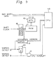
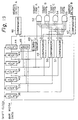
- Figure 9 is a block diagram indicating a construction for realizing the bar code detection logic circuit 123 and the buffer memories 124 and 125 in Fig. 3 in a first embodiment of the present invention.
- reference numeral 16 denotes a multiplexer
- 17 denotes a RAM
- 18 denotes an address counter
- 19 denotes an address latch circuit
- 20 denotes a flip flop circuit
- 21 denotes an AND gate.
- the RAM 17 corresponds to the buffer memory 124 in Fig. 3
- the address latch circuit 19 corresponds to the buffer memory 125 in Fig. 3.
- the output of the flip flop circuit 20 is applied to one input terminal of the AND gate 21, and the MARGIN DETECT B signal from the construction of Fig. 8 is applied to the other input terminal of the AND gate 21.
- the MARGIN DETECT A signal becomes active
- the MARGIN DETECT B signal becomes active, i.e., the laser beam scans a margin, then characters, and again a margin, and the output of the AND gate 21 becomes active.
- the active output of the AND gate 21 is supplied to the CPU 113 as a CPU interrupt signal.
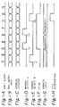
- Figure 10 indicates the operation of the construction of Fig. 9.
- bar width data and the shift clock signal are supplied to the construction of Fig. 9, and the address for storing the bar width data in the RAM 17 is generated synchronizing with the shift clock.
- the flip flop circuit 20 is reset.
- the MARGIN DETECT A signal becomes active at the time t2
- the flip flop circuit 20 is set, and the output of the address counter 18 is latched in the address latch circuit 19.
- the MARGIN DETECT A signal becomes active again, and thereby a new output of the address counter 18 is latched in the address latch circuit 19.
- the MARGIN DETECT B signal becomes active at the time t4, and thereby the output of the AND gate 21 becomes active to supply a CPU interrupt signal to the CPU 113.
- the CPU 113 When the CPU 113 receives the CPU interrupt signal, the CPU 113 reads a set of successive bar width data probably corresponding to a bar code, which is stored in the RAM 17 in the addresses beginning with the address output from the address latch circuit 19, through the multiplexer 16, and decodes the bar code in accordance with a bar code decoding program.
- the construction of Fig. 9 cannot necessarily select a set of successive bar width data corresponding to a bar code only.
- the detection of the MARGIN DETECT A signal followed by the detection of the MARGIN DETECT B signal is a necessary condition for detecting a complete bar code, and therefore, a lot of imperfect data supplied from the bar width counter 122 of Fig. 3 can be screened out by the construction of Fig. 9.
- Figure 11 indicates examples of the CODE39 characters.
- the bar codes for the characters "1" and “M” are shown.
- each character is represented by five black and four white elements, and each thick element represents “1" and each thin element represents "0".
- an average width of the nine elements may be used as a threshold value.
- a pattern comprised of "1" and "0” is obtained, and the pattern is compared with a table of patterns to determine the character the pattern represents.
- the CPU 113 carries out the above operation for all character patterns in a bar code
- the decoding operation is completed.
- the program for carrying out the above operation is stored in the ROM 114 in Fig. 3.
- the bar code reader of Fig. 2 informs the operator of the completion of the decoding operation by using the LED 108 or the speaker 109 of Fig.2, and the decoded data is transferred through the interface circuit 112 to the POS terminal equipment.
- Figure 12 is a block diagram indicating a construction for realizing the bar code detection logic circuit 123 and the buffer memories 124 and 125 in Fig. 3 in the second embodiment.
- reference numerals 701 to 70N each denote a bar code detection logic circuit
- 90 denotes an address memorizing circuit
- all the other elements denoted by the same reference numerals as shown in the other figures respectively indicate the same elements.
- the bar code detection logic circuits 701 to 70N realizes the bar code detection logic circuit 123 in Fig. 3, and the address memorizing circuit 90 comprises a buffer memory corresponding to the buffer memory 125 in Fig. 3 and an address latch circuit similar to the address latch circuit 19 of Fig. 9.
- Each of the bar code detection logic circuits 701 to 70N corresponds to a specific type of bar code, and determines whether or not bar width data successively output from the bar width counter 122 satisfies a predetermined necessary condition for a bar code of the type corresponding to the bar code detection logic circuit.
- Each of the bar code detection logic circuits 701 to 70N comprises the margin detection circuits of Figs. 7 and 8 for the corresponding type of bar code, the construction comprised of the flip flop circuit 20 and the AND gate 21 of Fig. 9, and the other construction for determining the satisfaction of the above predetermined necessary condition.
- the bar code detection logic circuit When the output of the AND gate 21 becomes active, and the above predetermined necessary condition is determined to be satisfied, the bar code detection logic circuit outputs an active signal.
- each of the bar code detection logic circuits 701 to 70N becomes active when the bar code detection logic circuit detects a bar code of the type corresponding to the circuit, and the outputs of the bar code detection logic circuits 701 to 70N are supplied to the address memorizing circuit 90.
- the output of the above address counter is applied to the above address latch circuit, and the output of the address latch circuit is stored in the above buffer memory in the address memorizing circuit 90, together with the above outputs of the bar code detection logic circuits 701 to 70N.
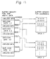
- the buffer memory in the address memorizing circuit 90 stores information on the type of the detected bar code, and the top address of an area in which the bar width data of the bar code is stored in the buffer memory 124 (RAM 17).
- Fig. 13 the addresses for storing the bar width data of bar codes of type #1 are stored in the area 1 of the buffer memory in the address memorizing circuit 90, and the addresses for storing the bar width data of bar codes of type #2 are stored in the area 2 of the buffer memory in the address memorizing circuit 90.
- the outputs of the bar code detection logic circuits 701 to 70N may be used as a part (of bits) of an address of the buffer memory in the address memorizing circuit 90 for storing the above address from the address latch circuit, and the other bits of the address of the buffer memory in the address memorizing circuit 90 can be generated by an address counter (not shown) provided corresponding to each of the bar code detection logic circuits 701 to 70N, and the address of the address counter is incremented by the active output of the corresponding bar code detection logic circuit.
- the ROM 114 stores decoding programs for all the types of bar codes corresponding to the above bar code detection logic circuits 701 to 70N, and the CPU 113 reads the above content of the address memorizing circuit 90, reads the bar width data stored in the buffer memory 124 using the address stored in the address memorizing circuit 90, and decodes the bar width data using the decoding program for the type which is stored in the address memorizing circuit 90 together with the above address.
- Figure 14 is a block diagram indicating a construction for realizing the bar code detection logic circuit 123 and the buffer memories 124 and 125 in Fig. 4 in the third embodiment.
- reference numerals 701' to 706' each denote a bar code detection logic circuit
- 711 to 716 each denote an AND gate
- 720 denotes a control gate
- 90' denotes an address memorizing circuit
- all the other elements denoted by the same reference numerals as shown in the other figures respectively indicate the same elements.
- the bar code detection logic circuits 701' to 706' correspond to the bar code detection logic circuits 701 to 70N in the construction of Fig. 12. In the construction of Fig.
- the bar code detection logic circuit 701' detects a bar code of UPC (Universal Product Code)
- the bar code detection logic circuit 702' detects a bar code of ITF (Interleaved 2 out of 5)
- the bar code detection logic circuit 703' detects a bar code of CODE39
- the bar code detection logic circuit 704' detects a bar code of CODE93
- the bar code detection logic circuit 705' detects a bar code of CODE128, and the bar code detection logic circuit 706 detects a bar code of NW7 (Narrow wide 7).
- the control register 720 and the AND gates 711 to 716 constitute a selector to pass an active output from only one of the bar code detection logic circuits 701' to 706'.
- the selection mode is preset in the control register 720 by the CPU 113. It is known that an incomplete scan result of a bar code of a type may accord with a complete scan result of another bar code of another type to cause an error. Therefore, such an erroneous detection may be prevented by the provision of the above selector.
- the address memorizing circuit 90' operates in the same way as the corresponding circuit 90 in Fig. 12.
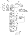
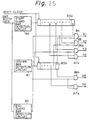
- Figure 15 is a block diagram indicating a construction for realizing the bar code detection logic circuit 123 and the buffer memories 124 and 125 and the buffer memories 124 and 125 in Fig. 3 in the fourth embodiment.
- reference numeral 19a and 19b each denote an address latch circuit
- 22 and 23 each denote a multiplexer
- 24 denotes a RAM
- 25 denotes a pulse generator
- 26 denotes a counter
- all the other elements denoted by the same reference numerals as shown in the other figures respectively indicate the same elements.
- the address output from the address counter 18 is applied to both the address latch circuits 19a and 19b, the MARGIN DETECT A signal is applied to the address latch circuit 19a to control the timing of latching the address applied thereto, and the MARGIN DETECT B signal is applied to the address latch circuit 19b to control the timing of latching the address applied thereto.
- the top address of the bar width data of each bar code stored in the RAM 17 is latched in the address latch circuit 19a
- the end address of the bar width data of each bar code stored in the RAM 17 is latched in the address latch circuit 19b.
- the output of the AND gate 21 is applied to the counter 26 to increment a count of the counter 26 which indicates the number of bar codes stored in the RAM 17 to be decoded by the CPU 113.
- the output of the AND gate 21 is also applied to the pulse generator 25.
- the pulse generator 25 receives the active output of the AND gate 21, the pulse generator 25 controls the multiplexer 23 to select the output of the multiplexer 22, controls the multiplexer 22 to select the outputs of the address latch circuits 19a and 19b in turn, and enables the RAM 24 to write the output of the multiplexer 23 therein.
- the output of the AND gate 21 becomes active, the top and end addresses of the bar width data of each bar code are stored in the RAM 24.
- the CPU 113 monitors the count of the counter 26. When the count is more than a predetermined number, the CPU 113 reads the top and end addresses from the RAM 24 through the multiplexer 23, reads the bar width data stored from the top address to the end address of the RAM 17 through the multiplexer 16, and decodes the bar code constituted by the bar width data.
- Figure 17 is a block diagram indicating a construction for realizing the bar code detection logic circuit 123 and the buffer memories 124 and 125 in Fig. 4 in the fifth embodiment.
- reference numeral 27 denote a counter
- 28 denotes a comparator
- 29 to 31 each denote an AND gate
- all the other elements denoted by the same reference numerals as shown in Fig. 9 respectively indicate the same elements.
- the counter 27 is incremented when each shift clock signal is applied thereto while the output of the flip flop circuit 20 becomes active.
- the CPU 113 presets a reference value which is equal to the number of elements in a bar code of a specific type, in the comparator 28.
- the comparator 28 compares the count of the counter 27 with the reference value, and makes one of its three outputs active according to whether the count is larger than the reference value, the count is equal to the reference value, or the count is smaller than the reference value.
- the three outputs of the comparator 28 are respectively applied to one of the input terminals of the AND gates 29 to 31. These AND gates receive the output of the AND gate 21 at the other input terminal thereof.
- the count of the counter 27 indicates the number of elements existing between the margins of the both sides of the bar code
- the three outputs of the comparator 28, or the outputs of the AND gates 29 to 31 indicate whether the count is larger than the reference value, the count is equal to the reference value, or the count is smaller than the reference value.
- the number of elements in each UPC bar code is constant, and ITF codes are generally used with a constant number of elements in each bar code.
- the minimum number of elements in each bar code is stipulated in the standards of CODE39, CODE93, CODE128, and Codabar (equivalent to NW7), as indicated in Table 1. Therefore, the examination of the number the elements in each bar code can be used as the aforementioned necessary condition the satisfaction of which is to be determined in the aforementioned bar code detection logic circuits in the construction of Figs. 12 and 14, and the construction of Fig. 16 is useful for the above determination.
- Fig. 17 may be used for the detection of the excess of the number of elements over the maximum number to prevent such data from being supplied to the CPU 113.
- Figure 17 is a block diagram indicating a construction for realizing the bar code detection logic circuit 123 and the buffer memories 124 and 125 in Fig. 3 in the sixth embodiment.
- the construction of Fig. 17 is provided to detect a bar code in which the number of elements between the margins is equal to L ⁇ p, or L ⁇ p+q where L, p, and q are each a predetermined integer.
- reference numeral 32 denotes a counter
- 32a denotes a flip flop circuit
- 33 denotes a pulse generation circuit
- 34 denotes a shift register
- 35 and 36 each denote an AND gate
- all the other elements denoted by the same reference numerals as shown in Fig. 9 respectively indicate the same elements.
- the CPU 113 applies a preset value L (which is explained below) to the counter 32, and the counter 32 sets the preset value therein when an active signal is output from the pulse generation circuit 33 thereto.
- the pulse generation circuit 33 outputs the active signal when the output of the flip flop circuit 20 rises, or when the count of the counter 32 reaches zero to output a carry output.
- the count of the counter 32 is decremented when an shift clock signal is applied thereto.
- the flip flop circuit 32a is set when the counter 32 outputs a carry output, and is reset when a next shift clock signal is applied thereto.
- the output of the flip flop circuit 32a is applied to one of the input terminals of the AND gate 35, and to a serial data input terminal of the shift register 34.
- the AND gate 35 receives the MARGIN DETECT B signal at the other input terminal of thereof.
- the serial data output of the shift register 34 is applied to one of the input terminals of the AND gate 36, and the MARGIN DETECT B signal is applied to the other input terminal of the AND gate 36.
- the active output of the flip flop circuit 20 triggers the pulse generation circuit 33 to preset the counter 32. Then, when L shift clocks are counted by the counter 32, the counter 32 outputs a carry output to set the flip flop circuit 32a, and trigger the pulse generator 33.
- the flip flop circuit 32a is immediately reset by the next shift clock, and the same operation is repeated until the MARGIN DETECT B signal is input to the construction of Fig. 18. If the timing at which the active MARGIN DETECT B signal is applied to the AND gate 35 coincides with the timing at which the output of the flip flop circuit 32a is active, the output of AND gate 35 becomes active, and the active output is sensed by the CPU 113. Namely, the CPU 113 recognizes that the number of elements in the bar code is equal to L ⁇ p.
- the shift register 34 contains q stages, and the contents of these stages are shifted by one stage when a shift clock is applied to the shift register 34. That is, an active output from the flip flop circuit 32a is output from the serial output terminal of the shift register 34 q shift clock cycles after an active signal is input into the serial input terminal thereof. Since the output of the flip flop circuit 32a becomes active L ⁇ p shift clock cycles after the first element of the bar code, the serial output of the shift register 34 becomes active L ⁇ p+q shift clock cycles after the first element of the bar code.
- the CPU 113 recognizes that the number of elements in the bar code is equal to L ⁇ p+q .
- Table 2 shows the above preset value L to be used for various types of bar codes. Since the number of elements in each character in the CODE39 bar codes is nine, and one space called an inter-character gap is inserted between each adjacent characters in the CODE39 bar codes, the preset value L is set as ten for the CODE39 bar codes. Similarly, since the number of elements in each character in the Codabar (NW7) bar codes is seven, and one inter-character gap is inserted between each adjacent characters in the Codabar (NW7) bar codes, the preset value L is set as eight for the Codabar (NW7) bar codes.
- the preset value L is set as six for the CODE93 and CODE128 bar codes.
- the number of elements in the stop character in the CODE93 and CODE128 bar codes is seven, and therefore the number q of stages in the shift register 34, is set to one for the CODE93 and CODE128 bar codes.
- Figure 18 is a block diagram indicating a construction for realizing the bar code detection logic circuit 123 and the buffer memories 124 and 125 in Fig. 3 in the seventh embodiment.
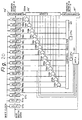
- the pattern detection circuit 37 is added to the construction of Fig. 9.
- the construction of the pattern detection circuit 37 in Fig. 18 according to the seventh embodiment is indicated in Fig. 19.
- the construction of Fig. 19 is provided to detect any of the three start codes A, B, and C, and the stop code of CODE128 in addition to the margin detect A signal and the margin detect B signal.
- reference numerals 38 to 44 each denote a latch circuit
- 45 denotes an adder
- 46 to 51 each denote a comparator
- 52 to 55 each denote an AND gate.
- the successive bar width data generated in the bar width counter 122 is supplied to the latch circuit 38, and latched therein synchronizing with the shift clock signal. Then, the latched bar width data is shifted through the series of latch circuits 38 to 44 one by one synchronizing with the shift clock signal. Namely, seven bar width data successively output from the bar width counter 122 are latched in the latch circuits 38 to 44.
- the adder 45 obtains a sum of the bar widths output from the six latch circuits 38 to 43. The number six is determined based on the number of elements in each character of CODE128.
- the output of the adder 45 indicates a length of a character following the margin
- the comparator 46 which compares the output of the latch circuit 44 with the output of the adder 45, outputs an active margin detect A signal.
- the output of the comparator 46 is not active. The detail of the comparator 46 is explained later with reference to Fig. 21.
- the output of the adder 45 indicates the length of a character preceding the margin
- the comparator 47 which compares the currently newest bar width data with the output of the adder 45, outputs an active margin detect B signal.
- the output of the comparator 47 is not active. The detail of the comparator 47 is explained later with reference to Fig. 21.
- the comparator 48 compares the output of the latch circuit 43 with the output of the latch circuit 41, and outputs a 48 ⁇ signal which indicates whether or not the output of the latch circuit 41 is smaller than the output of the latch circuit 43.
- the active START CODE A signal indicates that the START CODE A of CODE128 is detected.
- the active START CODE B signal indicates that the START CODE B of CODE128 is detected.
- the active START CODE C signal indicates that the START CODE C of CODE128 is detected.
- the active STOP CODE signal indicates that the STOP CODE of CODE128 is detected.
- Table 3 indicates the bar width patterns of the START CODE A, B, and C, and STOP CODE in CODE128, where each bar width is indicated by a multiple of a minimum bar width of an element, and Table 4 indicates the above four input signals of the AND gates 52 to 55.
- Figure 20 is a block diagram indicating a construction for detecting margins according to the eighth embodiment.
- the construction of Fig. 20 is provided to obtain the margin detect A signal and the margin detect B signal for the bar codes of CODE39, CODE93, CODE128, NW7, and ITF.
- reference numeral 45' denotes an adder
- 46' and 47' each denote a comparator
- 60 denotes a control register
- 61 denotes a multiplexer.
- the successive bar width data generated in the bar width counter 122 is supplied to the latch circuit 57a, and latched therein synchronizing with the shift clock signal. Then, the latched bar width data is shifted through the series of latch circuits 57a to 57c and 58a to 58n one by one synchronizing with the shift clock signal. Namely, seven bar width data successively output from the bar width counter 122 are latched in the latch circuits 57a to 57c and 58a to 58n. The outputs of the latch circuits 58a to 58m are applied through the corresponding AND gates 59a to 59m to the adder 45'.
- the adder 45' obtains a sum of the bar widths output from a predetermined portion of the latch circuits 58a to 58m, where the AND gates corresponding to the predetermined portion are made opened by the outputs of the control register 60.
- the control register 60 has a plurality of bits corresponding to the AND gates 59a to 59m, and the output of each bit is applied to one input terminal of the corresponding AND gate.
- the CPU 113 presets these bits of the control register 60 so that the above predetermined portion of the AND gates 59a to 59m are made opened.
- the predetermined portion is determined for the type of bar code as indicated in Table 5.
- each CODE39 character is constituted by nine elements
- each CODE93 or CODE128 character is constituted by six elements
- each NW7 character is constituted by seven elements.
- bar width data of ten successive elements near either of the margins on both sides of a bar code excluding the three elements nearest to the margin which correspond to a start or stop pattern are summed in the adder 45'.
- the comparator 46' compares the output of the latch circuit 58n with the output of the adder 45'. When the latch circuit 58n latches bar width data of a margin followed by a character, the comparator 46' outputs an active MARGIN DETECT A signal.
- the multiplexer 61 is provided to select bar width data which is to be applied to the comparator 47' for comparing with the output of the adder 45'.
- the multiplexer 61 selects an output of the latch circuit 58d.
- the multiplexer 61 selects an output of the latch circuit 58g.
- the multiplexer 61 selects an output of the latch circuit 58f.
- the multiplexer 61 selects the bar width data last supplied to the construction of Fig. 21, which is applied to the input side of the latch circuit 57a.
- the comparator 47 When the output of the multiplexer 61 is bar width data of a margin following a character, the comparator 47' outputs an active MARGIN DETECT B signal.
- Figure 21 is a diagram indicating a construction of the comparators 46 and 47 in Fig. 19 and 46' and 47' in Fig. 20.
- reference numerals 62 and 63 each denote a multiplier
- 64 denotes a comparator.
- n the multiplied quantities
- m the multiplied quantities
- Table 6 indicates preferable values of the above n and m, together with the lengths of margins to be detected, and the lengths of characters compared with the lengths of margins, respectively for CODE39, CODE93, CODE128, NW7, and ITF.
- Table 6 indicates effective threshold values realized by the above preferable values of n and m when comparing the above quantities a and b with the values n and m. All lengths are indicated by multiples of a minimum bar width X of an element.
- Figure 22 is a diagram indicating a construction of the comparators 48 to 51 in Fig. 19.
- reference numerals 65 to 68 each denote a multiplier
- 69 and 70 each denote a comparator
- 71 and 72 each denote an inverter
- 73 denotes an AND gate.
- a and b when comparing two quantities a and b in the construction of Fig. 22, one quantity a is multiplied by an integer l in the multiplier 65, and is multiplied by an integer m in the multiplier 68. Parallel to these multiplications, the other quantity b is multiplied by an integer n1 in the multiplier 66, and is multiplied by an integer n2 in the multiplier 67.
- the multiplied quantities l ⁇ a and n1 ⁇ b are compared in the comparator 69, and the multiplied quantities m ⁇ a and n2 ⁇ b are compared in the comparator 70, where l>m.
- the comparator 69 outputs an active signal d which indicates that it is determined the quantity a is larger than the quantity b.
- the comparator 70 outputs an active signal f which indicates that it is determined the quantity b is larger than the quantity a.
- the AND gate 73 outputs an active signal e which indicates that the quantities a and b are determined to be equal.
- Figure 23 is a diagram indicating a construction for detecting a bar code by detecting a start pattern and a stop pattern.
- reference numerals 74 denotes a start pattern detection circuit
- 75 denotes a stop pattern detection circuit
- 76 denotes a shift register
- 77 denotes an AND gate.
- the start pattern detection circuit 74, the stop pattern detection circuit 75, and the shift register 76, are provided according to the respective bar code types (standards). Namely, the number of stages in the shift register 76 is set so that the number is equal to the number of elements in a bar code symbol.
- the start pattern detection circuit 74 is designed to output an active signal when a start pattern (character) and a stop pattern, which are stipulated by the corresponding bar code standard, are scanned in the direction from a margin preceding the start or stop pattern.
- the stop pattern detection circuit 75 is designed to output an active signal when the above start pattern or stop pattern (character) is scanned in the direction from the pattern to a margin following the pattern.
- the output of the AND gate 77 becomes active when a bar code of the type to be detected is detected.
- a second bar code having a character length different from the full length of the shift register 76 may be detected by an active output of the above additional AND gate, where the number of stages from the input of the shift register 76 to the intermediate stage is set equal to the above character length of the above second bar code.
- Figure 24 is a diagram indicating a structure of JAN13 (equivalent to EAN13) as an example of the UPC codes.
- a UPC code comprises a blank portion called a left margin, a left guard bar, a center guard bar, a right guard bar, a right margin, six characters (called left block) between the left guard bar and the center guard bar, and six characters (called right block, and including one modulus check character) between the center guard bar and the right guard bar.
- the right block and the left block can be read independently.
- a modulus ten check is carried out for the characters in the sequence of the left and right blocks.
- a JAN13 code contains twelve characters, a thirteenth character is determined based on the pattern of the left block.
- the structure of a JAN8 (EAN8) code is similar to the above JAN13 code except that the number of the characters in each of the left and right blocks is equal to four.
- Figure 25 is a block diagram indicating a construction for realizing the bar code detection logic circuit 123 and the buffer memories 124 and 125 in Fig. 3 in the tenth embodiment.
- the construction of Fig. 25 is provided to detect the UPC codes.
- reference numeral 80 denotes a start guard bar detection circuit
- 81 denotes a center guard bar detection circuit
- 82 denotes an end guard bar detection circuit
- 83a and 83b each denote a shift register
- 84 to 87b each denote an AND gate.
- start guard bar means a guard bar which is detected following a margin
- the above "end guard bar” means a guard bar which is detected preceding a margin.
- the center guard bar is located at the center of symmetry.
- the start guard bar detection circuit 80 detects the above start guard bar
- the center guard bar detection circuit 81 detects the above center guard bar
- the end guard bar detection circuit 82 detects the above end guard bar.
- the shift register 83a contains a plurality of stages corresponding to a total number of elements between the left and right margins in a UPC code (corresponding to a full length of a JAN13 bar code)
- the shift register 83b contains a plurality of stages corresponding to the number of elements before the center guard bar in a UPC code.
- the shift register 83a has four output terminals respectively denoted by g, h, i, and k, where the output terminal k corresponds to the full length of a JAN13 code, the output terminal i corresponds to the full length of a JAN8 code, and the output terminal h corresponds to the length from the start guard bar to the center guard bar in a JAN13 code, and the output terminal g corresponds to the length from the start guard bar to the center guard bar in a JAN8 code.
- the shift register 83b has three output terminals respectively denoted by t, r, and s.
- the output terminal s corresponds to the length from the center guard bar to the end guard bar in a JAN13 code
- the output terminal r corresponds to the length from the start guard bar to the center guard bar in a JAN8 code
- the output terminal t corresponds to the length from the center guard bar to the end guard bar in a JAN8 code.
- the AND gate 84 receives the output from the terminal k in the shift register 83a, the output of the end guard bar detection circuit 82, and the output from the terminal s of the shift register 83b.
- the AND gate 84 outputs an active signal S1 when a start guard bar, a center guard bar, an end guard bar of a JAN13 code are detected
- the AND gate 85 outputs an active signal S2 when a start guard bar, a center guard bar, and an end guard bar of a JAN8 code are detected
- the AND gate 86a outputs an active signal S3 when a start guard bar and a center guard bar of a JAN13 code are detected
- the AND gate 87a outputs an active signal S4 when a start guard bar and a center guard bar of a JAN8 code are detected
- the AND gate 86b outputs an active signal S5 when a center guard bar and an end guard bar of a JAN13 code are detected
- the AND gate 87b outputs an active signal S6 when a center guard bar and an end guard bar of a JAN8 code are detected.
- the above detection signals S1 to S6 are supplied to the CPU 113. These signals may be used by the CPU 113 as status flags when reading the UPC codes.
Landscapes
- Engineering & Computer Science (AREA)
- Physics & Mathematics (AREA)
- Artificial Intelligence (AREA)
- General Health & Medical Sciences (AREA)
- Toxicology (AREA)
- Electromagnetism (AREA)
- Health & Medical Sciences (AREA)
- Computer Vision & Pattern Recognition (AREA)
- General Physics & Mathematics (AREA)
- Theoretical Computer Science (AREA)
- Quality & Reliability (AREA)
- Printers Characterized By Their Purpose (AREA)
- Character Input (AREA)
Claims (19)
- Lecteur de code barres pour une utilisation avec un scanner haute vitesse, comprenant :un moyen de réception pour recevoir depuis un tel scanner haute vitesse un signal de balayage produit en balayant une surface d'un article sur laquelle un code barres comprenant une pluralité d'éléments est imprimé, le signal de balayage étant modifié entre des premier et second niveaux respectifs en fonction de si des parties de la surface qui est balayée sont en noir ou en blanc ;un moyen de détection de largeur de barre (122) pour détecter et émettre en sortie successivement des valeurs de largeur, chacune de ces valeurs de largeur représentant une durée pendant laquelle le niveau de signal de balayage est non modifié ;un moyen de stockage de largeur de barre (124) pour stocker les valeurs de largeur détectées par le moyen de détection de largeur de barre ; etun moyen de génération d'adresse (18) pour générer une adresse au niveau de laquelle chacune des valeurs de largeur doit être stockée dans ledit moyen de stockage de largeur de barre (124),
caractérisé par :un moyen de détection de type de code barres (701 - 70N ; 701'-706') pour déterminer si oui ou non un jeu de valeurs de largeur détectées successivement par le moyen de détection de largeur de barre satisfait à une condition nécessaire prédéterminée pour le jeu de valeurs de largeur afin de représenter un code barres complet d'une pluralité de types prédéterminés de codes barres lisibles par le lecteur de code barres et s'il en est ainsi, pour détecter le type de code barres représenté par le jeu de valeurs de largeur concerné ;un moyen de stockage d'adresse et de type (90) pour stocker une information qui identifie le type de code barres représenté par ce jeu et qui identifie également les adresses générées par le moyen de génération d'adresse (18) pour des valeurs de largeur de ce jeu ; etun moyen de décodage de code barres (113, 114, 115) permettant de décoder un jeu de valeurs de largeur représentant chacun de ladite pluralité prédéterminée de types de codes barres lisibles par le lecteur de code barres et activés, suite à la détermination consistant en ce qu'un tel jeu de valeurs de largeur satisfait ladite condition prédéterminée, pour utiliser ladite information stockée pour ce jeu afin de décoder les valeurs de largeur de ce jeu d'une manière appropriée pour son type détecté de code barres. - Lecteur de code barres selon la revendication 1, dans lequel ladite condition nécessaire prédéterminée est déterminée comme ayant été satisfaite lorsque, dans le jeu de valeurs de largeur, tout d'abord des valeurs de largeur correspondant à une marge suivie par des caractères sont identifiées et qu'ensuite dans le jeu, des valeurs de largeur correspondant à des caractères suivis par une marge sont identifiées.
- Lecteur de code barres selon la revendication 1 ou 2, dans lequel ledit moyen de détection de type de code barres (701 - 70N ; 701' - 706') est réalisé à l'aide d'un circuit logique constitué par des composants matériels et ledit moyen de décodage de code barres est réalisé au moyen d'un logiciel.
- Lecteur de code barres selon la revendication 1, 2 ou 3, dans lequel ledit moyen de détection de type de code barres (701 - 70N ; 701' - 706') comprend une pluralité de circuits logiques de détection de code barres (701 - 70N ; 701' - 706'), chacun pour détecter un code barres de l'un desdits types prédéterminés.
- Lecteur de code barres selon la revendication 4, comprenant en outre un moyen de sélecteur (711 - 716, 720) pour sélectionner l'un de ladite pluralité de circuits logiques de détection de code barres (701' - 706').
- Lecteur de code barres selon l'une quelconque des revendications précédentes, dans lequel ledit moyen de stockage d'adresse et de type (90) contient une pluralité de zones correspondant respectivement à ladite pluralité de types prédéterminés de codes barres lisibles par le lecteur.
- Lecteur de code barres selon l'une quelconque des revendications précédentes, dans lequel ledit moyen de détection de type de code barres (701 - 70N) comprend :un premier moyen de détection de marge (11a - 15a) pour détecter une largeur de barre correspondant à une première marge émise en sortie depuis ledit moyen de détection de largeur de barre ; etun second moyen de détection de marge (11d - 15b) pour détecter une largeur de barre correspondant à une seconde marge émise en sortie depuis ledit moyen de détection de largeur de barre, qui suit une largeur de barre correspondant à un élément dans ledit code barres.
- Lecteur de code barres selon la revendication 7, dans lequel ledit moyen de détection de type de code barres (701 - 70N) comprend en outre un moyen de détection de marge sur les deux côtés (20) fonctionnant pour produire un signal de détection suite à une détection de la largeur de barre correspondant à ladite seconde marge après la détection de la largeur de barre correspondant à ladite première marge.
- Lecteur de code barres selon la revendication 8, dans lequel ledit moyen de détection de type de code barres (701 - 70N) comprend en outre un moyen de génération d'interruption (21) pour générer un signal d'interruption destiné à être appliqué sur ledit moyen de décodage de code barres (113, 114, 115) lorsque ledit moyen de détection de marge sur les deux côtés produit un tel signal de détection.
- Lecteur de code barres selon la revendication 9, dans lequel ledit moyen de détection de type de code barres (701 - 70N) comprend en outre un moyen d'indication d'interruption (26) pour indiquer le nombre desdits signaux d'interruption qui ont été générés par ledit moyen de génération d'interruption (21) et dont les codes barres correspondants respectifs n'ont pas été décodés par ledit moyen de décodage de code barres (113, 114, 115).
- Lecteur de code barres selon la revendication 9 ou 10, comprenant en outre :un premier moyen de verrouillage d'adresse (19a) pour verrouiller l'adresse générée par ledit moyen de génération d'adresse (18) lorsque ledit premier moyen de détection de marge (11a - 15a) détecte la largeur de barre correspondant à ladite première marge ;un second moyen de verrouillage d'adresse (19b) pour verrouiller l'adresse générée par ledit moyen de génération d'adresse (18) lorsque ledit second moyen de détection de marge (11d - 15b) détecte la largeur de barre correspondant à ladite seconde marge ; etun moyen de mémorisation d'adresse (24) pour stocker lesdites adresses verrouillées dans lesdits premier et second moyens de verrouillage d'adresse (19a, 19b) lorsque ledit signal d'interruption est généré par ledit moyen de génération d'interruption (21).
- Lecteur de code barres selon la revendication 8, comprenant en outre un moyen de comptage de nombre d'éléments (27) pour compter un nombre d'éléments pour lesquels lesdites largeurs de barre sont émises en sortie depuis ledit moyen de détection de largeur de barre (122) après que ledit premier moyen de détection de marge (11a - 15a) a détecté la largeur de barre correspondant à ladite première marge jusqu'à ce que ledit second moyen de détection de marge (11d - 15b) détecte la largeur de barre correspondant à ladite seconde marge.
- Lecteur de code barres selon la revendication 12, comprenant en outre un moyen de comparaison de nombre d'éléments (28) pour comparer ledit nombre d'éléments compté par ledit moyen de comptage de nombre d'éléments (27) à une valeur de référence prédéterminée.
- Lecteur de code barres selon la revendication 7, comprenant en outre :un moyen de comptage de longueur unitaire (32) pour compter un nombre d'éléments pour lesquels lesdites largeurs de barre sont émises en sortie depuis ledit moyen de détection de largeur de barre (122) après que ledit premier moyen de détection de marge (11a - 15a) a détecté la largeur de barre correspondant à ladite première marge et pour détecter un instant auquel ledit nombre atteint un multiple arbitraire (PL) d'un nombre prédéterminé (L) ; etun moyen de détection de coïncidence (35) pour détecter une coïncidence entre ledit instant détecté par ledit moyen de comptage de longueur unitaire (32) et un instant auquel ledit second moyen de détection de marge (11d - 15b) détecte la largeur de barre correspondant à ladite seconde marge.
- Lecteur de code barres selon la revendication 7 ou 14, comprenant en outre :un moyen de comptage de longueur d'éléments (32, 32a, 34) pour compter un nombre d'éléments pour lesquels lesdites largeurs de barre sont émises en sortie depuis ledit moyen de détection de largeur de barre (122) après que ledit premier moyen de détection de marge (11a - 15a) a détecté la largeur de barre correspondant à ladite première marge et pour détecter un instant auquel ledit nombre atteint une somme (PL + q) d'un multiple arbitraire (PL) d'un premier nombre prédéterminé (L) et d'un second nombre prédéterminé (q) ; etun moyen de détection de coïncidence (36) pour détecter une coïncidence entre ledit instant détecté par ledit moyen de comptage de longueur d'éléments (32, 32a, 34) et un instant auquel ledit second moyen de détection de marge (11d - 15b) détecte la largeur de barre correspondant à ladite seconde marge.
- Lecteur de code barres selon la revendication 8, dans lequel ledit moyen de détection de type de code barres (701 - 70N) comprend en outre :un moyen de registre à décalage (38 - 44) comportant une série d'étages pour recevoir l'une après l'autre des largeurs de barre émises en sortie successivement depuis ledit moyen de détection de largeur de barre (122) et pour décaler les largeurs de barre reçues au travers des étages de la série chaque fois que le moyen de détection de largeur de barre (122) émet en sortie une largeur de barre et pour émettre en sortie en parallèle les largeurs de barre respectives contenues dans les étages de la série ;un premier moyen de comparateur (48 - 51) pour comparer les unes avec les autres les largeurs de barre respectives qui sont émises en sortie depuis les étages de numéros impairs de ladite série ; etun second moyen de comparateur (48 - 51) pour comparer les unes avec les autres les largeurs de barre respectives qui sont émises en sortie depuis les étages de numéros pairs de ladite série.
- Lecteur de code barres selon la revendication 8, dans lequel ledit moyen de détection de type de code barres (701 - 70N) comprend en outre :un moyen de registre à décalage (57a - 58n) comportant une série d'étages pour recevoir l'une après l'autre des largeurs de barre émises en sortie successivement depuis ledit moyen de détection de largeur de barre (122) et pour décaler les largeurs de barre reçues au travers des étages de la série chaque fois que le moyen de détection de largeur de barre (122) émet en sortie une largeur de barre et pour émettre en sortie en parallèle les largeurs de barre respectives contenues dans les étages de la série ; etun moyen d'additionneur (45') pour obtenir une somme de sorties respectives d'étages successifs prédéterminés de ladite série (57a - 58n) ;un premier moyen de comparateur (46') pour comparer une sortie en provenance de l'étage final de ladite série avec ladite somme ; etun second moyen de comparateur (47') pour comparer une sortie d'un autre étage de ladite série avec ladite somme.
- Lecteur de code barres selon l'une quelconque des revendications 1 à 6, dans lequel ledit moyen de détection de type de code barres (701 - 70N) comprend :un moyen de détection de motif de début (74) pour détecter un premier motif de largeurs de barre successives qui indique un emplacement d'un premier caractère d'un code barres et pour émettre en sortie une première sortie active lorsque ledit premier motif est détecté ;un moyen de détection de motif d'arrêt (75) pour détecter un second motif de largeurs de barre successives qui indique un emplacement d'un dernier caractère d'un code barres et pour émettre en sortie une seconde sortie active lorsque ledit second motif est détecté ;un moyen de retard (76) pour retarder ladite première sortie active d'un temps correspondant à un nombre prédéterminé d'éléments entre lesdits premier et second motifs dans un code barres de l'un desdits types prédéterminés ; etun moyen de détection de coïncidence (77) pour détecter une coïncidence entre la première sortie active retardée par ledit moyen de retard (76) et ladite seconde sortie active.
- Lecteur de code barres selon l'une quelconque des revendications 1 à 6 et 18, dans lequel ledit moyen de détection de type de code barres (701 - 70N) comprend :un moyen de détection de barre de garde de début (80) pour détecter un premier motif de largeurs de barre successives qui indique un emplacement d'un premier caractère d'un code barres et pour émettre en sortie une première sortie active lorsque ledit premier motif est détecté ;un moyen de détection de barre de garde d'arrêt (82) pour détecter un second motif de largeurs de barre successives qui indique un emplacement d'un dernier caractère d'un code barres et pour émettre en sortie une seconde sortie active lorsque ledit second motif est détecté ;un moyen de détection de barre de garde de centre (81) pour détecter un troisième motif de largeurs de barre successives qui indique un centre entre lesdits premier et second motifs et pour émettre en sortie une troisième sortie active lorsque ledit troisième motif est détecté ;un premier moyen de retard (83a) pour retarder ladite première sortie active d'un temps correspondant à un premier nombre prédéterminé d'éléments entre lesdits premier et second motifs dans un code barres de l'un desdits types prédéterminés et pour émettre en sortie un premier signal actif retardé ;un second moyen de retard (83a) pour retarder ladite première sortie active d'un temps correspondant à un second nombre prédéterminé d'éléments entre lesdits premier et second motifs dans un code barres dudit type considéré et pour émettre en sortie un second signal actif retardé ;un troisième moyen de retard (83b) pour retarder ladite troisième sortie active d'un temps correspondant à un troisième nombre prédéterminé d'éléments entre lesdits troisième et second motifs dans un code barres dudit type considéré et pour émettre en sortie un troisième signal actif retardé ;un premier moyen de détection de coïncidence (84) pour détecter une coïncidence dudit premier signal actif retardé avec ledit second signal actif ;un second moyen de détection de coïncidence (86a) pour détecter une coïncidence dudit second signal actif retardé avec ledit troisième signal actif ; etun troisième moyen de détection de coïncidence (86b) pour détecter une coïncidence dudit troisième signal actif retardé avec ledit second signal actif.
Applications Claiming Priority (6)
| Application Number | Priority Date | Filing Date | Title |
|---|---|---|---|
| JP1671991 | 1991-02-08 | ||
| JP3016719A JP2734781B2 (ja) | 1991-02-08 | 1991-02-08 | バーコード読取装置 |
| JP16719/91 | 1991-02-08 | ||
| JP23228/91 | 1991-02-18 | ||
| JP3023228A JP2776035B2 (ja) | 1991-02-18 | 1991-02-18 | バーコード読取装置 |
| JP2322891 | 1991-02-18 |
Publications (3)
| Publication Number | Publication Date |
|---|---|
| EP0498678A2 EP0498678A2 (fr) | 1992-08-12 |
| EP0498678A3 EP0498678A3 (fr) | 1998-01-21 |
| EP0498678B1 true EP0498678B1 (fr) | 2000-05-10 |
Family
ID=26353118
Family Applications (1)
| Application Number | Title | Priority Date | Filing Date |
|---|---|---|---|
| EP92301090A Expired - Lifetime EP0498678B1 (fr) | 1991-02-08 | 1992-02-10 | Lecteur de code à barres à vitesse de balayage élevée apte à lire plus d'un type de code à barres |
Country Status (3)
| Country | Link |
|---|---|
| US (1) | US5414252A (fr) |
| EP (1) | EP0498678B1 (fr) |
| DE (1) | DE69231012T2 (fr) |
Families Citing this family (50)
| Publication number | Priority date | Publication date | Assignee | Title |
|---|---|---|---|---|
| US5468946A (en) * | 1994-04-29 | 1995-11-21 | Eastman Kodak Company | Method and apparatus for decoding multi-level bar codes or bi-level bar codes |
| US8261993B2 (en) | 1994-05-25 | 2012-09-11 | Marshall Feature Recognition, Llc | Method and apparatus for accessing electronic data via a familiar printed medium |
| US7712668B2 (en) * | 1994-05-25 | 2010-05-11 | Marshall Feature Recognition, Llc | Method and apparatus for accessing electronic data via a familiar printed medium |
| US7703683B2 (en) | 1994-05-25 | 2010-04-27 | Marshall Feature Recognition, Llc | Method and apparatus for accessing electronic data via a familiar printed medium |
| US8910876B2 (en) | 1994-05-25 | 2014-12-16 | Marshall Feature Recognition, Llc | Method and apparatus for accessing electronic data via a familiar printed medium |
| US6866196B1 (en) | 1994-05-25 | 2005-03-15 | Spencer A. Rathus | Method and apparatus for accessing electronic data via a familiar printed medium |
| US7717344B2 (en) * | 1994-05-25 | 2010-05-18 | Marshall Feature Recognition, Llc | Method and apparatus for accessing electronic data via a familiar printed medium |
| GB2291524B (en) * | 1994-07-21 | 1997-01-29 | Fujitsu Ltd | Reading bar codes |
| JP3083464B2 (ja) * | 1995-08-10 | 2000-09-04 | 富士通株式会社 | バーコード検出装置及び検出方法 |
| GB2305074A (en) * | 1995-08-31 | 1997-03-26 | Id Systems Ltd | Apparatus for Remotely Reading Data Storage Devices |
| JPH09179927A (ja) | 1995-12-26 | 1997-07-11 | Fujitsu Ltd | バーコード読取装置 |
| US5969325A (en) * | 1996-06-03 | 1999-10-19 | Accu-Sort Systems, Inc. | High speed image acquisition system and method of processing and decoding barcode symbol |
| US5903729A (en) * | 1996-09-23 | 1999-05-11 | Motorola, Inc. | Method, system, and article of manufacture for navigating to a resource in an electronic network |
| US8788432B2 (en) | 1996-10-02 | 2014-07-22 | Nintendo Of America Inc. | Method and apparatus for efficient handling of product return transactions |
| US6085172A (en) | 1996-10-02 | 2000-07-04 | Nintendo Of America Inc. | Method and apparatus for efficient handling of product return transactions |
| US6757663B1 (en) * | 1996-10-02 | 2004-06-29 | Nintendo Of America | Electronic registration system for product transactions |
| US8156026B2 (en) | 2000-05-12 | 2012-04-10 | Nintendo of America Ltd. | Method and apparatus for enabling purchasers of products to obtain return information and to initiate product returns via an on-line network connection |
| US7797164B2 (en) * | 1996-10-02 | 2010-09-14 | Nintendo Of America, Inc. | Method and apparatus for enabling purchasers of products to obtain return information and to initiate product returns via an on-line network connection |
| JPH10134130A (ja) * | 1996-10-28 | 1998-05-22 | Fujitsu Ltd | バーコード読取方法およびバーコード読取装置 |
| GB2326250A (en) * | 1997-05-22 | 1998-12-16 | Glynwed Pipe Systems Ltd | Reading barcodes for control of electrofusion welding |
| JPH1153465A (ja) * | 1997-08-08 | 1999-02-26 | Fujitsu Ltd | バーコード読取装置 |
| JP3576356B2 (ja) | 1997-08-08 | 2004-10-13 | 富士通株式会社 | バーコード読取装置,バーコード読取方法,及びコンピュータ可読媒体 |
| US6119941A (en) * | 1998-05-04 | 2000-09-19 | Intermec Ip Corp. | Automated help instructions for automatically or adaptively configuring a hand-held device, such as a bar code reader or hand-held personal computer |
| CA2350551A1 (fr) | 1998-11-13 | 2000-05-25 | Nintendo Of America Inc. | Procede et appareil pour verifier les operations de vente de produits et pour traiter les renvois de produits |
| US8510171B2 (en) | 2000-07-25 | 2013-08-13 | Nintendo Of America Inc. | Electronic product registration system with customizable return/warranty programs |
| US6592039B1 (en) | 2000-08-23 | 2003-07-15 | International Business Machines Corporation | Digital pen using interferometry for relative and absolute pen position |
| AU2002211572A1 (en) | 2000-10-10 | 2002-04-22 | Nintendo Of America Inc. | Voice recognition method and apparatus using model number lookup |
| US8682077B1 (en) | 2000-11-28 | 2014-03-25 | Hand Held Products, Inc. | Method for omnidirectional processing of 2D images including recognizable characters |
| US8209226B2 (en) * | 2001-11-15 | 2012-06-26 | Nintendo Of America Inc. | Non-serialized electronic product registration system and method of operating same |
| US8380690B2 (en) | 2003-08-28 | 2013-02-19 | International Business Machines Corporation | Automating form transcription |
| US7840439B2 (en) * | 2003-11-10 | 2010-11-23 | Nintendo Of America, Inc. | RF-ID product tracking system with privacy enhancement |
| JP4254724B2 (ja) * | 2005-02-16 | 2009-04-15 | 株式会社デンソーウェーブ | バーコード読取り方法及びコンピュータプログラム |
| US7451933B2 (en) * | 2005-04-19 | 2008-11-18 | Intermec Ip Corp. | Optoelectronic device, process and article for acquiring machine-readable symbols, such as bar codes |
| US7455230B2 (en) * | 2005-04-22 | 2008-11-25 | Nintendo Of America Inc. | UPC, EAN and JAN validation system and method for loss prevention at point of sale/return |
| WO2007022411A1 (fr) * | 2005-08-18 | 2007-02-22 | Cappella Inc. | Systeme de mise en place et procede d'utilisation pour le positionnement d'un dispositif dans une bifurcation |
| US20080052184A1 (en) * | 2006-08-22 | 2008-02-28 | Nintendo Of America Inc. | Systems and methods for product authentication and warranty verification for online auction houses |
| US20090150170A1 (en) * | 2007-12-11 | 2009-06-11 | Nintendo Of America | Method and apparatus for fraud reduction and product recovery |
| US20100325020A1 (en) * | 2008-12-04 | 2010-12-23 | Nintendo Of America, Inc. | Systems and/or methods for globally tracking items and generating active notifications regarding the same |
| US8302024B2 (en) | 2009-04-02 | 2012-10-30 | Nintendo Of America Inc. | Systems and/or methods for paging control including selective paging element display according to a binary subdivision and/or a serial progressive display approach |
| US20110016008A1 (en) * | 2009-07-14 | 2011-01-20 | Nintendo of America Inc., | Electronic registration systems for processing variable or multiple return/warranty policies, and associated methods |
| US10296916B2 (en) | 2009-09-11 | 2019-05-21 | Maridee Joy Maraz | System and/or method for handling recalled product purchases and/or return/warranty requests |
| US8239269B2 (en) * | 2009-09-11 | 2012-08-07 | Nintendo Of America Inc. | System and/or method for handling returns involving products tied to post-paid subscriptions/services |
| CN102034084B (zh) * | 2009-09-25 | 2013-03-06 | 神基科技股份有限公司 | 多类型条形码的辨识方法及条形码辨识装置 |
| US8712856B2 (en) | 2010-04-12 | 2014-04-29 | Nintendo Of America Inc. | Systems and/or methods for determining item serial number structure and intelligence |
| EP2393036B1 (fr) * | 2010-06-01 | 2016-03-02 | Fujian Newland Computer Co., Ltd. | Puce de décodage de code-barres |
| US8595062B2 (en) | 2010-11-15 | 2013-11-26 | Nintendo Of America Inc. | Systems and/or methods for fraud detection in award point programs |
| US8799111B2 (en) | 2012-05-04 | 2014-08-05 | Nintendo Of America Inc. | Systems and/or methods for selling non-inventory items at point-of-sale (POS) locations |
| WO2013179436A1 (fr) * | 2012-05-31 | 2013-12-05 | 株式会社オプトエレクトロニクス | Dispositif de lecture, procédé de sortie de résultat de lecture et programme associé |
| US9569769B2 (en) | 2012-09-17 | 2017-02-14 | E2Interactive, Inc. | Composite activation indicia substrate |
| US9412087B2 (en) | 2014-03-03 | 2016-08-09 | Aesynt Incorporated | System, method, and apparatus for mapping product identification to medication identification |
Family Cites Families (8)
| Publication number | Priority date | Publication date | Assignee | Title |
|---|---|---|---|---|
| US4044227A (en) * | 1975-08-07 | 1977-08-23 | The Upjohn Company | Bar code reader |
| JPS5631169A (en) * | 1979-08-24 | 1981-03-28 | Toshiba Corp | Bar code decoder |
| JPS6011973A (ja) | 1983-07-01 | 1985-01-22 | Nec Corp | バ−コ−ド読取装置 |
| JPS6210781A (ja) * | 1985-07-09 | 1987-01-19 | Alps Electric Co Ltd | バ−コ−ドリ−ダ |
| WO1988004456A1 (fr) * | 1986-12-12 | 1988-06-16 | Metrologic Instruments, Inc. | Lecteur de code a barres pourvu d'un numeriseur et d'un sequenceur |
| US4855581A (en) | 1988-06-17 | 1989-08-08 | Microscan Systems Incorporated | Decoding of barcodes by preprocessing scan data |
| US5189289A (en) * | 1989-05-17 | 1993-02-23 | Fujitsu Limited | Distinguishing bar code types by comparing bar block sizes |
| JP2761265B2 (ja) * | 1989-11-07 | 1998-06-04 | 富士通株式会社 | バーコード読取方式 |
-
1992
- 1992-02-10 US US07/833,493 patent/US5414252A/en not_active Expired - Lifetime
- 1992-02-10 DE DE69231012T patent/DE69231012T2/de not_active Expired - Fee Related
- 1992-02-10 EP EP92301090A patent/EP0498678B1/fr not_active Expired - Lifetime
Also Published As
| Publication number | Publication date |
|---|---|
| DE69231012D1 (de) | 2000-06-15 |
| US5414252A (en) | 1995-05-09 |
| EP0498678A3 (fr) | 1998-01-21 |
| DE69231012T2 (de) | 2000-09-28 |
| EP0498678A2 (fr) | 1992-08-12 |
Similar Documents
| Publication | Publication Date | Title |
|---|---|---|
| US5414252A (en) | High speed scan bar code reader which can read more than one type of bar code | |
| EP0647916B1 (fr) | Brochage pour balayage de code barré | |
| US5457308A (en) | Bar code scan stitching | |
| JP2616921B2 (ja) | ラベル識別装置 | |
| US5128527A (en) | Apparatus for reading a bar code | |
| US4868375A (en) | Method for changing the functions of a bar code reader | |
| US6321987B1 (en) | Bar code reading apparatus for reading plural code systems | |
| AU597443B2 (en) | Method and apparatus for bar code data autodiscrimination | |
| US5444231A (en) | Bar code scan stitching | |
| US5194722A (en) | Enhanced UPC bar code decoding system reconstructing complete bar code signals from partial bar code scans | |
| US4421978A (en) | Decoding method for multicharacter labels | |
| US5821520A (en) | Bar code scanning system with the pre-decoding signal processing and method for bar code candidate selection for decoding | |
| JPS61101880A (ja) | バ−コ−ド読取方法および装置 | |
| US6343742B2 (en) | Bar code reader and bar code reading method | |
| JPH0354388B2 (fr) | ||
| US4253018A (en) | Symbol decoding system | |
| EP0818019B1 (fr) | Procede et dispositif de decodage de codes a barres | |
| JP2971636B2 (ja) | バーコードシンボル読取装置 | |
| US5917172A (en) | Apparatus and method for bar code reading | |
| US6695210B2 (en) | Bar code reader and bar code reading method | |
| US5952643A (en) | Bar code decoder for a lightpen | |
| JP3785527B2 (ja) | バーコード読取装置、及び記憶媒体 | |
| JP2677805B2 (ja) | 符号読取装置 | |
| JP2750244B2 (ja) | バーコードデコーダのデコード方法 | |
| JP2853357B2 (ja) | バーコードリーダ |
Legal Events
| Date | Code | Title | Description |
|---|---|---|---|
| PUAI | Public reference made under article 153(3) epc to a published international application that has entered the european phase |
Free format text: ORIGINAL CODE: 0009012 |
|
| AK | Designated contracting states |
Kind code of ref document: A2 Designated state(s): DE FR GB |
|
| PUAL | Search report despatched |
Free format text: ORIGINAL CODE: 0009013 |
|
| AK | Designated contracting states |
Kind code of ref document: A3 Designated state(s): DE FR GB |
|
| 17P | Request for examination filed |
Effective date: 19980310 |
|
| 17Q | First examination report despatched |
Effective date: 19981013 |
|
| GRAG | Despatch of communication of intention to grant |
Free format text: ORIGINAL CODE: EPIDOS AGRA |
|
| GRAG | Despatch of communication of intention to grant |
Free format text: ORIGINAL CODE: EPIDOS AGRA |
|
| GRAH | Despatch of communication of intention to grant a patent |
Free format text: ORIGINAL CODE: EPIDOS IGRA |
|
| GRAH | Despatch of communication of intention to grant a patent |
Free format text: ORIGINAL CODE: EPIDOS IGRA |
|
| GRAA | (expected) grant |
Free format text: ORIGINAL CODE: 0009210 |
|
| AK | Designated contracting states |
Kind code of ref document: B1 Designated state(s): DE FR GB |
|
| REF | Corresponds to: |
Ref document number: 69231012 Country of ref document: DE Date of ref document: 20000615 |
|
| ET | Fr: translation filed | ||
| PLBE | No opposition filed within time limit |
Free format text: ORIGINAL CODE: 0009261 |
|
| 26N | No opposition filed | ||
| REG | Reference to a national code |
Ref country code: GB Ref legal event code: IF02 |
|
| PGFP | Annual fee paid to national office [announced via postgrant information from national office to epo] |
Ref country code: DE Payment date: 20090206 Year of fee payment: 18 |
|
| PGFP | Annual fee paid to national office [announced via postgrant information from national office to epo] |
Ref country code: GB Payment date: 20090204 Year of fee payment: 18 |
|
| PGFP | Annual fee paid to national office [announced via postgrant information from national office to epo] |
Ref country code: FR Payment date: 20090213 Year of fee payment: 18 |
|
| GBPC | Gb: european patent ceased through non-payment of renewal fee |
Effective date: 20100210 |
|
| REG | Reference to a national code |
Ref country code: FR Ref legal event code: ST Effective date: 20101029 |
|
| PG25 | Lapsed in a contracting state [announced via postgrant information from national office to epo] |
Ref country code: FR Free format text: LAPSE BECAUSE OF NON-PAYMENT OF DUE FEES Effective date: 20100301 |
|
| PG25 | Lapsed in a contracting state [announced via postgrant information from national office to epo] |
Ref country code: DE Free format text: LAPSE BECAUSE OF NON-PAYMENT OF DUE FEES Effective date: 20100901 |
|
| PG25 | Lapsed in a contracting state [announced via postgrant information from national office to epo] |
Ref country code: GB Free format text: LAPSE BECAUSE OF NON-PAYMENT OF DUE FEES Effective date: 20100210 |