EP0498687B1 - Verfahren und System mit Verwendung des Compton Effektes zur Ortung der Trennungsebene zwischen zwei Medien unterschiedlicher Dichte - Google Patents
Verfahren und System mit Verwendung des Compton Effektes zur Ortung der Trennungsebene zwischen zwei Medien unterschiedlicher Dichte Download PDFInfo
- Publication number
- EP0498687B1 EP0498687B1 EP92400173A EP92400173A EP0498687B1 EP 0498687 B1 EP0498687 B1 EP 0498687B1 EP 92400173 A EP92400173 A EP 92400173A EP 92400173 A EP92400173 A EP 92400173A EP 0498687 B1 EP0498687 B1 EP 0498687B1
- Authority
- EP
- European Patent Office
- Prior art keywords
- signal
- relative
- time base
- media
- collimator
- Prior art date
- Legal status (The legal status is an assumption and is not a legal conclusion. Google has not performed a legal analysis and makes no representation as to the accuracy of the status listed.)
- Expired - Lifetime
Links
- 230000000694 effects Effects 0.000 title claims description 18
- 238000000034 method Methods 0.000 title claims description 8
- 238000006073 displacement reaction Methods 0.000 claims description 38
- 238000005259 measurement Methods 0.000 claims description 37
- 238000004364 calculation method Methods 0.000 claims description 28
- 238000000926 separation method Methods 0.000 claims description 28
- 230000005855 radiation Effects 0.000 claims description 16
- 230000010354 integration Effects 0.000 claims description 5
- 230000001105 regulatory effect Effects 0.000 claims description 5
- 230000001276 controlling effect Effects 0.000 claims description 3
- 238000012163 sequencing technique Methods 0.000 claims description 3
- 230000005484 gravity Effects 0.000 claims 4
- 238000001914 filtration Methods 0.000 claims 2
- 238000012550 audit Methods 0.000 description 6
- 230000004044 response Effects 0.000 description 5
- 235000021183 entrée Nutrition 0.000 description 4
- 241001080024 Telles Species 0.000 description 3
- 238000009792 diffusion process Methods 0.000 description 3
- 239000000463 material Substances 0.000 description 2
- 238000003325 tomography Methods 0.000 description 2
- 229920000297 Rayon Polymers 0.000 description 1
- 238000001514 detection method Methods 0.000 description 1
- 230000004907 flux Effects 0.000 description 1
- 230000003993 interaction Effects 0.000 description 1
- 239000002184 metal Substances 0.000 description 1
- 230000003071 parasitic effect Effects 0.000 description 1
- 230000000149 penetrating effect Effects 0.000 description 1
- 239000002964 rayon Substances 0.000 description 1
- 239000007787 solid Substances 0.000 description 1
- 238000005303 weighing Methods 0.000 description 1
Images
Classifications
-
- G—PHYSICS
- G01—MEASURING; TESTING
- G01B—MEASURING LENGTH, THICKNESS OR SIMILAR LINEAR DIMENSIONS; MEASURING ANGLES; MEASURING AREAS; MEASURING IRREGULARITIES OF SURFACES OR CONTOURS
- G01B15/00—Measuring arrangements characterised by the use of electromagnetic waves or particle radiation, e.g. by the use of microwaves, X-rays, gamma rays or electrons
- G01B15/02—Measuring arrangements characterised by the use of electromagnetic waves or particle radiation, e.g. by the use of microwaves, X-rays, gamma rays or electrons for measuring thickness
-
- G—PHYSICS
- G01—MEASURING; TESTING
- G01N—INVESTIGATING OR ANALYSING MATERIALS BY DETERMINING THEIR CHEMICAL OR PHYSICAL PROPERTIES
- G01N23/00—Investigating or analysing materials by the use of wave or particle radiation, e.g. X-rays or neutrons, not covered by groups G01N3/00 – G01N17/00, G01N21/00 or G01N22/00
- G01N23/20—Investigating or analysing materials by the use of wave or particle radiation, e.g. X-rays or neutrons, not covered by groups G01N3/00 – G01N17/00, G01N21/00 or G01N22/00 by using diffraction of the radiation by the materials, e.g. for investigating crystal structure; by using scattering of the radiation by the materials, e.g. for investigating non-crystalline materials; by using reflection of the radiation by the materials
- G01N23/20066—Measuring inelastic scatter of gamma rays, e.g. Compton effect
Definitions
- the present invention relates to a method and a system for performing high precision measurements of the location of a plane separating two media of different densities, using the COMPTON effect, as well as their application to the measurement of thickness. of layers.
- a radiation emitter produces a relatively fine brush which crosses the body to be studied, and whose radiation by COMPTON effect is detected by receivers.
- a mechanism makes it possible to globally move the device perpendicular to the surface of the body through which the radiation enters, so as to make measurements at various depths below this surface.
- EP-A-11897 which describes an X-ray tomograph implementing the COMPTON effect.
- the present invention aims to overcome these drawbacks by providing a method and a device improving the spatial resolution of the measurements making it possible to locate the plane separating two media of different densities.
- the measurements of the received radiation which are integrated, contain less noise, which ensures better precision for the calculations carried out from them.
- These include a barycenter calculation, which takes into account the last measurements carried out in proportion to their importance, which makes it possible to precisely locate the plane of separation of adjacent media.
- said first collimator also comprises a plurality of slots and the elementary beams passing through said slots converge towards said elementary volume.
- this system is remarkable in that it comprises a device for relative displacement of the measuring assembly relative to the media in a direction parallel to said reference plane. It is thus possible to chain sequences of measurement cycles automatically.
- the system according to the invention comprising a collimator having a plurality of slots, is remarkable in that all the elementary beams each transmitted by one of the slots converge towards the same common volume, one of the dimensions of which is between 0.1 mm and 0.4 mm.
- the elementary volume defined by the intersection of two such volumes has two dimensions between 0.1 mm and 0.4 mm, which improves the accuracy of the measurements.
- a first collimator is used provided with a plurality of slots crossed by a plurality of elementary beams converging towards said elementary volume.
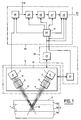
- FIG. 1 represents the entire system for determining the position of a plane separating two media of different densities, from measurements using the COMPTON effect.
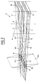
- FIG. 2 represents a collimator comprising a plurality of slots, according to the invention.
- an emitter E marked 1, consisting of a shielded and stabilized source, emits a beam 2 of X or ⁇ radiation through a first collimator 3 comprising a plurality of slots defining a very narrow incident beam 4 consisting of a plurality of elementary beams, penetrating through a front face serving as a reference plane 5, in adjacent media to be analyzed 6a, 6b, 6c, generally referenced 6, of different densities and separated according to a separation plane 7.
- the front face of one of the media serving as reference plane 5 is, in this example, assumed to be plane and parallel to plane 7; if this were not the case, any other surface or plane making it possible to serve as a fixed reference for the measurements of distances from the separation plane 7 would be suitable.
- a beam 8 of radiation scattered by the COMPTON effect reaches a second collimator 9 comprising a plurality of slots defining a solid acceptance angle for a detected beam 10 received by a receiver R , marked 11, located behind the second collimator 9.
- the two beams 4 and 10 are oriented in such a way that they intersect and define an elementary volume 12 that can occupy said media 6 and whose emission by COMPTON effect is received by receiver 11.
- the transmitter 1, the receiver 11 and the two collimators 3 and 9 are fixed on a common rigid support 13, the whole constituting a measurement assembly 14.
- the measurement assembly 14 is then moved with respect to the media 6 to be analyzed, or, conversely, these are moved so as to explore them at various depths and various locations under the front face 5.
- a computer 20 comprises a time base 21 governing the sequencing of successive measurement cycles, each relating to a given position of said elementary volume 12 in the media 6.
- This time base controls a relative displacement device 22 of the set of measurement 14 with respect to the media 6, by means of stepping motors 23 allowing at least to vary, by a certain number of elementary steps, the distance, with respect to an initial position, between the measuring assembly 14 and the reference plane 5, so as to carry out one of said successions of measurement cycles, and possibly to move this measurement assembly 14 in one or two (not shown) directions parallel to said reference plane 5, to perform d 'other successions of measurement cycles, relating to elementary volumes situated along another perpendicular to the reference plane 5.
- an integrator 24 At the output of the receiver 11 is an integrator 24, which can be located in the computer 20 or else near the receiver 11 to avoid receiving electrical noise, and receiving a first signal, representative of the number of photons received by the receiver 11 , and transmitted by the latter to this integrator 24, which is under the control of said time base 21.
- This integrator 24 provides, to a subtractor 25 from computer 20, controlled by time base 21, a second signal representative of the integral with respect to time of said first signal.
- This second signal is also applied to a first terminal B1, thus allowing the user to have said second signal which varies as the density of the medium 6 occupying the elementary volume 12 analyzed.
- This subtractor 25 stores said second signal and supplies therefrom a third signal representative of the difference between the second signal which has just been received and that received in the previous cycle.
- This third signal is applied to a first calculation means 26, controlled by the time base 21, which provides a fourth signal representative of the derivative of said third signal with respect to the distance to said reference plane 5, by dividing said third signal by the number of elementary steps from which the measuring assembly 14 has just moved at the start of the current cycle. This last division operation is obviously only necessary if the displacement of the measuring assembly 14 is likely to have different amplitudes from one cycle to the other.
- This fifth signal is applied to a third calculation means 28 of said computer 20, controlled by the time base 21 through a first input, and also receiving from this, on the second and third inputs, the commands of the movement device coming from this time base 21, respectively in the direction perpendicular to the reference plane 5 and one (or two) direction (s) parallel to this plane 5.
- This third calculation means 28 stores this fifth signal and supplies, on a terminal B2, when said fifth signal is zero or of opposite sign to that of the fifth signal generated in the previous cycle, a sixth signal representative of a displacement distance of the measuring assembly 14, with respect to its initial position at the start of the succession of cycles, distance which corresponds to the relative position of the barycenter of the successive distances relative to the last series of fifth non-zero successive signals calculated and of the same sign during the preceding cycles, each such fifth signal weighting by its value the distance of movement at which the measuring assembly 14 d was e its initial position, during the cycle in which this fifth signal was generated.
- this sixth signal is thus found to be representative in the same way of the position of the separation plane 7 of adjacent media of different densities.
- the source of X or ⁇ radiation is a stable source, regulated in radiation intensity, which makes it possible to validly compare results obtained at different times.
- the divergence of the beam 2 leaving the emitter 1 is reduced by passing through the collimator 3 comprising a plurality of slots fi (with i positive integer), represented in FIG. 2.
- Each of these has a depth P of approximately 200 mm according to the direction of propagation of the beam, and a section of length L of approximately 6 mm and of width l of 0.1 to 0.4 mm.
- Each slit fi is limited by metal walls which stop radiation, the wall Pl perpendicular to the direction of the width l being very thin.
- the relative scale between l , L , P is not respected.
- the divergence of the elementary beam fei (with i positive integer) of each slit fi, in the plane PL perpendicular to the length L is very small, due to the very low ratio between the width l and the depth P of the slit fi; the two extreme radii are each indicated by an axis marked DL.
- each elementary beam fei has a section of very small width, of the order of magnitude of the width l of the slit fi, while its length is much greater, of the order of the length L of the slit fi .
- the loss of intensity of the radiation corresponding to the difference between the incident beam 2 on the first collimator 3 and the beam 4 leaving it, is therefore mainly due to the rays absorbed by the two largest parallel walls P1, perpendicular to the direction along the width l of the slot fi.
- Each of these slots fi is oriented so that all of the elementary beams fei passing through said slots fi respectively converge on the same surface S1, parallel to the face of said collimator 3 from which the beam 4, of width lv , of value close to the width l of the slots fi, and of length Lv , of value close to the length L.
- the set of elementary beams fei crosses a first common volume Vc1, containing said surface S1.
- This volume Vc1 is found to have an elongated shape, of length determined by the length L of the slots.
- the second collimator 9 is made up identically to the first collimator 3 and the set 10 of elementary beams fei received, transmitted by each slit fi, defines a second volume Vc2 having a surface S2, homologous to S1 and cutting it or being neighbor.
- the two volumes Vc1 and Vc2 define a common volume which is the elementary volume 12 of approximately diamond-shaped section, of small size, and of length extending over the initial length of the incident beams 4 or received 10, determined by the length L of the fi slots.
- a detector At the input of the receiver 11, a detector, with an area substantially equal to the section of the received beam 10, transforms the photons received into an electrical signal constituting said first signal representative of the number of photons received.
- the first and the second collimator 3 and 9 are placed in such a way that the outlet section of each slot fi has its length L arranged parallel to the reference plane 5.
- all the points of said elementary volume 12 are located substantially at equal distance of this reference plane 5, merged with the front face of a medium 6, assumed to be parallel to the sought planes 7 separating the media of different densties. Therefore, all the points of this elementary volume 12 located at the same distance from the reference plane 5 are in material of the same density, and they emit identical signals that can be accumulated.
- the system works as follows.
- the measuring assembly 14 is placed in an initial position located at a determined distance from the media 6 to be analyzed, so that said elementary volume 12 can be moved and crosses the plane 7 separating said media 6, substantially perpendicular to the reference plane. 5.
- the computer 20 will then manage, by means of the time base 21, a succession of measurement and calculation cycles, each such cycle being linked to a determined relative displacement, relative to an initial position thus defined, of the measuring assembly 14 with respect to the reference plane 5, the relative displacement taking place in a direction substantially perpendicular to said reference plane 5 and therefore to the plane of separation 7 of the media 6.
- a succession of measurement and calculation cycles each such cycle being linked to a determined relative displacement, relative to an initial position thus defined, of the measuring assembly 14 with respect to the reference plane 5, the relative displacement taking place in a direction substantially perpendicular to said reference plane 5 and therefore to the plane of separation 7 of the media 6.
- the time base 21 first controls, by means of a first command, the relative displacement (advance in the example described), of the measuring assembly 14 with respect to the media 6, by the sending of an advance order to the stepping motor 23 controlling the movement in the direction perpendicular to the reference plane 5.
- the time base 21 commands the start of integration of the integrator 24, by sending to the latter a second command constituting an order to start integration; the first signal, coming from the receiver 11 is then integrated with respect to time.
- a third command, controlling the end of integration, is then transmitted by the time base 21 to said integrator 24 after a predetermined time, which stops the integration.
- the resulting integrated signal constitutes the second signal which is received by the subtractor 25.
- the time base 21 then issues a third command received by the subtractor 25, which, first of all, then stores said third signal in a random access memory. Said subtractor will then read the value in memory of the third signal which has just been received, as well as that of the third signal received in the preceding cycle, the latter being subtracted from the third signal which has just been received, for example in digital form , and the result is a fourth signal representing the derivative of said third signal with respect to the length of the movement ordered at the start of the cycle in progress. If the length of this displacement is likely to vary from one cycle to another, said third signal is then divided by said displacement length at the start of the cycle in progress, which in this case provides said fourth signal representative of the derivative said third signal with respect to the length measured in the direction of travel.
- the time base 21 then emits a fourth command received by the second calculation means 27 which, from the fourth signal, supplies a fifth signal, as explained above, corresponding to the excess of the fourth signal with respect to said number predetermined positive and which constitutes a threshold.
- the time base 21 then transmits a fifth command to the third calculation means 28, which then stores said fifth signal then optionally performs the barycenter calculation, as explained above, and then provides said sixth signal on terminal B2 , representative of the position relative to a plane 7 separating two media of different densities, expressed as the value of the relative displacement of the measuring assembly 14 with respect to the media 6 in the direction perpendicular to the plane of separation 7 of the media.
- the third calculation means 28 can translate the displacement of the measuring assembly 14 relative to its initial position into a displacement relative to the reference plane 5, taken, for example , as being the front face of a medium 6, insofar as it is plane and parallel to the separation planes 7.
- the initial position of the elementary volume 12 can also serve as a reference, its distance from the measuring assembly 14 being fixed and known by triangulation of the two beams 4 and 10.
- Another method consists in passing the elementary volume 12 through the front face of the medium 6, which brings a precision equal to the subsequent determinations of positions of separation planes 7 and thus avoids errors in measuring the distance between the set of measure 14 and the reference plane 5 consisting of the front face of a medium 6.
- the succession of determinations of the positions of the various planes of separation 7 of the media makes it possible, by calculating the difference of the relative positions of the said planes of separation 7, to deduce the thickness of each of the media and its precise position.
Landscapes
- Physics & Mathematics (AREA)
- Chemical & Material Sciences (AREA)
- General Physics & Mathematics (AREA)
- Life Sciences & Earth Sciences (AREA)
- Crystallography & Structural Chemistry (AREA)
- Health & Medical Sciences (AREA)
- Electromagnetism (AREA)
- Analytical Chemistry (AREA)
- Biochemistry (AREA)
- General Health & Medical Sciences (AREA)
- Immunology (AREA)
- Pathology (AREA)
- Measurement Of Radiation (AREA)
- Analysing Materials By The Use Of Radiation (AREA)
- Length-Measuring Devices Using Wave Or Particle Radiation (AREA)
Claims (6)
- System zur Lokalisierung der Trennungsebene (7) zwischen zwei Medien (6) unterschiedlicher Dichte gegenüber einer parallel zur Trennungsebene (7) und in einem unveränderlichen Abstand zu dieser verlaufenden Referenzebene (5), wobei die Medien von einem Röntgen- oder Gammastrahlenbündel (2) aus einem Strahler (1) bestrahlt werden können, an dessen Ausgang sich ein erster Kollimator (3) befindet und der eine Compton-Effekt-Streuung erzeugt, die durch einen Empfänger (11) erfaßt wird, der als Reaktion ein erstes Signal abgibt und an dessen Eingang sich ein zweiter Kollimator (9) befindet, wobei sich der Empfänger (11) auf einer Unterlage (13) befindet, die durch eine Verschiebungsvorrichtung (22) bewegt wird, und das System eine Verarbeitungsvorrichtung des ersten Signals umfaßt,
dadurch gekennzeichnet, daß:- die Intensität des Strahlers geregelt ist;- eine Zeitbasis (21) Ablaufbefehle für Verschiebungs-, Meß- und Rechenfolgezyklen abgibt, wobei eine solche Zyklusfolge Messungen einer Folge von Untersuchungsvolumen, die nach einer annähernd senkrecht zur Referenzebene (5) verlaufenden Linie gestaffelt sind, entspricht;- die Verschiebungsvorrichtung (22) durch die Zeitbasis (21) gesteuert wird und die relative Verschiebung der Unterlage (13) gegenüber der Referenzebene (5) annähernd senkrecht zu dieser kontrolliert;- der erste Kollimator (3) wenigstens einen Spalt (fi) hat, auf der Unterlage (13) befestigt ist und sein durch den Spalt (fi) gelangendes Elementarbündel (fei) auf ein Elementarvolumen (12) von länglicher Form parallel zur gesuchten Trennungsebene (7) zwischen den Medien (6), das von den Medien (6) eingenommen werden kann, gerichtet ist;- der zweite Kollimator (9) eine Vielzahl von Spalten (fi) hat und seine durch die Spalte (fi) gelangenden Elementarbündel (fei) zum Elementarvolumen (12) konvergieren;- die Unterlage (13), der Strahler (1), der erste (3) und der zweite (9) Kollimator und der Empfänger (11) eine Meßeinheit (14) bilden, deren relative Lage gegenüber der Referenzebene (5) mit der der Unterlage (13) identisch ist;- ein Zeitintegrator (24), der von der Zeitbasis (21) gesteuert wird, das erste Signal erhält und ein zweites Signal abgibt, das für das Zeitintegral des ersten Signals während einer von der Zeitbasis (21) definierten Zeit repräsentativ ist;- ein Subtrahierer (25), der von der Zeitbasis (21) gesteuert wird, das zweite Signal erhält und als Reaktion ein drittes Signal abgibt, das für die Differenz zwischen dem zweiten Signal des laufenden Zyklus und dem zweiten Signal des vorangegangenen Zyklus repräsentativ ist;- ein erstes Rechenmittel (26), das von der Zeitbasis (21) gesteuert wird, das dritte Signal erhält und als Reaktion ein viertes Signal abgibt, das für die Ableitung des dritten Signals bezogen auf den relativen Verschiebungsweg zwischen der Meßeinheit (14) und der Referenzebene (5) repräsentativ ist;- ein zweites Rechenmittel (27), das von der Zeitbasis (21) gesteuert wird, das vierte Signal erhält und als Reaktion ein fünftes Signal abgibt, das für eine Zahl, deren absoluter Wert- entweder gleich der Differenz ist, die sich bei Abzug einer vorbestimmten positiven Zahl vom vierten Signal ergibt, wenn dieses Ergebnis positiv ist,- oder gleich Null ist, wenn dieses Ergebnis negativ oder Null ist,
und mit einem Vorzeichen gleich dem des vierten Signals repräsentativ ist;- ein drittes Rechenmittel (28), das von der Zeitbasis (21) gesteuert wird, an einem ersten Eingang das fünfte Signal und an einem zweiten Eingang den Befehl der Zeitbasis (21) zur relativen Verschiebung der Unterlage (13) gegenüber der Referenzebene (5) annähernd senkrecht zu dieser erhält, das fünfte Signal speichert und, wenn das fünfte Signal Null ist oder ein dem fünften Signal des vorangegangenen Zyklus entgegengesetztes Vorzeichen hat, ein sechstes Signal erzeugt, das für einen Verschiebungsweg der Meßeinheit (14) gegenüber ihrer Ausgangslage zu Beginn der Zyklusfolge repräsentativ ist, wobei der Verschiebungsweg der relativen Lage des Schwerpunkts der aufeinanderfolgenden Wege für die letzte Folge fünfter Signale ungleich Null mit gleichem Vorzeichen entspricht, die in den vorangegangenen Zyklen berechnet wurden, jedes fünfte Signal einer solchen Folge mit seinem Wert den Verschiebungsweg wichtet, den die Meßeinheit (14) aus ihrer Ausgangslage während des Zyklus genommen hat, in dem dieses fünfte Signal erzeugt wurde, und sich der Schwerpunkt in einer Trennungsebene (7) zwischen zwei aneinandergrenzenden Medien (6) befindet. - System nach Anspruch 1,
dadurch gekennzeichnet, daß der erste Kollimator (3) eine Vielzahl von Spalten hat, und dadurch, daß die durch die Spalten hindurchtretenden Elementarbündel nach dem Elementarvolumen (12) konvergieren. - System nach einem der Ansprüche 1 oder 2,
dadurch gekennzeichnet, daß es eine Vorrichtung (22) zur relativen Verschiebung der Meßeinheit (14) gegenüber Medien (6) in einer Richtung parallel zur Referenzebene (5) umfaßt: - System nach einem der Ansprüche 1 bis 3,
dadurch gekennzeichnet, daß alle Elementarbündel (fei) (mit i = 1, 2, 3 usw.), die jeweils durch einen der Spalte (fi) übertragen werden, zu einem gemeinsamen Volumen (Vc1, Vc2) konvergieren, dessen eine Abmessung zwischen 0,1 mm und 0,4 mm liegt. - Verfahren zur Lokalisierung der Trennungsebene (7) zwischen zwei Medien (6) unterschiedlicher Dichte gegenüber einer parallel und in unveränderlichem Abstand zur Trennungsebene (7) verlaufenden Referenzebene (5), wobei die Medien (6) von einem Röntgen- oder Gammastrahlenbündel (2) aus einem Strahler (1) unter Erzeugung einer Compton-Effekt-Streuung bestrahlt werden können, die von einem Empfänger (11) erfaßt wird, der als Reaktion ein erstes Signal abgibt, wobei sich der Empfänger (11) auf einer Unterlage (13) befindet, die von einer Verschiebungsvorrichtung (22) bewegt wird, das erste Signal von einer Verarbeitungsvorrichtung verarbeitet und das Röntgen- oder Gammastrahlenbündel (3) sowie die Compton-Effekt-Strahlung räumlich gefiltert werden,
dadurch gekennzeichnet, daß es aus einer Folge von Zyklen besteht, die Messungen einer Folge von Untersuchungsvolumen entsprechen, die nach einer annähernd senkrecht zur Referenzebene (5) verlaufenden Linie gestaffelt sind, wobei jeder Zyklus folgende Stufen umfaßt:- Steuerung einer Vorrichtung (22) zur kontrollierten relativen Verschiebung der Unterlage (13) gegenüber der Referenzebene (5), annähernd senkrecht zu derselben;- durch einen Strahler (1) auf der Unterlage (13) Abgabe eines Röntgen- oder Gammastrahlenbündels (2) mit geregelter Intensität;- räumliche Filterung des Bündels (2) durch einen ersten Kollimator (3) mit wenigstens einem Spalt (fi), der auf der Unterlage (13) befestigt ist und dessen durch den Spalt (fi) hindurchtretendes Elementarbündel (fei) auf ein Elementarvolumen (12) von länglicher Form gerichtet ist, das parallel zur gesuchten Trennungsebene (7) zwischen den Medien (6) verläuft und von den Medien (6) eingenommen werden kann, wobei sich der erste Kollimator (3) am Ausgang des Strahlers (1) befindet;- räumliche Filterung der vom Elementarvolumen (12) abgegebenen Compton-Effekt-Strahlung durch einen zweiten Kollimator (9) mit einer Vielzahl von Spalten (fe), der auf der Unterlage (13) befestigt ist, dessen durch die Spalten (fi) gelangende Elementarbündel (fei) nach dem Elementarvolumen (12) konvergieren und der sich vor dem Detektor von Empfänger (11) befindet, wobei die Unterlage (13), der Strahler (1), der erste (3) und der zweite (9) Kollimator und der Empfänger (11) eine Meßeinheit (14) bilden, deren relative Lage gegenüber der Referenzebene (5) mit der der Unterlage (13) identisch ist;- Zeitintegration des ersten Signals in einem Zeitintegrator (24), der von der Zeitbasis (21) gesteuert wird, das erste Signal erhält und ein zweites Signal abgibt, das für das Zeitintegral des ersten Signals während einer von der Zeitbasis (21) definierten Zeit repräsentativ ist;- in einem von der Zeitbasis (21) gesteuerten Subtrahierer (25), an den das zweite Signal gelangt, Subtraktion des zweiten Signals des vorangegangenen Zyklus vom zweiten Signal des laufenden Zyklus, so daß sich ein drittes Signal ergibt;- in einem ersten Rechenmittel (26), das von der Zeitbasis (21) gesteuert wird und an das das dritte Signal gelangt, Ableitung des dritten Signals nach dem relativen Verschiebungsweg zwischen der Meßeinheit (14) und der Referenzebene (5), so daß sich ein viertes Signal ergibt;- in einem zweiten Rechenmittel (27), das von der Zeitbasis (21) gesteuert wird und an das das vierte Signal gelangt, Berechnung einer Zahl, deren absoluter Wert- entweder gleich der Differenz ist, die sich bei Abzug einer vorbestimmten positiven Zahl vom vierten Signal ergibt, wenn dieses Ergebnis positiv ist,- oder gleich Null ist, wenn dieses Ergebnis negativ oder Null ist,
und mit einem Vorzeichen gleich dem des vierten Signals, wobei die Zahl ein fünftes Signal darstellt;- in einem dritten Rechenmittel (28), das von der Zeitbasis (21) gesteuert wird, an das an einem ersten Eingang das fünfte Signal und an einem zweiten Eingang der Befehl der Zeitbasis (21) für die relative annähernd senkrechte Verschiebung der Unterlage (13) gegenüber der Referenzebene (5) gelangt und das dieses fünfte Signal speichert, Berechnung eines sechsten Signals, wenn das fünfte Signal Null ist oder ein Vorzeichen entgegengesetzt dem des im vorangegangenen Zyklus erzeugten fünften Signals hat, wobei das sechste Signal für einen Verschiebungsweg der Meßeinheit (14) gegenüber ihrer Ausgangslage zu Beginn der Zyklusfolge repräsentativ ist, der Verschiebungsweg der relativen Lage des Schwerpunkts der aufeinanderfolgenden Verschiebungswege für die letzte Folge fünfter Signale ungleich Null mit gleichem Vorzeichen, die in den vorangegangenen Zyklen berechnet wurden, entspricht, jedes derartige fünfte Signal einer solchen Folge durch seinen Wert den Verschiebungsweg wichtet, den die Meßeinheit (14) während des Zyklus, in dem dieses fünfte Signal erzeugt wurde, aus ihrer Ausgangslage zurückgelegt hat, und der Schwerpunkt in einer Trennungsebene (7) zwischen zwei aneinandergrenzenden Medien (6) liegt. - Verfahren nach Anspruch 5,
dadurch gekennzeichnet, daß ein erster Kollimator (3) mit einer Vielzahl von Spalten für eine Vielzahl von Elementarbündeln verwendet wird, die nach dem Elementarvolumen (12) konvergieren.
Applications Claiming Priority (2)
| Application Number | Priority Date | Filing Date | Title |
|---|---|---|---|
| FR9101051A FR2672120B1 (fr) | 1991-01-30 | 1991-01-30 | Procede et systeme a effet compton pour la localisation d'un plan separant deux milieux de densites differentes. |
| FR9101051 | 1991-01-30 |
Publications (2)
| Publication Number | Publication Date |
|---|---|
| EP0498687A1 EP0498687A1 (de) | 1992-08-12 |
| EP0498687B1 true EP0498687B1 (de) | 1995-03-01 |
Family
ID=9409201
Family Applications (1)
| Application Number | Title | Priority Date | Filing Date |
|---|---|---|---|
| EP92400173A Expired - Lifetime EP0498687B1 (de) | 1991-01-30 | 1992-01-22 | Verfahren und System mit Verwendung des Compton Effektes zur Ortung der Trennungsebene zwischen zwei Medien unterschiedlicher Dichte |
Country Status (6)
| Country | Link |
|---|---|
| US (1) | US5195116A (de) |
| EP (1) | EP0498687B1 (de) |
| JP (1) | JPH04318411A (de) |
| CA (1) | CA2060265A1 (de) |
| DE (1) | DE69201497T2 (de) |
| FR (1) | FR2672120B1 (de) |
Families Citing this family (10)
| Publication number | Priority date | Publication date | Assignee | Title |
|---|---|---|---|---|
| DK171492B1 (da) * | 1994-06-20 | 1996-11-25 | Wesser & Dueholm | Fremgangsmåde til bestemmelse af densitetsprofil i et pladeformet materiale |
| US5666394A (en) * | 1996-04-23 | 1997-09-09 | Northrop Grumman Corporation | Thickness measurement gauge |
| SE513401C2 (sv) * | 1999-01-15 | 2000-09-11 | Volvo Aero Corp | Förfarande och anordning för att bestämma läget av ett långsträckt föremål i förhållande till ytan på en framförliggande kropp med hjälp av elektromagnetisk strålning |
| FI990153A0 (fi) * | 1999-01-28 | 1999-01-28 | Valtion Teknillinen | Tiheysjakaumaltaan homogeenisen materiaalin/puuhakkeen kosteuden on-line mittausmenetelmä perustuen gammasäteilyn transmissioon ja materiaaliin paksuuden mittaukseen |
| RU2180439C2 (ru) * | 2000-02-11 | 2002-03-10 | Кумахов Мурадин Абубекирович | Способ получения изображения внутренней структуры объекта с использованием рентгеновского излучения и устройство для его осуществления |
| US6421418B1 (en) | 2000-08-15 | 2002-07-16 | Northrop Grumman Corporation | Method and system for detecting hidden edges |
| EP1258723A1 (de) * | 2001-05-18 | 2002-11-20 | Imal S.R.L. | Nichtzerstörendes Verfahren zum kontinuierlischen Messen des Dichteprofils von Platten |
| RU2242776C2 (ru) * | 2002-12-11 | 2004-12-20 | Закрытое акционерное общество "Оптик" | Дифракционная решетка и способ ее изготовления |
| NZ538649A (en) | 2005-03-07 | 2006-10-27 | Inst Geolog Nuclear Sciences | Estimating strengths of wooden supports using gamma rays |
| ITMO20050341A1 (it) * | 2005-12-23 | 2007-06-24 | Imal Srl | Apparecchiatura per la misura di densita' di manufatti, particolarmente di pannelli in materiale incoerente pressato, e metodo relativo |
Citations (1)
| Publication number | Priority date | Publication date | Assignee | Title |
|---|---|---|---|---|
| EP0011897A1 (de) * | 1978-11-27 | 1980-06-11 | Laboratoires D'electronique Et De Physique Appliquee L.E.P. | Einrichtung zur tomographischen Abtastung eines Körpers mittels Röntgen- oder Gamma-Strahlen |
Family Cites Families (3)
| Publication number | Priority date | Publication date | Assignee | Title |
|---|---|---|---|---|
| US4165460A (en) * | 1977-11-04 | 1979-08-21 | Nasa | Coal-rock interface detector |
| JPS57197410A (en) * | 1981-05-29 | 1982-12-03 | Rigaku Denki Kogyo Kk | Measuring method of adhered amount of high polymer film on metallic plate |
| US5029337A (en) * | 1989-01-19 | 1991-07-02 | Tava Corporation | Method for measuring coating thickness |
-
1991
- 1991-01-30 FR FR9101051A patent/FR2672120B1/fr not_active Expired - Fee Related
-
1992
- 1992-01-22 DE DE69201497T patent/DE69201497T2/de not_active Expired - Fee Related
- 1992-01-22 US US07/823,818 patent/US5195116A/en not_active Expired - Fee Related
- 1992-01-22 EP EP92400173A patent/EP0498687B1/de not_active Expired - Lifetime
- 1992-01-29 CA CA002060265A patent/CA2060265A1/fr not_active Abandoned
- 1992-01-30 JP JP4015298A patent/JPH04318411A/ja active Pending
Patent Citations (1)
| Publication number | Priority date | Publication date | Assignee | Title |
|---|---|---|---|---|
| EP0011897A1 (de) * | 1978-11-27 | 1980-06-11 | Laboratoires D'electronique Et De Physique Appliquee L.E.P. | Einrichtung zur tomographischen Abtastung eines Körpers mittels Röntgen- oder Gamma-Strahlen |
Also Published As
| Publication number | Publication date |
|---|---|
| FR2672120A1 (fr) | 1992-07-31 |
| DE69201497T2 (de) | 1995-07-20 |
| FR2672120B1 (fr) | 1993-05-14 |
| EP0498687A1 (de) | 1992-08-12 |
| CA2060265A1 (fr) | 1992-07-31 |
| JPH04318411A (ja) | 1992-11-10 |
| US5195116A (en) | 1993-03-16 |
| DE69201497D1 (de) | 1995-04-06 |
Similar Documents
| Publication | Publication Date | Title |
|---|---|---|
| EP0701703B1 (de) | Verfahren und vorrichtung zur erkennung von bestimmten materialien in der zusammensetzung eines gegenstands | |
| EP3701222B1 (de) | Verfahren und vorrichtung zur messung von abmessungen durch röntgenstrahlen auf in einer linie verlaufenden leeren glasbehältern | |
| EP3701221B1 (de) | Verfahren und einrichtung zur inline-dimensionssteuerung von hergestellten gegenständen | |
| EP0498687B1 (de) | Verfahren und System mit Verwendung des Compton Effektes zur Ortung der Trennungsebene zwischen zwei Medien unterschiedlicher Dichte | |
| EP0485265B1 (de) | Verfahren und Methode zur zerstörungsfreien Prüfung mit gleichzeitiger Aufnahme von Röntgendaten und tomographischen Daten | |
| FR2664042A1 (fr) | Controleur de dimension de spot pour un appareil de prise de vues a profondeur de champ variable. | |
| EP0622610A1 (de) | Verfahren und Anordnung zum Eichen der Dickenmessanordnung des Querprofils eines flächigen Gutes | |
| RU2119660C1 (ru) | Устройство для определения состава и структуры неоднородного объекта (варианты) | |
| EP0337831B1 (de) | Verfahren und Vorrichtung zur Bestimmung der Dichte eines Materien-Volumenelements | |
| JP2005140777A (ja) | サンプル検査方法、その装置、マイクロエレクトロニクス装置製造用クラスタツール、マイクロエレクトロニクス装置製造用装置 | |
| EP1733205B1 (de) | Verfahren und system zur bestimmung von massedichte und abmessungsmerkmalen eines gegenstands sowie dessen verwendung zur überwachung von kernbrennstoffpellets während deren herstellung | |
| CA2163884C (fr) | Procede et dispositif pour la reconnaissance de materiaux determines dans la composition d'un objet | |
| EP4010739A1 (de) | Rotierender kollimator für ein röntgendetektionssystem | |
| EP3629063B1 (de) | Spektrometriesystem, entsprechendes spektrometrieverfahren und computerprogrammprodukt | |
| CA3172062C (en) | Method and system for inspecting a structure across a cover layer covering the structure | |
| FR2993674A1 (fr) | Procede de mesure de l'activite d'une source d'emission de photons | |
| EP3517940B1 (de) | Verfahren und system zur bestimmung der variation der streuintensität eines zweidimensionalen gitters entlang einer bestimmten richtung | |
| EP2368140B1 (de) | Verfahren zur bestimmung der spektralen und räumlichen verteilung von bremsphotonen und diesbezügliche einrichtung | |
| FR2631121A1 (fr) | Dispositif de controle du taux de dissolution d'un residu nucleaire dans une solution de dissolveur | |
| FR2586484A1 (fr) | Appareil de diagraphie de densite de formations souterraines utilisant deux detecteurs et sources | |
| JP2594220B2 (ja) | 蛍光x線分析方法 | |
| EP2449533B1 (de) | Röntgenbildgebungsverfahren und vorrichtung mit dreidimensionaler verarbeitung | |
| FR2587804A1 (fr) | Systeme de controle au defile, de pieces, par un rayonnement penetrant | |
| Lammers | Light Collection and Scatter Corrections in the EUT РЕР detector | |
| FR2683899A1 (fr) | Procede et dispositif de mesure de la largeur d'une bande mince en defilement continu. |
Legal Events
| Date | Code | Title | Description |
|---|---|---|---|
| PUAI | Public reference made under article 153(3) epc to a published international application that has entered the european phase |
Free format text: ORIGINAL CODE: 0009012 |
|
| AK | Designated contracting states |
Kind code of ref document: A1 Designated state(s): BE DE GB IT |
|
| 17P | Request for examination filed |
Effective date: 19920921 |
|
| 17Q | First examination report despatched |
Effective date: 19931105 |
|
| GRAA | (expected) grant |
Free format text: ORIGINAL CODE: 0009210 |
|
| AK | Designated contracting states |
Kind code of ref document: B1 Designated state(s): BE DE GB IT |
|
| GBT | Gb: translation of ep patent filed (gb section 77(6)(a)/1977) |
Effective date: 19950227 |
|
| REF | Corresponds to: |
Ref document number: 69201497 Country of ref document: DE Date of ref document: 19950406 |
|
| ITF | It: translation for a ep patent filed | ||
| PLBE | No opposition filed within time limit |
Free format text: ORIGINAL CODE: 0009261 |
|
| STAA | Information on the status of an ep patent application or granted ep patent |
Free format text: STATUS: NO OPPOSITION FILED WITHIN TIME LIMIT |
|
| 26N | No opposition filed | ||
| PGFP | Annual fee paid to national office [announced via postgrant information from national office to epo] |
Ref country code: DE Payment date: 20001229 Year of fee payment: 10 |
|
| PGFP | Annual fee paid to national office [announced via postgrant information from national office to epo] |
Ref country code: BE Payment date: 20010110 Year of fee payment: 10 |
|
| PGFP | Annual fee paid to national office [announced via postgrant information from national office to epo] |
Ref country code: GB Payment date: 20010118 Year of fee payment: 10 |
|
| REG | Reference to a national code |
Ref country code: GB Ref legal event code: IF02 |
|
| PG25 | Lapsed in a contracting state [announced via postgrant information from national office to epo] |
Ref country code: GB Free format text: LAPSE BECAUSE OF NON-PAYMENT OF DUE FEES Effective date: 20020122 |
|
| PG25 | Lapsed in a contracting state [announced via postgrant information from national office to epo] |
Ref country code: BE Free format text: LAPSE BECAUSE OF NON-PAYMENT OF DUE FEES Effective date: 20020131 |
|
| BERE | Be: lapsed |
Owner name: AEROSPATIALE SOC. NATIONALE INDUSTRIELLE Effective date: 20020131 |
|
| PG25 | Lapsed in a contracting state [announced via postgrant information from national office to epo] |
Ref country code: DE Free format text: LAPSE BECAUSE OF NON-PAYMENT OF DUE FEES Effective date: 20020801 |
|
| GBPC | Gb: european patent ceased through non-payment of renewal fee |
Effective date: 20020122 |
|
| PG25 | Lapsed in a contracting state [announced via postgrant information from national office to epo] |
Ref country code: IT Free format text: LAPSE BECAUSE OF NON-PAYMENT OF DUE FEES;WARNING: LAPSES OF ITALIAN PATENTS WITH EFFECTIVE DATE BEFORE 2007 MAY HAVE OCCURRED AT ANY TIME BEFORE 2007. THE CORRECT EFFECTIVE DATE MAY BE DIFFERENT FROM THE ONE RECORDED. Effective date: 20050122 |