EP0498986A2 - Automatischer Schirm mit einem in gerader Linie zu bewegenden Druckknopf zum Öffnen und Schliessen des Schirmes - Google Patents
Automatischer Schirm mit einem in gerader Linie zu bewegenden Druckknopf zum Öffnen und Schliessen des Schirmes Download PDFInfo
- Publication number
- EP0498986A2 EP0498986A2 EP91309505A EP91309505A EP0498986A2 EP 0498986 A2 EP0498986 A2 EP 0498986A2 EP 91309505 A EP91309505 A EP 91309505A EP 91309505 A EP91309505 A EP 91309505A EP 0498986 A2 EP0498986 A2 EP 0498986A2
- Authority
- EP
- European Patent Office
- Prior art keywords
- shaft
- umbrella
- controller
- closing
- push button
- Prior art date
- Legal status (The legal status is an assumption and is not a legal conclusion. Google has not performed a legal analysis and makes no representation as to the accuracy of the status listed.)
- Granted
Links
- 230000000994 depressogenic effect Effects 0.000 claims abstract description 7
- 230000000717 retained effect Effects 0.000 claims abstract description 7
- 230000000979 retarding effect Effects 0.000 claims description 15
- 239000004744 fabric Substances 0.000 claims description 2
- 230000000881 depressing effect Effects 0.000 abstract description 8
- 230000008878 coupling Effects 0.000 description 3
- 238000010168 coupling process Methods 0.000 description 3
- 238000005859 coupling reaction Methods 0.000 description 3
- 240000007643 Phytolacca americana Species 0.000 description 1
- 230000006835 compression Effects 0.000 description 1
- 238000007906 compression Methods 0.000 description 1
Images


Classifications
-
- A—HUMAN NECESSITIES
- A45—HAND OR TRAVELLING ARTICLES
- A45B—WALKING STICKS; UMBRELLAS; LADIES' OR LIKE FANS
- A45B25/00—Details of umbrellas
- A45B25/14—Devices for opening and for closing umbrellas
- A45B25/143—Devices for opening and for closing umbrellas automatic
Definitions
- the present invention relates to an automatic umbrella.
- U.S. Patent No. 4,941,494 was invented by the inventor named in the present application and was entitled "Lightly-operating Automatic Umbrella for Preventing False Operation".
- U.S. Patent No. 4,941,494 discloses a seesaw button 51 for operatively depressing an extension controller 52 for opening the umbrella or operatively depressing a retraction controller 53 for closing the umbrella.
- the push button 51 of the control means 5 By operating the push button 51 of the control means 5, the umbrella may be conveniently opened or closed.
- this is still an operating inconvenience when opening or closing the umbrella, particularly in dark weather or at night.
- the present invention recognises the disadvantages of the prior art patent and is intended to overcome these disadvantages by providing an automatic umbrella which can be opened or closed by simply depressing a push button of the umbrella.
- an automatic umbrella having a straightforward push button resiliently held in a grip of the umbrella, an opening controller normally locking a shaft of the umbrella at a folded state and operatively actuated by depressing the push button for opening the umbrella, and a closing controller normally retarding a closing movement of an opened umbrella and operatively actuated by depressing the push button for closing the umbrella, in that the operation for opening or closing the umbrella is effected by merely depressing the push button straightforwardly, other than a selective depression on an upper portion or a lower portion of the button, for a convenient opening or closing operation of the umbrella.
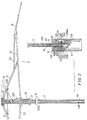
- the present invention comprises: a central shaft means 1, a rib assembly 2 for securing an umbrella cloth thereon, an extending spring 3 for opening the umbrella, at least a retraction restoring spring 4 for closing the umbrella, and a control means 5 for the control of opening or closing operation of the umbrella.
- the central shaft means 1 includes: a lower tubular shaft 11, a grip 12, a sleeve 13 fixed in the lower shaft 11, an upper tubular shaft 14 telescopically mounted on the lower shaft 11, and an upper notch 15 formed on a top portion of the upper shaft 14 having an inner block 16 fixed therein.
- the lower tubular shaft 11 has its lower portion inserted in a central shaft hole 120 in the grip 12.
- the sleeve 13 includes an upper taper opening 131 for smoothly guiding a locking head 536 of the closing controller 53 of the control means 5 into the sleeve 13.
- the upper tubular shaft 14 is formed with a lower hole 141 in a lower portion of the shaft 14.
- the rib assembly 2 is conventional as found in a conventional umbrella and may include: a first top rib 21 having an inner end portion of the rib 21 pivotally secured to the notch 15, a stretcher rib 22 having an inner end portion of the rib 22 pivotally secured to a runner 25 slidably encompassed on the upper tubular shaft 14 and having a middle portion of the rib 22 pivotally secured with an outermost end portion of the first rib 21, a second top rib 23 having its inner end portion pivotally secured to a second outer end portion of the first rib next to an outermost end portion of the first rib, and a third top rib 24 respectively pivotally secured to two outermost end portions of both second top rib 23 and stretcher rib 22.
- the extending spring 3 is an elongate coil spring having a diameter of each spring ring generally equal to an inside diameter of the lower shaft 11 having its lower end 31 retained on a top end of the sleeve 13 and having its upper end 32 retained against a bottom portion of the inner block 16 secured to the upper notch 15.
- the retraction restoring spring 4 normally urges the rib assembly 2 towards a collapsed state, such as for normally urging the strether rib 22 and runner 25 downwardly as shown in Figure 3 so as to close the umbrella.
- the elastic force of the spring 4 when compressed by extending the rib assembly 2 when opening the umbrella as shown in Figure 2, should always be smaller than the elastic force of the extending spring means 3 under compression when the umbrella is closed and the tubular shafts are shortened to accumulate the elastic force of the spring 3 as shown in Figure 1.
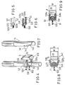
- the control means 5 includes: a straightforward push button 51, an opening controller 52 for controlling the extension of upper shaft 14 and the opening of the umbrella, and a closing controller 53 for the control of the retraction of the rib assembly 2 and the closing of the umbrella.
- the push button 51 is resiliently held in a button hole 121 formed in a side portion of the grip 12, having an upper portion 511 contacting the opening controller 52, a lower portion 512 operatively contacting the closing controller 53, and an inner base extension 513 resiliently retained in a side wall of the grip 12.
- the opening controller 52 includes: a pair of bifurcate arm members 521 laterally held in an upper slot 122 formed in an upper portion of the grip 12 slidably disposed around a lower portion of the upper shaft 14, a latch portion 522 formed in a central portion of the controller 52 between the two arm members 521 having an outer portion 522a tapered downwardly and having a length shorter than that of the arm member 521, and an upper tensioning spring 523 held in an upper portion of the grip 12 resiliently urging the latch portion 522 outwardly to engage the lower hole 141 of the upper shaft 14 when folding the umbrella as shown in Figure 10 and resiliently urging the two arm members 521 outwardly to contact the upper portion 511 of the push button 51.
- the closing controller 53 includes: a pair of bifurcate short stems 531 formed on two opposite sides of the controller 53 slidably disposed around said lower shaft 11 each stem 531 jacketed with a helical spring 531a thereon, a lower tensioning spring 532 formed in a lower portion of the grip 12 below the upper spring 523 normally urging the stems 531 and the helical springs 531a outwardly to contact the lower portion 512 of the push button 51, a retarding plate 533 formed on a central portion of the controller 53 between the two stems 531 having an arcuate surface 533a formed on an outer portion of the retarding plate 533, a drag rod 535 slidably held in the shaft means 1 having a lower locking head 536 secured to the rod 535 having a diameter of the head 536 larger than that of the rod 535 and a taper portion 536a formed on a lowest end portion of the head 536, and a flexible rope 537 (or wire) trailed inside the shaft means 1 or outside a
- the drag rod 535 has a length generally equal to a length of a shortened folded shaft means 1 as shown in Figure 1 having its lower locking head 536 normally locked by the retarding plate 533 and having its upper end portion secured with the coupling 538 limited by the inner block 16 secured on the upper portion of the upper shaft 14.
- the flexible rope 537 has a length generally equal to a length between the runner 25 when closing the umbrella and retracting the ribs 2 inwardly towards the shaft 1, and the inner block 16, against which block 16 the coupling 538 is retained as shown in Figure 3.
- a total length of the length of the upper rope 537 plus the length of the lower rod 535 is generally equal to a length of an extended shaft means 1 as shown in Figure 2.
- the straightforward push button 51 is straightforwardly depressed as shown in Figure 11 to press the latch portion 522 inwardly to disengage the hole 141 of the upper shaft 14 and the extending spring 3 will urge the inner block 16 and the upper shaft 14 upwardly so as to extend the ribs 2 outwardly upwardly for opening the umbrella as shown in Figure 2.
- the rope 537 and rod 535 having the locking head 536 locked by the closing controller 53 are linearly linked to counteract a retraction force urged by the restoring spring 4 for preventing a closing of umbrella then extended as shown in Figure 2.
- a lower portion of the upper shaft 14 is formed with a recess portion 142 under the lower hole 141 and a lower flange 143 protruding downwardly from the recess portion 142 to be lower than the position of the bifurcate stems 531 and helical springs 531a of the closing controller 53 when folding the umbrella by engaging the latch portion 522 of the opening controller 52 with the lower hole 141 of the upper shaft 14.
- the lower flange 143 of the upper shaft 14 slidably held on the lower shaft 11 will bias the two helical springs 531a sidewardly as shown in Figure 8 to form an aperture D between the two separated springs 531a, which aperture D is greater than a width W of the push button 51 so that during the depression of the push button 51 to open the umbrella as shown in Figure 11 from Figure 10, the inward movement of the button 51 will not depress the two springs 531a in view of Figure 8, thereby without falsely actuating the closing controller 53 and thereby still locking the locking head 536 by the retarding plate 533 of the closing controller.
- Figure 12 shows a fully opened umbrella grip 12 and controller 5.
- the button 51 is depressed from Figure 12 to Figure 13 to press the two helical springs 531a and the retarding plate 533 inwardly to release the locking head 536.
- the restoring spring 4 normally urges the stretcher rib 22 and runner 25 downwardly to retract the rib assembly 2 towards the central shaft means 1 to pull the rope 537 outwardly through the roller 539 to raise the rod 535 upwardly until being limited by the block 16 since the rod 535 and locking head 536 is no longer locked by the retarding plate 533, thereby closing the umbrella automatically as shown in Figure 3.
- the recess portion 142 of the upper shaft 14 will first meet the tapered outer portion 522a of the latch portion 522 to depress the latch portion 522 inwardly to poke the lower portion of the shaft 14 into a socket 122a of the grip 12 until engaging the latch portion 522 with the hole 141 of the shaft 14 to stably fold the umbrella.
- the recess portion 142 should be positioned above the retarding plate 533 of the closing controller 53 to prevent any obstruction of the operation of the controller 53.
- the present invention is superior to the inventor's earlier patented U.S. Patent 4,941,494 because the straightforward push button 51 of this invention can be depressed straightforwardly without carefully selecting an upper portion or a lower portion of the button 51 as disclosed in such a U. S. patent 4,941,494.
Landscapes
- Walking Sticks, Umbrellas, And Fans (AREA)
- Holders For Apparel And Elements Relating To Apparel (AREA)
Applications Claiming Priority (2)
| Application Number | Priority Date | Filing Date | Title |
|---|---|---|---|
| US656214 | 1991-02-15 | ||
| US07/656,214 US5078165A (en) | 1991-02-15 | 1991-02-15 | Automatic umbrella opened and closed by a straightforward push button |
Publications (3)
| Publication Number | Publication Date |
|---|---|
| EP0498986A2 true EP0498986A2 (de) | 1992-08-19 |
| EP0498986A3 EP0498986A3 (en) | 1993-06-30 |
| EP0498986B1 EP0498986B1 (de) | 1995-11-22 |
Family
ID=24632125
Family Applications (1)
| Application Number | Title | Priority Date | Filing Date |
|---|---|---|---|
| EP91309505A Expired - Lifetime EP0498986B1 (de) | 1991-02-15 | 1991-10-16 | Automatischer Schirm mit einem in gerader Linie zu bewegenden Druckknopf zum Öffnen und Schliessen des Schirmes |
Country Status (4)
| Country | Link |
|---|---|
| US (1) | US5078165A (de) |
| EP (1) | EP0498986B1 (de) |
| DE (1) | DE69114829T2 (de) |
| ES (1) | ES2080263T3 (de) |
Cited By (1)
| Publication number | Priority date | Publication date | Assignee | Title |
|---|---|---|---|---|
| EP0761120A1 (de) * | 1995-08-07 | 1997-03-12 | Fu Tai Umbrella Works, Ltd. | Mehrfach faltbarer Automatikschirm mit vereinfachter Bedienung |
Families Citing this family (10)
| Publication number | Priority date | Publication date | Assignee | Title |
|---|---|---|---|---|
| US5267583A (en) * | 1992-03-30 | 1993-12-07 | Wu Woh Wen | Multiple-fold automatic umbrella controlled by single push button |
| US5174319A (en) * | 1992-06-17 | 1992-12-29 | Dat, Sheng-Tong | Longer effective automatic umbrella |
| US5390686A (en) * | 1993-11-08 | 1995-02-21 | Lin; Chung-Kuang | Multiple-fold automatic umbrella |
| US5598862A (en) * | 1995-09-19 | 1997-02-04 | `Totes`, Incorporated | Umbrella handle |
| CN2258710Y (zh) * | 1996-02-08 | 1997-08-06 | 周龙交 | 动能动程变比式多节中棒定位型自动张收伞 |
| DE19636690C1 (de) * | 1996-09-10 | 1997-11-27 | Kortenbach Verwaltung | Automatisch öffnender und schließender, auf Taschenformat verkürzbarer Schirm |
| US20070084489A1 (en) * | 2005-09-06 | 2007-04-19 | Ming-Gung Li | Umbrella frame |
| US20070051394A1 (en) * | 2005-09-06 | 2007-03-08 | Ming-Gung Li | Umbrella frame |
| US20100186788A1 (en) * | 2009-01-23 | 2010-07-29 | Lu-Tsai Huang | Automatically-collapsible multi-folded umbrella |
| US8104493B2 (en) * | 2010-03-25 | 2012-01-31 | Ping-Tung Su | Two-stage collapsing device for umbrella |
Family Cites Families (14)
| Publication number | Priority date | Publication date | Assignee | Title |
|---|---|---|---|---|
| CH314812A (de) * | 1952-07-18 | 1956-06-30 | Rosenkaimer Gmbh | Verkürzbarer Schirm |
| DE2852998A1 (de) * | 1978-12-07 | 1980-06-19 | Bremshey Ag | Schirmgriff |
| GB2113991B (en) * | 1982-02-02 | 1985-09-11 | Fu Tai Umbrella Works Limited | Umbrellas |
| US4534374A (en) * | 1984-02-08 | 1985-08-13 | Day San Tong | Fully automatic single push button type umbrella |
| ZA84933B (de) * | 1984-02-08 | 1984-08-07 | ||
| US4860776A (en) * | 1985-05-02 | 1989-08-29 | Instant Defence Inc. | Shield for a person |
| DE8525547U1 (de) * | 1985-09-07 | 1989-07-13 | Kortenbach Verwaltungs- und Beteiligungsgesellschaft mbH & Co, 5650 Solingen | Verkürzbarer Schirm mit einem teleskopierbaren Stock |
| AU595311B2 (en) * | 1987-05-18 | 1990-03-29 | San-Tong Day | An automatic umbrella |
| US4825888A (en) * | 1988-01-11 | 1989-05-02 | Tseng Su | Manual/automatic dual-purpose umbrella structure |
| US4928718A (en) * | 1988-08-08 | 1990-05-29 | American Holtzkraft, Inc. | Umbrella |
| US4941494A (en) * | 1989-10-23 | 1990-07-17 | Wu Tsun Zong | Lightly-operating automatic umbrella for preventing false operation |
| US4986294A (en) * | 1989-10-23 | 1991-01-22 | Wu Tsun Zong | Automatic umbrella having smoothly-operating springs |
| US4936332A (en) * | 1989-10-23 | 1990-06-26 | Wu Tsun Zong | Simply-constructed automatic umbrella for preventing false operation |
| US4989625A (en) * | 1990-09-07 | 1991-02-05 | Wu Tsun Zong | Stably-retained automatic umbrella |
-
1991
- 1991-02-15 US US07/656,214 patent/US5078165A/en not_active Expired - Fee Related
- 1991-10-16 ES ES91309505T patent/ES2080263T3/es not_active Expired - Lifetime
- 1991-10-16 DE DE69114829T patent/DE69114829T2/de not_active Expired - Fee Related
- 1991-10-16 EP EP91309505A patent/EP0498986B1/de not_active Expired - Lifetime
Cited By (1)
| Publication number | Priority date | Publication date | Assignee | Title |
|---|---|---|---|---|
| EP0761120A1 (de) * | 1995-08-07 | 1997-03-12 | Fu Tai Umbrella Works, Ltd. | Mehrfach faltbarer Automatikschirm mit vereinfachter Bedienung |
Also Published As
| Publication number | Publication date |
|---|---|
| DE69114829D1 (de) | 1996-01-04 |
| EP0498986B1 (de) | 1995-11-22 |
| DE69114829T2 (de) | 1996-05-02 |
| EP0498986A3 (en) | 1993-06-30 |
| US5078165A (en) | 1992-01-07 |
| ES2080263T3 (es) | 1996-02-01 |
Similar Documents
| Publication | Publication Date | Title |
|---|---|---|
| US5178174A (en) | Silently smoothly operating automatic umbrella controlled by single push button | |
| EP0425071B1 (de) | Automatischer Schirm | |
| US5441065A (en) | Multiple-fold automatic umbrella for safe operation | |
| US5740823A (en) | Lightening safety automatic umbrella | |
| US6016822A (en) | Automatic umbrella with quadruple folds or the like | |
| US4989625A (en) | Stably-retained automatic umbrella | |
| US5267583A (en) | Multiple-fold automatic umbrella controlled by single push button | |
| US5224505A (en) | Automatic umbrella with upwardly and downwardly thrusted push button | |
| US5492140A (en) | Multiple-fold automatic umbrella with simplified grip | |
| EP0498986B1 (de) | Automatischer Schirm mit einem in gerader Linie zu bewegenden Druckknopf zum Öffnen und Schliessen des Schirmes | |
| US6170498B1 (en) | Multiple-fold automatic umbrella | |
| EP0761120B1 (de) | Mehrfach faltbarer Automatikschirm mit vereinfachter Bedienung | |
| US6360759B1 (en) | Multiple-fold automatic umbrella with penta-fold rope | |
| US5992433A (en) | Multiple-fold automatic umbrella with simplified control mechanism and minimized elements | |
| US5626161A (en) | Multiple-fold automatic umbrella with simplified reliable control means | |
| US4936332A (en) | Simply-constructed automatic umbrella for preventing false operation | |
| CA2132600C (en) | Reliably operated automatic umbrella with upwardly and downwardly thrusted push button | |
| US5564449A (en) | Anti-twisting automatic umbrella | |
| US5161562A (en) | Umbrella with simplified automatic closing mechanism | |
| US5060684A (en) | Automatic umbrella foldably retained by tip cap | |
| AU658350B1 (en) | Simplified fully automatic umbrella | |
| US5247955A (en) | Ergonomically operating automatic umbrella | |
| US20030131875A1 (en) | Automatic close umbrella with automatic resetting feature | |
| JP2945389B1 (ja) | 多段折畳み式自動開閉傘 | |
| US5125426A (en) | Automatically closing umbrella |
Legal Events
| Date | Code | Title | Description |
|---|---|---|---|
| PUAI | Public reference made under article 153(3) epc to a published international application that has entered the european phase |
Free format text: ORIGINAL CODE: 0009012 |
|
| AK | Designated contracting states |
Kind code of ref document: A2 Designated state(s): CH DE ES FR GB IT LI |
|
| PUAL | Search report despatched |
Free format text: ORIGINAL CODE: 0009013 |
|
| AK | Designated contracting states |
Kind code of ref document: A3 Designated state(s): CH DE ES FR GB IT LI |
|
| 17P | Request for examination filed |
Effective date: 19930813 |
|
| 17Q | First examination report despatched |
Effective date: 19950320 |
|
| GRAA | (expected) grant |
Free format text: ORIGINAL CODE: 0009210 |
|
| AK | Designated contracting states |
Kind code of ref document: B1 Designated state(s): CH DE ES FR GB IT LI |
|
| ITF | It: translation for a ep patent filed | ||
| REF | Corresponds to: |
Ref document number: 69114829 Country of ref document: DE Date of ref document: 19960104 |
|
| REG | Reference to a national code |
Ref country code: ES Ref legal event code: FG2A Ref document number: 2080263 Country of ref document: ES Kind code of ref document: T3 |
|
| REG | Reference to a national code |
Ref country code: CH Ref legal event code: NV Representative=s name: IPTO S.A. |
|
| ET | Fr: translation filed | ||
| PLBE | No opposition filed within time limit |
Free format text: ORIGINAL CODE: 0009261 |
|
| STAA | Information on the status of an ep patent application or granted ep patent |
Free format text: STATUS: NO OPPOSITION FILED WITHIN TIME LIMIT |
|
| 26N | No opposition filed | ||
| PGFP | Annual fee paid to national office [announced via postgrant information from national office to epo] |
Ref country code: GB Payment date: 19981006 Year of fee payment: 8 |
|
| PGFP | Annual fee paid to national office [announced via postgrant information from national office to epo] |
Ref country code: ES Payment date: 19981008 Year of fee payment: 8 |
|
| PGFP | Annual fee paid to national office [announced via postgrant information from national office to epo] |
Ref country code: FR Payment date: 19981016 Year of fee payment: 8 |
|
| PGFP | Annual fee paid to national office [announced via postgrant information from national office to epo] |
Ref country code: DE Payment date: 19981019 Year of fee payment: 8 |
|
| PGFP | Annual fee paid to national office [announced via postgrant information from national office to epo] |
Ref country code: CH Payment date: 19981020 Year of fee payment: 8 |
|
| PG25 | Lapsed in a contracting state [announced via postgrant information from national office to epo] |
Ref country code: GB Free format text: LAPSE BECAUSE OF NON-PAYMENT OF DUE FEES Effective date: 19991016 |
|
| PG25 | Lapsed in a contracting state [announced via postgrant information from national office to epo] |
Ref country code: ES Free format text: LAPSE BECAUSE OF NON-PAYMENT OF DUE FEES Effective date: 19991017 |
|
| PG25 | Lapsed in a contracting state [announced via postgrant information from national office to epo] |
Ref country code: LI Free format text: LAPSE BECAUSE OF NON-PAYMENT OF DUE FEES Effective date: 19991031 Ref country code: CH Free format text: LAPSE BECAUSE OF NON-PAYMENT OF DUE FEES Effective date: 19991031 |
|
| GBPC | Gb: european patent ceased through non-payment of renewal fee |
Effective date: 19991016 |
|
| REG | Reference to a national code |
Ref country code: CH Ref legal event code: PL |
|
| PG25 | Lapsed in a contracting state [announced via postgrant information from national office to epo] |
Ref country code: FR Free format text: LAPSE BECAUSE OF NON-PAYMENT OF DUE FEES Effective date: 20000630 |
|
| PG25 | Lapsed in a contracting state [announced via postgrant information from national office to epo] |
Ref country code: DE Free format text: LAPSE BECAUSE OF NON-PAYMENT OF DUE FEES Effective date: 20000801 |
|
| REG | Reference to a national code |
Ref country code: FR Ref legal event code: ST |
|
| REG | Reference to a national code |
Ref country code: ES Ref legal event code: FD2A Effective date: 20001113 |
|
| PG25 | Lapsed in a contracting state [announced via postgrant information from national office to epo] |
Ref country code: IT Free format text: LAPSE BECAUSE OF NON-PAYMENT OF DUE FEES;WARNING: LAPSES OF ITALIAN PATENTS WITH EFFECTIVE DATE BEFORE 2007 MAY HAVE OCCURRED AT ANY TIME BEFORE 2007. THE CORRECT EFFECTIVE DATE MAY BE DIFFERENT FROM THE ONE RECORDED. Effective date: 20051016 |