EP0761120A1 - Mehrfach faltbarer Automatikschirm mit vereinfachter Bedienung - Google Patents
Mehrfach faltbarer Automatikschirm mit vereinfachter Bedienung Download PDFInfo
- Publication number
- EP0761120A1 EP0761120A1 EP96303449A EP96303449A EP0761120A1 EP 0761120 A1 EP0761120 A1 EP 0761120A1 EP 96303449 A EP96303449 A EP 96303449A EP 96303449 A EP96303449 A EP 96303449A EP 0761120 A1 EP0761120 A1 EP 0761120A1
- Authority
- EP
- European Patent Office
- Prior art keywords
- umbrella
- closing
- push button
- latch
- shaft means
- Prior art date
- Legal status (The legal status is an assumption and is not a legal conclusion. Google has not performed a legal analysis and makes no representation as to the accuracy of the status listed.)
- Granted
Links
- 230000000994 depressogenic effect Effects 0.000 claims abstract description 12
- 230000000717 retained effect Effects 0.000 claims description 10
- 230000008878 coupling Effects 0.000 claims description 7
- 238000010168 coupling process Methods 0.000 claims description 7
- 238000005859 coupling reaction Methods 0.000 claims description 7
- 238000007789 sealing Methods 0.000 claims description 2
- 230000001360 synchronised effect Effects 0.000 claims description 2
- 230000000881 depressing effect Effects 0.000 description 2
- 238000012423 maintenance Methods 0.000 description 2
- 230000009286 beneficial effect Effects 0.000 description 1
- 230000003247 decreasing effect Effects 0.000 description 1
- 230000007246 mechanism Effects 0.000 description 1
Images


Classifications
-
- A—HUMAN NECESSITIES
- A45—HAND OR TRAVELLING ARTICLES
- A45B—WALKING STICKS; UMBRELLAS; LADIES' OR LIKE FANS
- A45B25/00—Details of umbrellas
- A45B25/14—Devices for opening and for closing umbrellas
- A45B25/143—Devices for opening and for closing umbrellas automatic
Definitions
- the present invention relates to an automatic umbrella.
- a multiple-fold automatic umbrella including: a control device having a push button slidably held in the grip for controlling the opening and closing of the umbrella, an opening controller of the control device formed as a sliding plate transversely slidably mounted in a middle portion of of push button for opening the umbrella from a closed state of the umbrella; and a closing controller of the control device having a lower latch contiguous to a middle portion of the push button to be depressed by the push button for closing an opened umbrella, whereby upon a direct depression of the push button without considering an upper button portion or a lower button portion of the push button, an umbrella can be opened or closed conveniently and ergonomically, thereby simplifying the structure and operation of the control device of the automatic umbrella.
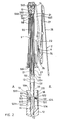
- the present invention comprises: a central shaft means 1, a rib assembly 2, an opening spring 3, a plurality of closing springs 4, and a control means 5.
- the central shaft means 1 includes: an inner (or lower) tube 11, a grip 12 secured to a lower tube portion of the inner tube 11, a middle tube 13 slidably held on an outer and upper side of the inner tube 11, an outer (or upper) tube 14 slidably held on an outer and upper side of the middle tube 13, an upper notch 15 secured on a top portion of the outer tube 14, and a central sleeve set 17 including an inner sleeve section 172, and an outer sleeve section 171 telescopically coupled with the inner sleeve section 172 having an uppermost sleeve portion 171a of the outer sleeve section 171 contiguous to an upper portion of the outer tube 14.
- the rib assembly 2 includes: a top rib 21 having an inner rib portion of the top rib 21 pivotally secured to the upper notch 15 of the central shaft means 1, an inner stretcher rib 22 having an inner rib portion of the inner stretcher rib 22 pivotally secured to a lower runner 23 which is slidably held on the outer tube 14 and having an outermost rib end of the inner stretcher rib 22 pivotally connected with a middle portion of the top rib 21, an intermediate rib 24 having an inner rib end of the intermediate rib 24 pivotally connected with an outermost rib end of the top rib 21 and having an innermost rib end of the intermediate rib 24 pivotally connected with an intermediate connecting rod 25 of which an inner rod end of the intermediate connecting rod 25 is pivotally secured to an outer rib portion of the inner stretcher rib 22, and a rear rib 26 having an inner rib portion of the rear rib 26 pivotally connected with an outer rib portion of the intermediate rib 24 and having an innermost rib end of the rear rib 26 pivotally connected with a spring
- the opening spring 3 for opening an umbrella of this invention has a lower spring end 31 retained on a lower tube portion 10a of the inner tube 11, and an upper spring end 32 retained on a bottom portion of an inner block 151 inserted in an upper portion of the outer tube 14, the opening spring 3 slidably disposed about the central sleeve set 17.
- Each closing spring 4 of the plurality of the closing springs 4 has an inner spring end 41 of the closing spring 4 secured to an inner portion of the intermediate connecting rod 25, and an outer spring end 42 of the closing spring 4 secured to an outer rib portion of the top rib 21.
- the closing spring 4 is provided for operatively closing an umbrella from its opened state by an elastic energy stored when opening the umbrella.
- Other locations for installing the closing spring 4 on the rib means 2 may be modified.
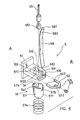
- the control means 5 includes: a push button 51 resiliently held in a button hole 120a formed in the grip 12, an upper latch 52 slidably held in a slotted plate 510 perpendicularly protruding from a middle button portion of the push button 51 from a first side A of the central shaft means 1 towards a second side B of the shaft means 1 and operatively depressed by the push button 51 for opening the umbrella, a closing controller 53 having a lower latch 54 resiliently held in the grip 12 and operatively depressible by the push button 51 for inwardly pushing a locking head 551, which is secured with a drag rod 55 coupled to a drag rope 56 which is linked through the lower runner 23 to an upper portion of the outer tube 14, for disengaging the locking head 551 from a detent protrusion 111a formed in a lower portion of the inner tube 11, thereby allowing each said closing spring 4 to be restored to release its pre-stored elastic energy for closing the umbrella from an opened state, with the lower latch 54 resiliently secured to an anti-false operation
- the slotted plate 510 of the button 51 may be slidably held in a groove 124 transversely formed in the grip 12.
- the upper latch 52 includes: a pair of bifurcated arm members 523 slidably held in two sliding slots 514 juxtapositionally formed in the slotted plate 510 of the push button 51 as bifurcated from an upper latch portion 522 formed on the upper latch 52 adjacent to the second side B of the shaft means 1 and with the pair of arm members 523 protruding from the upper latch portion 522 at the second side B of the shaft means 1 towards the first side A of the shaft means 1 to be contacted with a pair of end walls 512 of the two sliding slots 514 ready for a depression by the push button 51 when opening the umbrella, and the upper latch portion 522 secured with a stem 524 protruding towards the second side B of the shaft means 1 to be resiliently urged towards the first side A of the shaft means 1 by a restoring spring 50 retained in the grip 12 adjacent to the second side B of the shaft means 1 to be engageable with a lower hole 141 formed in the outer tube 14, and a lower hole 131 formed in the middle tube 13 for locking an umbrella under a closed
- the push button 51 has the slotted plate 510 formed with a central plate hole 510a in a central portion of the slotted plate 510 for downwardly passing a bottom tube portion of each outer tube 14 and middle tube 13 when folding the central shaft means 1 for closing the umbrella ( Figure 4), a latch notch 515 recessed in an end portion of the slotted plate 510 adjacent to the second side B for slidably holding the upper latch portion 522 in the latch notch 515 and a central thrusting block 513 formed on a central portion inside the push button 51 and protruding inwardly towards the second side B of the shaft means 1.
- the umbrella Upon an inward depression of the push button 51 to allow the end walls 512 of the slotted plate 510 of the push button 51 to retract the bifurcated arm members 523 for disengaging the upper latch portion 522 from the lower holes 141, 131 of the outer, and middle tubes 14, 13, the umbrella will be opened because the tubes of the shaft means 1 are resiliently tensioned by the opening spring 3.
- the closing controller 53 includes: the lower latch 54 resiliently secured to the anti-false operation safety means 57 by a spring plate 540 and resiliently raised upwardly as urged by a tension spring 57a of the safety means 57 to be positioned in between a central thrusting block 513 of the push button 51 and a locking head 551 secured with the drag rod 55 when opening the umbrella as shown in Figure 6, with the central plate hole 510a in the slotted plate 510 allowing an upwardly moving of the lower latch 54 as urged by the cylinder 571 and tension spring 57a after opening the umbrella to extend the outer and middle tubes 14, 13 upwardly as shown in Figure 6, whereby upon depression of the push button to inwardly thrust the central thrusting block 513 formed on the central portion inside the button 51, the locking head 551 will be disengaged from the detent protrusion 111a in the inner tube 11 for closing an umbrella from an opened state.
- the detent protrusion 111a is directly punched inwardly from a lower portion of the inner tube 11 for engaging the locking head 551 when closing the umbrella as sidewards biased towards the first side A of the shaft means 1 by a convex spring plate 58 formed in the grip 12 at the second side B of shaft means 1.
- the drag rod 55 has a lower rod end secured to the locking head 551 and an upper rod end 552 pivotally secured in a coupling sleeve 560, with an inner rope end 561 of the drag rope 56 secured in the coupling sleeve 560, and with the drag rod 55 slidably held in the inner sleeve section 172 of the central sleeve set 17.
- the drag rope 56 includes: the lower rope end 561 coupled to the drag rod 55 by the coupling sleeve 560, an upper rope end 562 fixed to a top portion 152 of the outer tube 14 and in the upper notch 15, an upper guiding roller 563 rotatably mounted by a upper pivot 16 in the inner block 151 secured in a top portion of the outer tube 14 and in the upper notch 15 for slidably guiding the drag rope 56 from inside the outer tube 14 and the central sleeve set 17 telescopically held within the inner tube 11, the middle tube 13, and the outer tube 14 through the upper guiding roller 563 towards a lower guiding roller 564 through a rope passage 150 formed in the upper notch 15, the rope 56 with an upper rope section passing through the lower guiding roller 564 to have the upper rope end 562 fixed to the top portion 152 of the outer tube 14 and inside the inner block 151.
- the lower guiding roller (564) is rotatably mounted in a socket formed in a bottom portion of the lower runner (23).
- the lower guiding roller (564) may also be rotatably mounted in a roller holder (not shown) secured in the lower runner (23) for a synchronous sliding movement of the lower runner (23) and the roller holder on the central shaft means (1).
- a bottom plug (not shown) as positioned under the roller holder may be embedded into the socket in the bottom portion of the lower runner (23) for sealing the roller holder and the lower guiding roller (564) in the lower runner (23).
- the anti-false operation safety means 57 includes: a cylinder 571 slidably disposed around a lower portion of the inner tube 11 and resiliently rested on a tension spring 57a retained in a lower portion of the grip 12, the cylinder 571 having a spring plate 540 protruding upwardly to connect the lower latch 54 which is downwardly moved when closing the umbrella for preventing a false operation of the closing controller 53 when the central shaft means 1 is folded to lower the outer and middle tubes 14, 13 to allow a bottom end of each middle tube 13 and outer tube 14 to downwardly press the lower latch 54, the cylinder 571 and the tension spring 57a downwardly for restoring the spring energy of the tension spring 57a as shown in Figure 4 whereby the outer and middle tubes 14, 13 are locked by engaging the upper latch portion 522 with the lower holes 141, 131 of the tubes 14, 13, a first slot 574 notched in a first side of the cylinder for an inward movement of the lower latch 54 connected to the cylinder 571 by the spring plate 540 adjacent to the first side
- the convex spring plate 58 has an upper and a lower spring end 581, 582 fixed in the inner tube 11 inserted into the inner hole 120 of the grip 12, with a sloping spring portion 580 inclined downwardly from the upper spring end 581 to an axis of the shaft means 1 for biasing the locking head 551 to be locked on the detent protrusion 111a formed in the inner tube 11 adjacent to the first side A of the shaft means 1 when closing the umbrella ( Figure 3).
- the push button 51 When opening the umbrella of the present invention as shown from Figure 3 to Figure 1, the push button 51 is depressed (O) to allow the end walls 512 of the slotted plate 510 to force the bifurcated arms 523 inwardly to disengage the upper latch portion 522 from the holes 141, 131 formed in the tubes 14, 13 of the shaft means 1 to release the opening spring 3, which is previously compressed when re-setting the umbrella for storing the elastic energy of the opening spring as shown in Figure 3, to extend the tubes 14, 13, 11 and open the ribs of the rib assembly 2 for opening the umbrella.
- the closing springs 4 are also tensioned to store their restoring elastic energy by the opening operation of the umbrella as effected by the opening spring 3.
- the push button 51 When closing the umbrella from Figure 1 to Figure 2, the push button 51 is depressed (C) to allow the central thrusting block 513 of the button 51 to force the lower latch 54 of the closing controller 53 towards the second side B of shaft means 1 to disengage the locking head 551 from the detent protrusion 111a formed in the inner tube 11 to allow a downward movement of the runner 23 required for closing the umbrella, and the closing springs 4 will restore to lower the runner 23 to retract the ribs of the rib assembly 2 and fold the tubes 14, 13, 11 as shown in Figure 2.
- the locking head 551 will then be raised to be stopped at a lower sleeve portion 172a of the sleeve set 17.
- the grip 12 may be depressed (D) towards a tip portion of the umbrella ( Figure 2 to Figure 3) for compressing the spring 3 ready for next opening use.
- the present invention may be used for an automatic umbrella having triple folds or multiple folds.
- the present invention is superior to the U. S. patent 5,492,140 with the following advantages:
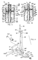
- FIG. 9 - 11 Another preferred embodiment of the present invention is shown in Figures 9 - 11, in which the control means 5 has been modified from the aforementioned to omit the safety means 57 and to modify the lower latch 54a to be pivotally secured to the push button 51.
- the lower latch 54a includes: a pin 540a secured at a base portion of the slotted plate 510 of the push button 51 for pivotally mounting the lower latch 54a at a middle inside portion of the button 51, a latch restoring spring 543 retained on the push button 51 for normally levelling the lower latch 54a to be generally perpendicular to the push button to allow an arcuate latch end 541 formed at an inner free end of the lower latch 54a to depress the locking head 551 to be disengaged from the detent protrusion 111a when closing (C) the umbrella ( Figure 10).
- the lower latch 54a is downwardly biased (B) by the bottom tube ends of the outer tube 14 and middle tube 13 when closing and resetting the umbrella for storing energy of the opening spring 3 as shown in Figure 9, thereby allowing an inward depression of the push button 51 to open (O) the umbrella as shown in Figure 9. Also, the downwardly biased (B) lower latch 54 will not depress the locking head 551 to prevent false operation for closing the umbrella.
- the upper latch 52 and the lower latch 54 of the present invention may also be designated as the opening latch 52 and the closing latch 54 respectively.
Landscapes
- Walking Sticks, Umbrellas, And Fans (AREA)
Applications Claiming Priority (2)
| Application Number | Priority Date | Filing Date | Title |
|---|---|---|---|
| US511970 | 1995-08-07 | ||
| US08/511,970 US5505222A (en) | 1995-08-07 | 1995-08-07 | Multiple-fold automatic umbrella with simplified control means |
Publications (2)
| Publication Number | Publication Date |
|---|---|
| EP0761120A1 true EP0761120A1 (de) | 1997-03-12 |
| EP0761120B1 EP0761120B1 (de) | 2000-01-26 |
Family
ID=24037160
Family Applications (1)
| Application Number | Title | Priority Date | Filing Date |
|---|---|---|---|
| EP96303449A Expired - Lifetime EP0761120B1 (de) | 1995-08-07 | 1996-05-15 | Mehrfach faltbarer Automatikschirm mit vereinfachter Bedienung |
Country Status (3)
| Country | Link |
|---|---|
| US (1) | US5505222A (de) |
| EP (1) | EP0761120B1 (de) |
| DE (1) | DE29609283U1 (de) |
Families Citing this family (24)
| Publication number | Priority date | Publication date | Assignee | Title |
|---|---|---|---|---|
| CN2258710Y (zh) * | 1996-02-08 | 1997-08-06 | 周龙交 | 动能动程变比式多节中棒定位型自动张收伞 |
| US5626161A (en) * | 1996-04-29 | 1997-05-06 | Fu Tai Umbrella Works, Ltd. | Multiple-fold automatic umbrella with simplified reliable control means |
| US5645094A (en) * | 1996-05-28 | 1997-07-08 | Wu; Woh-Wen | Multiple-fold automatic umbrella with reinforced ribs and simplified mechanism |
| US5617889A (en) * | 1996-05-28 | 1997-04-08 | Wu; Woh-Wen | Multiple-fold automatic umbrella with reinforced ribs and simplified mechanism |
| US5632290A (en) * | 1996-08-16 | 1997-05-27 | Ling Kuo; Cheng M. | Automatically collapsible umbrellas |
| DE19636690C1 (de) * | 1996-09-10 | 1997-11-27 | Kortenbach Verwaltung | Automatisch öffnender und schließender, auf Taschenformat verkürzbarer Schirm |
| US5720311A (en) * | 1996-10-07 | 1998-02-24 | Fu Tai Umbrella Works, Ltd. | Telescopic umbrella shaft means with concave hexagonal sides |
| GB2325405A (en) * | 1997-05-21 | 1998-11-25 | Ko Chin Sung | Automatic umbrella control cord mechanism |
| US5758677A (en) * | 1997-06-05 | 1998-06-02 | Wang; Shen Ho | Umbrella structure for controlling an automatic opening |
| US5803102A (en) * | 1997-09-09 | 1998-09-08 | Ko; Chin-Sung | Protecting structure of control members of a folded umbrella |
| US5868151A (en) * | 1998-04-02 | 1999-02-09 | Kuo; Cheng Miao Ling | Controlling apparatus of an umbrella |
| US6016822A (en) * | 1998-04-28 | 2000-01-25 | Fu Tai Umbrella Works, Ltd. | Automatic umbrella with quadruple folds or the like |
| US6324310B1 (en) | 1998-06-02 | 2001-11-27 | Digital Persona, Inc. | Method and apparatus for scanning a fingerprint using a linear sensor |
| US6188781B1 (en) | 1998-07-28 | 2001-02-13 | Digital Persona, Inc. | Method and apparatus for illuminating a fingerprint through side illumination of a platen |
| US6112755A (en) * | 1998-12-15 | 2000-09-05 | Fu Tai Umbrella Works, Ltd. | Automatic penta-fold umbrella |
| US6257257B1 (en) * | 1999-12-16 | 2001-07-10 | Jia-Ling Shih | Automatic opening and closing structure of a collapsible umbrella |
| US6684893B2 (en) * | 2001-10-01 | 2004-02-03 | Shih-Shin Kuo | Simplified controlling apparatus of an automatic umbrella |
| RU2231274C2 (ru) * | 2003-01-09 | 2004-06-27 | Филатов Сергей Иванович | Зонт |
| US20060032523A1 (en) * | 2004-08-10 | 2006-02-16 | Lung-Chiao Chou | Automated-open-close umbrella |
| US20080178919A1 (en) * | 2007-01-31 | 2008-07-31 | Shun-Fu Yang | Automated awning |
| CN101785597B (zh) * | 2009-10-26 | 2012-07-18 | 厦门福太洋伞有限公司 | 一种直骨自动伞的改良结构 |
| EP2572602B1 (de) * | 2011-09-26 | 2014-07-02 | Peter Su | Wellenstruktur eines automatischen Regenschirms |
| CN107582289B (zh) * | 2017-09-28 | 2023-05-05 | 新海科技集团有限公司 | 护理机的集污装置 |
| CN111736290B (zh) | 2020-06-23 | 2022-03-11 | 武汉光迅科技股份有限公司 | 一种透镜夹持装置 |
Citations (6)
| Publication number | Priority date | Publication date | Assignee | Title |
|---|---|---|---|---|
| DE4120001A1 (de) * | 1990-08-08 | 1992-02-13 | Totes Inc | Schirm |
| EP0498986A2 (de) * | 1991-02-15 | 1992-08-19 | Fu Tai Umbrella Works, Ltd. | Automatischer Schirm mit einem in gerader Linie zu bewegenden Druckknopf zum Öffnen und Schliessen des Schirmes |
| DE9215806U1 (de) * | 1992-11-20 | 1993-01-07 | Wu, Woh-Wen, Tai-San Hsiang, Taipeh | Mehrfach faltbarer Automatikschirm mit Einknopf-Bedienung |
| US5178174A (en) * | 1992-03-30 | 1993-01-12 | Wu Woh Wen | Silently smoothly operating automatic umbrella controlled by single push button |
| US5232004A (en) * | 1992-09-21 | 1993-08-03 | Wu Woh Wen | Automatic umbrella having wind-resistant buffer effect |
| US5492140A (en) * | 1995-07-28 | 1996-02-20 | Fu Tai Umbrella Works, Ltd. | Multiple-fold automatic umbrella with simplified grip |
Family Cites Families (8)
| Publication number | Priority date | Publication date | Assignee | Title |
|---|---|---|---|---|
| US4548222A (en) * | 1984-02-16 | 1985-10-22 | Day San Tong | Full-automatic umbrella |
| US4936332A (en) * | 1989-10-23 | 1990-06-26 | Wu Tsun Zong | Simply-constructed automatic umbrella for preventing false operation |
| US4986294A (en) * | 1989-10-23 | 1991-01-22 | Wu Tsun Zong | Automatic umbrella having smoothly-operating springs |
| US4941494A (en) * | 1989-10-23 | 1990-07-17 | Wu Tsun Zong | Lightly-operating automatic umbrella for preventing false operation |
| US4989625A (en) * | 1990-09-07 | 1991-02-05 | Wu Tsun Zong | Stably-retained automatic umbrella |
| US5174319A (en) * | 1992-06-17 | 1992-12-29 | Dat, Sheng-Tong | Longer effective automatic umbrella |
| US5224505A (en) * | 1992-09-08 | 1993-07-06 | Fu Tai Umbrella Works, Ltd. | Automatic umbrella with upwardly and downwardly thrusted push button |
| US5390686A (en) * | 1993-11-08 | 1995-02-21 | Lin; Chung-Kuang | Multiple-fold automatic umbrella |
-
1995
- 1995-08-07 US US08/511,970 patent/US5505222A/en not_active Expired - Lifetime
-
1996
- 1996-05-15 EP EP96303449A patent/EP0761120B1/de not_active Expired - Lifetime
- 1996-05-23 DE DE29609283U patent/DE29609283U1/de not_active Expired - Lifetime
Patent Citations (6)
| Publication number | Priority date | Publication date | Assignee | Title |
|---|---|---|---|---|
| DE4120001A1 (de) * | 1990-08-08 | 1992-02-13 | Totes Inc | Schirm |
| EP0498986A2 (de) * | 1991-02-15 | 1992-08-19 | Fu Tai Umbrella Works, Ltd. | Automatischer Schirm mit einem in gerader Linie zu bewegenden Druckknopf zum Öffnen und Schliessen des Schirmes |
| US5178174A (en) * | 1992-03-30 | 1993-01-12 | Wu Woh Wen | Silently smoothly operating automatic umbrella controlled by single push button |
| US5232004A (en) * | 1992-09-21 | 1993-08-03 | Wu Woh Wen | Automatic umbrella having wind-resistant buffer effect |
| DE9215806U1 (de) * | 1992-11-20 | 1993-01-07 | Wu, Woh-Wen, Tai-San Hsiang, Taipeh | Mehrfach faltbarer Automatikschirm mit Einknopf-Bedienung |
| US5492140A (en) * | 1995-07-28 | 1996-02-20 | Fu Tai Umbrella Works, Ltd. | Multiple-fold automatic umbrella with simplified grip |
Also Published As
| Publication number | Publication date |
|---|---|
| DE29609283U1 (de) | 1996-09-26 |
| US5505222A (en) | 1996-04-09 |
| EP0761120B1 (de) | 2000-01-26 |
Similar Documents
| Publication | Publication Date | Title |
|---|---|---|
| EP0761120B1 (de) | Mehrfach faltbarer Automatikschirm mit vereinfachter Bedienung | |
| US5492140A (en) | Multiple-fold automatic umbrella with simplified grip | |
| US5390686A (en) | Multiple-fold automatic umbrella | |
| US5626161A (en) | Multiple-fold automatic umbrella with simplified reliable control means | |
| US6016822A (en) | Automatic umbrella with quadruple folds or the like | |
| US6112755A (en) | Automatic penta-fold umbrella | |
| EP0425071B1 (de) | Automatischer Schirm | |
| US5740823A (en) | Lightening safety automatic umbrella | |
| EP0156045B1 (de) | Völlig automatischer Schirm mit einem einzigen Druckknopf | |
| US5267583A (en) | Multiple-fold automatic umbrella controlled by single push button | |
| US5992433A (en) | Multiple-fold automatic umbrella with simplified control mechanism and minimized elements | |
| US4989625A (en) | Stably-retained automatic umbrella | |
| US5178174A (en) | Silently smoothly operating automatic umbrella controlled by single push button | |
| US6360759B1 (en) | Multiple-fold automatic umbrella with penta-fold rope | |
| US6176246B1 (en) | Multiple-fold automatic umbrella with simplified structure and shortened length | |
| CA2047974C (en) | Lightly operable fully automatic umbrella | |
| CA2132600C (en) | Reliably operated automatic umbrella with upwardly and downwardly thrusted push button | |
| US4936332A (en) | Simply-constructed automatic umbrella for preventing false operation | |
| US5161562A (en) | Umbrella with simplified automatic closing mechanism | |
| US5078165A (en) | Automatic umbrella opened and closed by a straightforward push button | |
| JP2945389B1 (ja) | 多段折畳み式自動開閉傘 | |
| US5318067A (en) | Simplified fully automatic umbrella | |
| US5247955A (en) | Ergonomically operating automatic umbrella | |
| JP3023100B2 (ja) | 多段折畳み式自動開閉傘 | |
| JP3026909U (ja) | 多段式自動折畳み傘 |
Legal Events
| Date | Code | Title | Description |
|---|---|---|---|
| PUAI | Public reference made under article 153(3) epc to a published international application that has entered the european phase |
Free format text: ORIGINAL CODE: 0009012 |
|
| AK | Designated contracting states |
Kind code of ref document: A1 Designated state(s): FR GB |
|
| 17P | Request for examination filed |
Effective date: 19970423 |
|
| GRAG | Despatch of communication of intention to grant |
Free format text: ORIGINAL CODE: EPIDOS AGRA |
|
| GRAG | Despatch of communication of intention to grant |
Free format text: ORIGINAL CODE: EPIDOS AGRA |
|
| GRAH | Despatch of communication of intention to grant a patent |
Free format text: ORIGINAL CODE: EPIDOS IGRA |
|
| 17Q | First examination report despatched |
Effective date: 19990505 |
|
| GRAH | Despatch of communication of intention to grant a patent |
Free format text: ORIGINAL CODE: EPIDOS IGRA |
|
| GRAA | (expected) grant |
Free format text: ORIGINAL CODE: 0009210 |
|
| RBV | Designated contracting states (corrected) |
Designated state(s): FR GB |
|
| AK | Designated contracting states |
Kind code of ref document: B1 Designated state(s): FR GB |
|
| ET | Fr: translation filed | ||
| PLBE | No opposition filed within time limit |
Free format text: ORIGINAL CODE: 0009261 |
|
| STAA | Information on the status of an ep patent application or granted ep patent |
Free format text: STATUS: NO OPPOSITION FILED WITHIN TIME LIMIT |
|
| 26N | No opposition filed | ||
| REG | Reference to a national code |
Ref country code: GB Ref legal event code: IF02 |
|
| PGFP | Annual fee paid to national office [announced via postgrant information from national office to epo] |
Ref country code: GB Payment date: 20050505 Year of fee payment: 10 |
|
| PGFP | Annual fee paid to national office [announced via postgrant information from national office to epo] |
Ref country code: FR Payment date: 20050525 Year of fee payment: 10 |
|
| PG25 | Lapsed in a contracting state [announced via postgrant information from national office to epo] |
Ref country code: GB Free format text: LAPSE BECAUSE OF NON-PAYMENT OF DUE FEES Effective date: 20060515 |
|
| GBPC | Gb: european patent ceased through non-payment of renewal fee |
Effective date: 20060515 |
|
| REG | Reference to a national code |
Ref country code: FR Ref legal event code: ST Effective date: 20070131 |
|
| PG25 | Lapsed in a contracting state [announced via postgrant information from national office to epo] |
Ref country code: FR Free format text: LAPSE BECAUSE OF NON-PAYMENT OF DUE FEES Effective date: 20060531 |