EP0498995A2 - Système de commande de transfert de données - Google Patents
Système de commande de transfert de données Download PDFInfo
- Publication number
- EP0498995A2 EP0498995A2 EP91311443A EP91311443A EP0498995A2 EP 0498995 A2 EP0498995 A2 EP 0498995A2 EP 91311443 A EP91311443 A EP 91311443A EP 91311443 A EP91311443 A EP 91311443A EP 0498995 A2 EP0498995 A2 EP 0498995A2
- Authority
- EP
- European Patent Office
- Prior art keywords
- command data
- code
- setting command
- units
- controller
- Prior art date
- Legal status (The legal status is an assumption and is not a legal conclusion. Google has not performed a legal analysis and makes no representation as to the accuracy of the status listed.)
- Granted
Links
Images


Classifications
-
- G—PHYSICS
- G06—COMPUTING OR CALCULATING; COUNTING
- G06F—ELECTRIC DIGITAL DATA PROCESSING
- G06F3/00—Input arrangements for transferring data to be processed into a form capable of being handled by the computer; Output arrangements for transferring data from processing unit to output unit, e.g. interface arrangements
- G06F3/14—Digital output to display device ; Cooperation and interconnection of the display device with other functional units
- G06F3/1423—Digital output to display device ; Cooperation and interconnection of the display device with other functional units controlling a plurality of local displays, e.g. CRT and flat panel display
-
- H—ELECTRICITY
- H04—ELECTRIC COMMUNICATION TECHNIQUE
- H04N—PICTORIAL COMMUNICATION, e.g. TELEVISION
- H04N5/00—Details of television systems
- H04N5/74—Projection arrangements for image reproduction, e.g. using eidophor
-
- H—ELECTRICITY
- H04—ELECTRIC COMMUNICATION TECHNIQUE
- H04N—PICTORIAL COMMUNICATION, e.g. TELEVISION
- H04N9/00—Details of colour television systems
- H04N9/12—Picture reproducers
-
- G—PHYSICS
- G06—COMPUTING OR CALCULATING; COUNTING
- G06F—ELECTRIC DIGITAL DATA PROCESSING
- G06F3/00—Input arrangements for transferring data to be processed into a form capable of being handled by the computer; Output arrangements for transferring data from processing unit to output unit, e.g. interface arrangements
- G06F3/14—Digital output to display device ; Cooperation and interconnection of the display device with other functional units
- G06F3/1423—Digital output to display device ; Cooperation and interconnection of the display device with other functional units controlling a plurality of local displays, e.g. CRT and flat panel display
- G06F3/1446—Digital output to display device ; Cooperation and interconnection of the display device with other functional units controlling a plurality of local displays, e.g. CRT and flat panel display display composed of modules, e.g. video walls
-
- H—ELECTRICITY
- H04—ELECTRIC COMMUNICATION TECHNIQUE
- H04N—PICTORIAL COMMUNICATION, e.g. TELEVISION
- H04N9/00—Details of colour television systems
- H04N9/12—Picture reproducers
- H04N9/31—Projection devices for colour picture display, e.g. using electronic spatial light modulators [ESLM]
- H04N9/3141—Constructional details thereof
- H04N9/3147—Multi-projection systems
Definitions
- the present invention relates to a system for controlling a plurality of units by transferring serial data from a computer. More particularly, the invention is directed to a control system suitable for controlling a display system consisting of a plurality of display units, e.g., projection TVs.
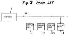
- a first example is such that a single distributor 7 is interposed between a computer 1 and each of display units U1-U4, and that transmission data from the computer 1 is selectively distributed to either one of the display units U1-U4 by the distributor 7.
- the selection among the display units U1-U4 involves the process that the distributor 7 decodes an identification code (hereinafter referred to as "ID code") included in the transmission data, which code serves to identify one of the display units U1-U4.
- ID code an identification code
- Data succeeding the ID code is thereafter taken by, e.g., the display unit U1, which then adjusts the luminance or color of an image as instructed by the data.
- a second example is such that a computer 1 is connected to each of display units U1-U4 via a bus 8.
- Specific ID codes are preassigned to the respective display units U1-U4, and an ID code included in transmission data from the computer 1 is decoded by each display unit. If the ID code indicates that the transmission data is directed to, e.g., the display unit U1, the display unit U1 takes in the transmission data.
- each of the display units U1-U4 must be provided with setting switches and a memory such as a ROM for setting and storing its own ID code, respectively.
- a network must include the distributor 7 to select from among the display units U1-U4, thus increasing number of components.
- the number of display units distributable by a single distributor 7 is limited, so that additional distributors may have to be provided to increase the number of display units. This makes it difficult to expand a system.
- each of the display units U1-U4 must be provided with hardware such as setting switches for setting an ID code and a ROM for storing the same, again unavoidably increasing the number of components.
- a signal attenuates as it goes farther away from the computer 1. This means that there exists a limit of the signal line length, which further imposes a certain limit on display unit expandability.
- ID codes may have to be reassigned or changed over the entire network, depending on the installation position of the additional display units. In such a case, a cumbersome operation of reassigning the ID codes of the respective display units must be performed.
- an object of the present invention is to provide a data transfer control system that is readily expandable without requiring any special components.
- a data transfer control system for controlling transmission of serial command data to a plurality of units connected in series, comprises: computer means for transmitting identification setting command data for the respective units in a sequential manner; and means, at each of the plurality of units, for taking in an identification code included in first-received identification setting command data to employ it as an identification code of an associated unit, and for transferring subsequently received identification setting command data to a following unit.
- the invention is intended to adjust controlling items of individual units or those of a system as a whole.
- the white balance, brightness, contrast, etc. of respective display units are adjusted individually or those of the display system are adjusted as a whole.
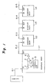
- Figure 1 shows a transfer control system according to an embodiment of the invention.
- a plurality of display units U1-U4 are connected to a computer 1 in series via a communication line 6-1 of, e.g., RS-232C and communication lines 6-2 to 6-5 of, e.g., a DIN cable.
- the display unit U1 includes: a buffer amplifier 2 for amplifying a level of transmission data received via an input terminal IN; a controller 5 in the form of a microprocessor for controlling the entire display unit U1 based on the transmission data provided via an input port 9; an AND gate 3 for controlling transfer of the transmission data output from the buffer amplifier 2 based on a transfer permission signal A output from an control port 10 of the controller 5; and a buffer amplifier 4 for providing, after amplification, the transmission data output from the AND gate 3 to an output terminal OUT.
- Each of the other display units U2-U4 has the same construction, that is, each has the buffer amplifier 2, AND gate 3, buffer amplifier 4, and controller 5.
- transmission data is transmitted serially based on, e.g., an RS-232C communication system.
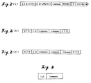
- Figure 2(a) shows an exemplary communication format.
- the format includes in the order as written: a STX (start of transmission) code indicating the head of the data; an ID code indicating the transmission destination, i.e., (one of) the display units U1-U4; command data indicating a content of control; and an ETX (end of transmission) code indicating the end of the data.
- a plurality of command data can be transmitted in succession as shown in Figures 2(b) and 2(c).
- the ID code is made up of two characters selected from numerals 0 to 9 and alphabetical characters A, B, C, D, E and F, to constitute an ID code for indicating a display unit.
- the ID code may include one or two asterisks * in certain situations. For example, for an ID code "3A” indicating a certain display unit, valid ID codes are "3A", “*A”, "3*" and "**".
- commands are: “PON” (power on) for turning on power; “POF” (power off) for turning off power; "IN1” for switching an input to a video signal; “IN2” for switching an input to a Y/C signal; “CM1” for switching an operation mode to a white balance adjustment-1; “AJY” (adjust yes) for selecting an adjustment mode; and “AJN” (adjust no) for selecting a normal mode.
- commands are to be preset.
- FIG. 3 An exemplary serial data format is shown in Figure 3.
- "id” represents an ID code of intended one of the display units U1-U4. For example, if the ID code of the intended display unit U1 is “11”, “id” should be “11”. Similarly, if the ID code of the intended display unit U2 is “12", “id” should be “12”.
- "command” represents data of an ID code setting instruction, e.g., "IDS” (ID set). Further, to set new ID codes for the respective display units U1-U4, it is necessary that the current ID codes be cleared. A command for such a purpose is, e.g., "IDC” (ID clear).
- the controller 5 of each of the display units U1-U4 executes an algorithm shown in Figure 5.
- the controller 5 judges whether or not an ID code has been set (Step 100). Since this is the initializing operation, the answer is "No", and the controller 5 proceeds to Step 103.
- Step 103 the controller 5 judges whether or not the transmitted serial data is the ID setting command data. Since this is the initializing operation, the answer is "Yes”, and the controller 5 employs a content "id" of the transmitted command data as its own ID code. For example, if the first-sent command data is "11IDS", the controller 5 of the first display unit U1 recognizes that its ID code is to be determined as "11”, and stores the ID code "11” into a memory of the controller 5.
- the controller 5 controls the display unit U1 in accordance with the command included in that communication data.
- the controller 5 Upon completion of setting the ID code for the display unit U1, the controller 5 outputs a transfer permission signal A of a logic level "H" to the AND gate 3 from its control port 10 (Step 105).
- the AND gate 3 its input condition being satisfied, opens its gate and transfers next command data "12IDS" to the following display unit U2.
- the display unit U2 executes Steps 100, 103, 104 in this order to take in the ID code "12", outputs an "H" level transfer permission signal A from its controller 5, and transfers a next command "21IDS" to the display unit U3.
- the premiss of that operation i.e., the output of the control port 10 is shown in a flow chart of Figure 6. That is, during the initializing operation, the controller 5 of a display unit maintains a logic level "L" of its control port 10 until the ID code of the own display unit is set. Upon completion of setting the ID code, the controller 5 transfers subsequent serial data to the following display unit.
- the controller 5 executes a command as instructed following Steps 100 (Yes), 101 and 102 in Figure 5.
- Commands to be executed in this case are, e.g., "PON” for turning on a power, and "CM1" for switching an operation mode, as described above.
- the ID codes of the respective display units U1-U4 are cleared by the command data "**IDC", and then the "IDS" command data for initialization are sequentially transmitted from the computer 1, so that the respective display units U1-U4 automatically take in and set their own ID codes.
- no distributor is required as in the conventional example, nor are separate ID code setting switches and ROMs for the respective display units U1-U4, thereby allowing ID codes to be set only by preparing command data to be sent from the computer 1 (i.e., only by making an appropriate program). This not only facilitates the ID code setting when additional display units are provided, but also gives a higher degree of freedom in system expansion.
- each of the units to be controlled takes in a first-received ID code and recognizes that ID code as its own ID code, and then transfers a next ID code to a following unit via a transfer gate after having recognized the first ID code as its own ID code. Therefore, the system can be expanded without using any special components as would be required in the prior art.
- a buffer amplifier is disposed on both the input and output sides of each display unit, signal level attenuation can be prevented even if the communication line becomes longer, thereby allowing the system to be expanded without causing defective operations.
- the serial data transmission of the invention allows data to be transmitted by, e.g., a pair of lines twisted.
- the respective display units can be connected in a cascade manner, the system construction can be simplified.
Landscapes
- Engineering & Computer Science (AREA)
- Multimedia (AREA)
- Signal Processing (AREA)
- Theoretical Computer Science (AREA)
- Human Computer Interaction (AREA)
- Physics & Mathematics (AREA)
- General Engineering & Computer Science (AREA)
- General Physics & Mathematics (AREA)
- Controls And Circuits For Display Device (AREA)
- Selective Calling Equipment (AREA)
- Information Transfer Systems (AREA)
- Small-Scale Networks (AREA)
Applications Claiming Priority (2)
| Application Number | Priority Date | Filing Date | Title |
|---|---|---|---|
| JP3041182A JP2501965B2 (ja) | 1991-02-12 | 1991-02-12 | デ―タ転送制御装置 |
| JP41182/91 | 1991-02-12 |
Publications (3)
| Publication Number | Publication Date |
|---|---|
| EP0498995A2 true EP0498995A2 (fr) | 1992-08-19 |
| EP0498995A3 EP0498995A3 (en) | 1993-05-05 |
| EP0498995B1 EP0498995B1 (fr) | 1997-09-10 |
Family
ID=12601281
Family Applications (1)
| Application Number | Title | Priority Date | Filing Date |
|---|---|---|---|
| EP91311443A Expired - Lifetime EP0498995B1 (fr) | 1991-02-12 | 1991-12-09 | Système de commande de transfert de données |
Country Status (4)
| Country | Link |
|---|---|
| US (1) | US5987532A (fr) |
| EP (1) | EP0498995B1 (fr) |
| JP (1) | JP2501965B2 (fr) |
| DE (1) | DE69127612T2 (fr) |
Cited By (6)
| Publication number | Priority date | Publication date | Assignee | Title |
|---|---|---|---|---|
| WO1997014133A3 (fr) * | 1995-09-27 | 1997-08-28 | Cirrus Logic Inc | Circuits, systemes et procedes pour topographie memoire, et systems de commande d'affichage les utilisant |
| GB2316593A (en) * | 1996-08-21 | 1998-02-25 | Samsung Electronics Co Ltd | Apparatus and method for controlling sub monitors in a video communication system |
| EP0899651A2 (fr) | 1997-08-29 | 1999-03-03 | Xerox Corporation | Affichages par zone dynamiquement réallouable |
| WO2004111830A1 (fr) * | 2003-06-11 | 2004-12-23 | Clearcube Technology, Inc. | Mise a jour selective d'un affichage dans un systeme a ecrans multiples |
| EP1118977A4 (fr) * | 1999-05-27 | 2005-06-15 | Seiko Epson Corp | Affichage par projection |
| US20170139664A1 (en) * | 2015-11-12 | 2017-05-18 | Samsung Electronics Co., Ltd. | Display apparatus and control method thereof |
Families Citing this family (16)
| Publication number | Priority date | Publication date | Assignee | Title |
|---|---|---|---|---|
| US6546441B1 (en) * | 1993-01-26 | 2003-04-08 | Logic Controls, Inc. | Point-of-sale system |
| JPH06245267A (ja) * | 1993-02-18 | 1994-09-02 | Fuji Xerox Co Ltd | 機器制御システム |
| JP3526019B2 (ja) * | 1999-11-30 | 2004-05-10 | インターナショナル・ビジネス・マシーンズ・コーポレーション | 画像表示システム、画像表示装置、および画像表示方法 |
| JP3663106B2 (ja) * | 2000-02-28 | 2005-06-22 | 東芝機械株式会社 | データ入出力装置 |
| KR20040013957A (ko) * | 2002-08-09 | 2004-02-14 | 엘지전자 주식회사 | 멀티비전 및 그 화면 구현 방법 |
| KR100449743B1 (ko) * | 2002-10-04 | 2004-09-22 | 삼성전자주식회사 | 상호 진단 기능을 가지는 Chained영상 표시 장치 |
| KR100662450B1 (ko) | 2005-01-14 | 2007-01-02 | 엘지전자 주식회사 | 멀티-스크린 시스템 및 그 구현방법 |
| US20070150924A1 (en) * | 2005-12-06 | 2007-06-28 | Pioneer Corporation | Image display control apparatus, image display system, image display control method, computer program product, sub-display control apparatus for image display system, and image display method |
| US20070162796A1 (en) * | 2006-01-10 | 2007-07-12 | Mediatek Inc. | Method and portable device for testing electronic device |
| JP4783253B2 (ja) * | 2006-09-27 | 2011-09-28 | パナソニック株式会社 | パネル表示装置 |
| US20090094658A1 (en) * | 2007-10-09 | 2009-04-09 | Genesis Microchip Inc. | Methods and systems for driving multiple displays |
| KR20110132055A (ko) * | 2010-06-01 | 2011-12-07 | 삼성전자주식회사 | Id 설정 시스템, id 설정 방법 및 이를 이용한 디스플레이 장치 |
| WO2013186835A1 (fr) * | 2012-06-11 | 2013-12-19 | Necディスプレイソリューションズ株式会社 | Système d'affichage multi-écrans, dispositif d'affichage, appareil de réglage id, et procédé de réglage id |
| KR102206171B1 (ko) * | 2014-10-27 | 2021-01-22 | 엘지전자 주식회사 | 데이지 체인 형태의 멀티비전 및 그의 id할당 방법 |
| JP6275075B2 (ja) * | 2015-04-02 | 2018-02-07 | キヤノン株式会社 | 投影装置、制御方法及びプログラム |
| EP3761163A1 (fr) * | 2019-07-05 | 2021-01-06 | Vestel Elektronik Sanayi ve Ticaret A.S. | Procédé de fonctionnement d'un système d'affichage doté d'une pluralité d'unités d'affichage, et système d'affichage |
Family Cites Families (17)
| Publication number | Priority date | Publication date | Assignee | Title |
|---|---|---|---|---|
| US3879710A (en) * | 1974-03-01 | 1975-04-22 | Rca Corp | Data processor for a loop data communications system |
| US4360870A (en) * | 1980-07-30 | 1982-11-23 | International Business Machines Corporation | Programmable I/O device identification |
| US4493021A (en) * | 1981-04-03 | 1985-01-08 | The United States Of America As Represented By The Administrator Of The National Aeronautics And Space Administration | Multicomputer communication system |
| US4667287A (en) * | 1982-10-28 | 1987-05-19 | Tandem Computers Incorporated | Multiprocessor multisystem communications network |
| US4663706A (en) * | 1982-10-28 | 1987-05-05 | Tandem Computers Incorporated | Multiprocessor multisystem communications network |
| US4773005A (en) * | 1984-09-07 | 1988-09-20 | Tektronix, Inc. | Dynamic address assignment system |
| US4694293A (en) * | 1984-09-18 | 1987-09-15 | Nippon Gakki Seizo Kabushiki Kaisha | Data transmission system |
| JPS61255188A (ja) * | 1985-05-08 | 1986-11-12 | I S S:Kk | ビデオテツクス通信システムの端末機器側でビデオテツクス画面情報と動画/静止画映像を連動して端末機器側で同時に異なつた多種類の画像映像を一つのデイスプレイに表示する装置 |
| US4858112A (en) * | 1985-12-17 | 1989-08-15 | General Electric Company | Interface comprising message and protocol processors for interfacing digital data with a bus network |
| JP2513180B2 (ja) * | 1986-01-13 | 1996-07-03 | ソニー株式会社 | ビデオテックス表示装置 |
| US4835674A (en) * | 1986-07-28 | 1989-05-30 | Bull Hn Information Systems Inc. | Computer network system for multiple processing elements |
| US4750114A (en) * | 1986-07-28 | 1988-06-07 | Honeywell Bull Inc. | Local area network control block |
| CA1280216C (fr) * | 1986-08-05 | 1991-02-12 | At&T Global Information Solutions Company | Protocole d'utilisation de tranches de temps dans la transmission des donnes via un reseau de traitement de donnees |
| JPH0784935B2 (ja) * | 1989-04-12 | 1995-09-13 | ダイキン工業株式会社 | 空気調和装置の運転制御装置 |
| US5175822A (en) * | 1989-06-19 | 1992-12-29 | International Business Machines Corporation | Apparatus and method for assigning addresses to scsi supported peripheral devices |
| US5204669A (en) * | 1990-08-30 | 1993-04-20 | Datacard Corporation | Automatic station identification where function modules automatically initialize |
| US5309504A (en) * | 1991-11-18 | 1994-05-03 | Syntellect Acquisition Corp. | Automated identification of attendant positions in a telecommunication system |
-
1991
- 1991-02-12 JP JP3041182A patent/JP2501965B2/ja not_active Expired - Fee Related
- 1991-12-09 DE DE69127612T patent/DE69127612T2/de not_active Expired - Fee Related
- 1991-12-09 EP EP91311443A patent/EP0498995B1/fr not_active Expired - Lifetime
-
1993
- 1993-12-02 US US08/160,463 patent/US5987532A/en not_active Expired - Fee Related
Cited By (18)
| Publication number | Priority date | Publication date | Assignee | Title |
|---|---|---|---|---|
| US6025840A (en) * | 1995-09-27 | 2000-02-15 | Cirrus Logic, Inc. | Circuits, systems and methods for memory mapping and display control systems using the same |
| US6058464A (en) * | 1995-09-27 | 2000-05-02 | Cirrus Logic, Inc. | Circuits, systems and method for address mapping |
| WO1997014133A3 (fr) * | 1995-09-27 | 1997-08-28 | Cirrus Logic Inc | Circuits, systemes et procedes pour topographie memoire, et systems de commande d'affichage les utilisant |
| GB2316593A (en) * | 1996-08-21 | 1998-02-25 | Samsung Electronics Co Ltd | Apparatus and method for controlling sub monitors in a video communication system |
| GB2316593B (en) * | 1996-08-21 | 2000-04-12 | Samsung Electronics Co Ltd | Apparatus and method for controlling sub monitors in video communication system |
| DE19736244B4 (de) * | 1996-08-21 | 2005-04-14 | Samsung Electronics Co. Ltd. | Gerät und Verfahren zur Steuerung von Unter-Monitoren im Videokommunikationssystem |
| EP0899651A2 (fr) | 1997-08-29 | 1999-03-03 | Xerox Corporation | Affichages par zone dynamiquement réallouable |
| EP0899651A3 (fr) * | 1997-08-29 | 2000-02-23 | Xerox Corporation | Affichages par zone dynamiquement réallouable |
| US6340957B1 (en) | 1997-08-29 | 2002-01-22 | Xerox Corporation | Dynamically relocatable tileable displays |
| US7061476B2 (en) | 1999-05-27 | 2006-06-13 | Seiko Epson Corporation | Projection display apparatus |
| EP1118977A4 (fr) * | 1999-05-27 | 2005-06-15 | Seiko Epson Corp | Affichage par projection |
| US7161557B2 (en) | 2002-04-08 | 2007-01-09 | Clearcube Technology, Inc. | Selectively updating a display in a multi-display system |
| WO2004111830A1 (fr) * | 2003-06-11 | 2004-12-23 | Clearcube Technology, Inc. | Mise a jour selective d'un affichage dans un systeme a ecrans multiples |
| US20170139664A1 (en) * | 2015-11-12 | 2017-05-18 | Samsung Electronics Co., Ltd. | Display apparatus and control method thereof |
| KR20170055636A (ko) * | 2015-11-12 | 2017-05-22 | 삼성전자주식회사 | 디스플레이장치 및 그 제어방법 |
| CN108292201A (zh) * | 2015-11-12 | 2018-07-17 | 三星电子株式会社 | 显示装置及其控制方法 |
| EP3338178A4 (fr) * | 2015-11-12 | 2019-01-02 | Samsung Electronics Co., Ltd. | Appareil d'affichage et son procédé de commande |
| US10416951B2 (en) | 2015-11-12 | 2019-09-17 | Samsung Electronics Co., Ltd. | Display apparatus and control method thereof |
Also Published As
| Publication number | Publication date |
|---|---|
| US5987532A (en) | 1999-11-16 |
| EP0498995A3 (en) | 1993-05-05 |
| EP0498995B1 (fr) | 1997-09-10 |
| JPH04258099A (ja) | 1992-09-14 |
| JP2501965B2 (ja) | 1996-05-29 |
| DE69127612T2 (de) | 1998-03-26 |
| DE69127612D1 (de) | 1997-10-16 |
Similar Documents
| Publication | Publication Date | Title |
|---|---|---|
| EP0498995B1 (fr) | Système de commande de transfert de données | |
| US6819303B1 (en) | Control system for an electronic sign (video display system) | |
| EP0230241B1 (fr) | Système indicateur multiple | |
| US7061476B2 (en) | Projection display apparatus | |
| CA2154949A1 (fr) | Methode de selection d'entree | |
| CA1224847A (fr) | Telecontroleur de donnees pour systeme de communication | |
| GB1573047A (en) | Programmable controller module for peripheral devices in adata processing system | |
| US6488127B2 (en) | Elevator information communication system | |
| US5235220A (en) | Majority decision method and circuit wherein least possible flip-flops are used | |
| US5117419A (en) | System for controlling data transmission and reception in a network | |
| US6088372A (en) | Time division multiplexing system for digital exchange | |
| JP2003174685A (ja) | リモコン送信機及びこれを用いた送信システム | |
| CA1256553A (fr) | Systeme de transmission numerique | |
| JP3379006B2 (ja) | 空気調和機 | |
| JPH0635513A (ja) | マンマシンインタフェース装置とプログラマブルコントローラ間の伝送装置 | |
| KR100568247B1 (ko) | 디스플레이 제어시스템 | |
| JP3123487B2 (ja) | 映像・音声信号分配装置 | |
| JP2500699B2 (ja) | 複数機器グル―プ制御システム | |
| KR20050023379A (ko) | 채널 기반 제어 장치와 그 신호 처리 방법 및 그를 이용한 조명 제어 장치 | |
| JPH077551A (ja) | マルチコンソールシステム | |
| JP2626172B2 (ja) | ビデオ信号を送受する分散形マルチ・プレクサ装置 | |
| KR980007812A (ko) | 복수개의 세트 원격 제어 시스템 및 그 방법 | |
| CA1278187C (fr) | Systeme d'enseignement utilisant des ordinateurs equipes d'ecrans et relies en boucle fermee a un poste de controle d'instructeur | |
| JPH06274451A (ja) | バスシステム | |
| AU5398896A (en) | A system for information on demand including respective control means |
Legal Events
| Date | Code | Title | Description |
|---|---|---|---|
| PUAI | Public reference made under article 153(3) epc to a published international application that has entered the european phase |
Free format text: ORIGINAL CODE: 0009012 |
|
| AK | Designated contracting states |
Kind code of ref document: A2 Designated state(s): DE FR GB |
|
| PUAL | Search report despatched |
Free format text: ORIGINAL CODE: 0009013 |
|
| AK | Designated contracting states |
Kind code of ref document: A3 Designated state(s): DE FR GB |
|
| 17P | Request for examination filed |
Effective date: 19931102 |
|
| 17Q | First examination report despatched |
Effective date: 19950724 |
|
| GRAG | Despatch of communication of intention to grant |
Free format text: ORIGINAL CODE: EPIDOS AGRA |
|
| GRAH | Despatch of communication of intention to grant a patent |
Free format text: ORIGINAL CODE: EPIDOS IGRA |
|
| GRAH | Despatch of communication of intention to grant a patent |
Free format text: ORIGINAL CODE: EPIDOS IGRA |
|
| GRAH | Despatch of communication of intention to grant a patent |
Free format text: ORIGINAL CODE: EPIDOS IGRA |
|
| GRAH | Despatch of communication of intention to grant a patent |
Free format text: ORIGINAL CODE: EPIDOS IGRA |
|
| GRAA | (expected) grant |
Free format text: ORIGINAL CODE: 0009210 |
|
| AK | Designated contracting states |
Kind code of ref document: B1 Designated state(s): DE FR GB |
|
| REF | Corresponds to: |
Ref document number: 69127612 Country of ref document: DE Date of ref document: 19971016 |
|
| ET | Fr: translation filed | ||
| PLBE | No opposition filed within time limit |
Free format text: ORIGINAL CODE: 0009261 |
|
| STAA | Information on the status of an ep patent application or granted ep patent |
Free format text: STATUS: NO OPPOSITION FILED WITHIN TIME LIMIT |
|
| 26N | No opposition filed | ||
| REG | Reference to a national code |
Ref country code: GB Ref legal event code: IF02 |
|
| PGFP | Annual fee paid to national office [announced via postgrant information from national office to epo] |
Ref country code: FR Payment date: 20071210 Year of fee payment: 17 Ref country code: GB Payment date: 20071205 Year of fee payment: 17 |
|
| PGFP | Annual fee paid to national office [announced via postgrant information from national office to epo] |
Ref country code: DE Payment date: 20071206 Year of fee payment: 17 |
|
| GBPC | Gb: european patent ceased through non-payment of renewal fee |
Effective date: 20081209 |
|
| REG | Reference to a national code |
Ref country code: FR Ref legal event code: ST Effective date: 20090831 |
|
| PG25 | Lapsed in a contracting state [announced via postgrant information from national office to epo] |
Ref country code: DE Free format text: LAPSE BECAUSE OF NON-PAYMENT OF DUE FEES Effective date: 20090701 |
|
| PG25 | Lapsed in a contracting state [announced via postgrant information from national office to epo] |
Ref country code: GB Free format text: LAPSE BECAUSE OF NON-PAYMENT OF DUE FEES Effective date: 20081209 |
|
| PG25 | Lapsed in a contracting state [announced via postgrant information from national office to epo] |
Ref country code: FR Free format text: LAPSE BECAUSE OF NON-PAYMENT OF DUE FEES Effective date: 20081231 |