EP0499065A2 - Système de transmission optique pour zone d'abonnés utilisant des amplificateurs optiques - Google Patents
Système de transmission optique pour zone d'abonnés utilisant des amplificateurs optiques Download PDFInfo
- Publication number
- EP0499065A2 EP0499065A2 EP19920101057 EP92101057A EP0499065A2 EP 0499065 A2 EP0499065 A2 EP 0499065A2 EP 19920101057 EP19920101057 EP 19920101057 EP 92101057 A EP92101057 A EP 92101057A EP 0499065 A2 EP0499065 A2 EP 0499065A2
- Authority
- EP
- European Patent Office
- Prior art keywords
- frequency
- subscriber
- optical
- frequency band
- transmitted
- Prior art date
- Legal status (The legal status is an assumption and is not a legal conclusion. Google has not performed a legal analysis and makes no representation as to the accuracy of the status listed.)
- Granted
Links
- 230000003287 optical effect Effects 0.000 title claims abstract description 127
- 230000005540 biological transmission Effects 0.000 title claims abstract description 33
- 230000003321 amplification Effects 0.000 claims abstract description 12
- 238000003199 nucleic acid amplification method Methods 0.000 claims abstract description 12
- 239000000835 fiber Substances 0.000 claims description 35
- 239000013307 optical fiber Substances 0.000 claims description 33
- 230000002457 bidirectional effect Effects 0.000 claims description 8
- 238000006243 chemical reaction Methods 0.000 claims description 7
- 230000008878 coupling Effects 0.000 claims description 2
- 238000010168 coupling process Methods 0.000 claims description 2
- 238000005859 coupling reaction Methods 0.000 claims description 2
- 238000004891 communication Methods 0.000 abstract description 5
- 230000008901 benefit Effects 0.000 description 3
- 239000000969 carrier Substances 0.000 description 3
- 238000012986 modification Methods 0.000 description 3
- 230000004048 modification Effects 0.000 description 3
- 230000008054 signal transmission Effects 0.000 description 3
- 230000002349 favourable effect Effects 0.000 description 2
- 239000000203 mixture Substances 0.000 description 2
- 230000011664 signaling Effects 0.000 description 2
- 239000004380 Cholic acid Substances 0.000 description 1
- 230000002238 attenuated effect Effects 0.000 description 1
- 238000013461 design Methods 0.000 description 1
- 238000010586 diagram Methods 0.000 description 1
- 238000005516 engineering process Methods 0.000 description 1
- 239000000463 material Substances 0.000 description 1
- 238000000034 method Methods 0.000 description 1
- 230000008569 process Effects 0.000 description 1
- 238000005070 sampling Methods 0.000 description 1
- 239000004065 semiconductor Substances 0.000 description 1
- 230000003068 static effect Effects 0.000 description 1
- 238000012549 training Methods 0.000 description 1
- 238000012546 transfer Methods 0.000 description 1
Images
Classifications
-
- H—ELECTRICITY
- H04—ELECTRIC COMMUNICATION TECHNIQUE
- H04B—TRANSMISSION
- H04B10/00—Transmission systems employing electromagnetic waves other than radio-waves, e.g. infrared, visible or ultraviolet light, or employing corpuscular radiation, e.g. quantum communication
- H04B10/27—Arrangements for networking
- H04B10/272—Star-type networks or tree-type networks
-
- H—ELECTRICITY
- H04—ELECTRIC COMMUNICATION TECHNIQUE
- H04B—TRANSMISSION
- H04B10/00—Transmission systems employing electromagnetic waves other than radio-waves, e.g. infrared, visible or ultraviolet light, or employing corpuscular radiation, e.g. quantum communication
- H04B10/29—Repeaters
- H04B10/291—Repeaters in which processing or amplification is carried out without conversion of the main signal from optical form
- H04B10/2912—Repeaters in which processing or amplification is carried out without conversion of the main signal from optical form characterised by the medium used for amplification or processing
-
- H—ELECTRICITY
- H04—ELECTRIC COMMUNICATION TECHNIQUE
- H04B—TRANSMISSION
- H04B10/00—Transmission systems employing electromagnetic waves other than radio-waves, e.g. infrared, visible or ultraviolet light, or employing corpuscular radiation, e.g. quantum communication
- H04B10/29—Repeaters
- H04B10/291—Repeaters in which processing or amplification is carried out without conversion of the main signal from optical form
- H04B10/297—Bidirectional amplification
- H04B10/2972—Each direction being amplified separately
-
- H—ELECTRICITY
- H04—ELECTRIC COMMUNICATION TECHNIQUE
- H04J—MULTIPLEX COMMUNICATION
- H04J14/00—Optical multiplex systems
- H04J14/02—Wavelength-division multiplex systems
- H04J14/0227—Operation, administration, maintenance or provisioning [OAMP] of WDM networks, e.g. media access, routing or wavelength allocation
- H04J14/0228—Wavelength allocation for communications one-to-all, e.g. broadcasting wavelengths
- H04J14/023—Wavelength allocation for communications one-to-all, e.g. broadcasting wavelengths in WDM passive optical networks [WDM-PON]
- H04J14/0232—Wavelength allocation for communications one-to-all, e.g. broadcasting wavelengths in WDM passive optical networks [WDM-PON] for downstream transmission
-
- H—ELECTRICITY
- H04—ELECTRIC COMMUNICATION TECHNIQUE
- H04J—MULTIPLEX COMMUNICATION
- H04J14/00—Optical multiplex systems
- H04J14/02—Wavelength-division multiplex systems
- H04J14/0227—Operation, administration, maintenance or provisioning [OAMP] of WDM networks, e.g. media access, routing or wavelength allocation
- H04J14/0241—Wavelength allocation for communications one-to-one, e.g. unicasting wavelengths
- H04J14/0242—Wavelength allocation for communications one-to-one, e.g. unicasting wavelengths in WDM-PON
- H04J14/0245—Wavelength allocation for communications one-to-one, e.g. unicasting wavelengths in WDM-PON for downstream transmission, e.g. optical line terminal [OLT] to ONU
- H04J14/0247—Sharing one wavelength for at least a group of ONUs
-
- H—ELECTRICITY
- H04—ELECTRIC COMMUNICATION TECHNIQUE
- H04J—MULTIPLEX COMMUNICATION
- H04J14/00—Optical multiplex systems
- H04J14/02—Wavelength-division multiplex systems
- H04J14/0227—Operation, administration, maintenance or provisioning [OAMP] of WDM networks, e.g. media access, routing or wavelength allocation
- H04J14/0241—Wavelength allocation for communications one-to-one, e.g. unicasting wavelengths
- H04J14/0242—Wavelength allocation for communications one-to-one, e.g. unicasting wavelengths in WDM-PON
- H04J14/0249—Wavelength allocation for communications one-to-one, e.g. unicasting wavelengths in WDM-PON for upstream transmission, e.g. ONU-to-OLT or ONU-to-ONU
- H04J14/0252—Sharing one wavelength for at least a group of ONUs, e.g. for transmissions from-ONU-to-OLT or from-ONU-to-ONU
-
- H—ELECTRICITY
- H04—ELECTRIC COMMUNICATION TECHNIQUE
- H04J—MULTIPLEX COMMUNICATION
- H04J14/00—Optical multiplex systems
- H04J14/02—Wavelength-division multiplex systems
- H04J14/0226—Fixed carrier allocation, e.g. according to service
-
- H—ELECTRICITY
- H04—ELECTRIC COMMUNICATION TECHNIQUE
- H04J—MULTIPLEX COMMUNICATION
- H04J14/00—Optical multiplex systems
- H04J14/02—Wavelength-division multiplex systems
- H04J14/0278—WDM optical network architectures
- H04J14/0282—WDM tree architectures
-
- H—ELECTRICITY
- H04—ELECTRIC COMMUNICATION TECHNIQUE
- H04J—MULTIPLEX COMMUNICATION
- H04J14/00—Optical multiplex systems
- H04J14/02—Wavelength-division multiplex systems
- H04J14/0298—Wavelength-division multiplex systems with sub-carrier multiplexing [SCM]
Definitions
- the invention relates to an optical communication system according to the preamble of claim 1.
- Such a system is known from: IEEE Technical Digest on Optical Amplifiers and their Applications, Monterey, August 1990, pages 232 to 235 (WB1).
- the system described there is a pure distribution system for television signals.
- a large number of subscribers are connected to a television center via an optical fiber network with a star-star structure, and there are fiber-optic amplifiers between successive branch points of the optical fiber network, each of which consists of an erbium-doped fiber piece and a pump light source.
- a frequency band containing the television signals to be transmitted is converted into an optical signal with a wavelength of 1552 nm, and the optical signal is transmitted to the subscribers via the optical fiber network, whereby it is amplified in the fiber optic amplifiers.
- bidirectional services such as telephony and data transmission services
- An optical message transmission system which can transmit not only television signals but also signals from bidirectional services between a central office and subscribers is known from DE-A1 39 07 495.
- the control center is connected via an optical waveguide to an apron device which contains a star coupler, from which subscriber-specific optical waveguides lead to a group of subscribers.
- the signals to be transmitted from the center to the participants are converted as a frequency band into an optical signal with a first wavelength, and this optical signal is transmitted to the participants.
- the signals to be transmitted from the subscribers to the center are converted into signals with subscriber-specific frequencies, and these are transmitted as optical signals with a second wavelength via the star coupler to the center.
- the number of subscribers to be supplied with such an optical transmission system is limited to a relatively small number in such a system, even if, as mentioned there, optical amplifiers are present in the star couplers.
- KTV cable television
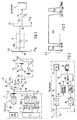
- the KTV head-end station 2 delivers a frequency multiplex signal with a bandwidth of 80 to 450 MHz, for example a frequency band for television and radio transmission similar to the coaxial KTV system BK 450 of the Deutsche Bundespost.
- this frequency division multiplex signal is not distributed to the subscribers as usual via coaxial lines, but rather via the optical message transmission system according to the invention.
- the frequency band which occupies the KTV frequency division multiplex signal is designated FB1, and therefore is also in Fig. 1, the line from the output of the KTV head station 2, which is a coaxial line, designated FB1.
- an electrical-optical converter 3 which converts it into an optical signal by using it for intensity modulation of its output light of wavelength ( ⁇ 1), preferably 1550 nm.
- an optical isolator 9 for protecting the transducer 3 from reflections of the optical signal to be transmitted downwards on any transmission devices, e.g. in the fiber optic amplifier 10.
- the optical output signal of the converter 3 is transmitted to a large number of subscribers, similar to the distribution system mentioned at the outset, via the optical waveguide network to be described, of which only one is represented and designated T i , and thereby by fiber-optic amplifiers 10 and 11 are located between successive branch points of the optical waveguide network.
- the subscriber-specific message signals to be transmitted from the control center 1 to the subscribers originate from a local exchange 4 located in the control center, to which the subscribers under consideration are connected via the optical fiber network.
- the number of subscribers connected to a local exchange is 1024.
- the local exchange 4 inputs the subscriber-specific signals to be transmitted to these subscribers via 1024 parallel output lines into a modulation device 5, which converts the large number of signals into a frequency division multiplex signal with subscriber-specific frequencies, 3 occupies a frequency band FB2, which ranges from approximately 470 to approximately 500 MHz.
- the frequency band FB2 contains 1024 carriers in one Frequency spacing of about 30 KHz apart and each of which is frequency modulated with one of the subscriber-specific message signals.
- the frequency division multiplex signal generated by the modulation device 5 with the frequency band FB2 arrives via an equally designated line in an electrical-optical converter 6, which converts it into an optical signal with the wavelength ⁇ 1, which is equal to the wavelength of the converter 3.
- This optical signal is transmitted to the subscribers T i via the optical waveguide network to be explained.
- the center 1 receives a mixture of optical signals with a single wavelength ⁇ 2, for example of 1300 nm, which contains up to 1024 electrical signals from a third frequency band FB3, which is from about 30 to 60 MHz (frequency plan according to FIG. 3) is enough.
- These electrical signals are subscriber-specific carriers, to which the subscriber-specific message signals to be transmitted from the subscribers T i to the central, as will be explained below, are modulated by frequency modulation.
- the carriers have carrier frequencies from the frequency band FB3 with frequency spacings of approximately 30 kHz.
- the received mixture of optical signals with the wavelength ⁇ 2 is converted in an optical-electrical converter 7 into an electrical frequency multiplex signal with the frequency band FB3 and entered via a line also designated in a demodulation device 8, which demodulates the signals contained therein and over 1024th enters parallel lines in the local exchange 4.
- a converter circuit is available which carries out the signal conversions required between the local exchange 4 and the modulating and demodulating devices 5 and 8, for example the conversion from two-wire to four-wire operation, and conversions of call, dialing and signaling signs.
- the mentioned connections of the center 1 for optical signals with the wavelength ⁇ 1 and the wavelength ⁇ 2 are connected to the fiber optic network as follows.
- the appearing at the outputs of the converters 3 and 6 of the central optical signals with the same wavelengths ⁇ 1 are combined by means of optical fiber connectors and optical fiber couplers 20 and 21 into a single optical signal, and the optical fiber coupler 21 distributes the result of the summary Signal on two optical fiber pieces 22 and 23, of which it is distributed by means of optical fiber couplers 24 and 25 to four optical fibers LA1 to LA4.
- the couplers 21, 24 and 25 are 3dB couplers, the coupler 20 is a wavelength selective coupler.
- the signals from the KTV system and the subscriber-specific signals are thus transmitted from the central station to subscribers via each of these optical fibers. In the following explanation, this transmission direction is referred to as the so-called downward direction and the opposite transmission direction as the so-called upward direction.
- the drawing shows representative of the fiber optic LA1 to LA4 the transmission over the fiber optic LA4.
- the optical waveguide LA4 leads from the coupler 25, which is a branching point of a star-star-shaped optical waveguide network, to a power divider 26, which is indicated only schematically, and which in turn is a branching point of the optical waveguide network, with a number of, for example, 16 further optical fibers LB1 to LB16.
- a power divider 26 which is indicated only schematically, and which in turn is a branching point of the optical waveguide network, with a number of, for example, 16 further optical fibers LB1 to LB16.
- an optical isolator 27 is inserted into the optical waveguide between the fiber-optic amplifier 10 and the power divider 26.
- the fiber optic amplifier 10 and the optical isolator 27 are part of an optical amplifier location A, which also includes means for amplifying the optical signals to be transmitted in the upward direction, if such means are required at this point in the optical fiber network.
- the couplers, power dividers and optical waveguides LA 1 to LA4 described so far, including the amplifier points A inserted into them, and the four power dividers 26 are preferably arranged locally close to the control center 1 or belong to the control center.
- an optical waveguide LB5 is shown, which, like all other not shown, leads to a further branching point of the optical waveguide network, a power divider 28.
- This distributes the optical signal transmitted in the downward direction to, for example, 16 further optical fibers LC 1 to LC 1, each of which leads to a subscriber, as shown for a representative optical waveguide LC 1 and a subscriber T i .
- the power dividers 26 and 28 are sometimes referred to below as couplers.
- an amplifier point B is inserted, which contains the above-mentioned fiber-optic amplifier 11 for amplifying the optical signal transmitted in the downward direction.
- An optical isolator for protecting the fiber optic amplifier 11 is not required in the part of the optical fiber network in which it is used, since the coupler 28 and the devices of the subscriber can be designed so that only very few reflections occur.
- the optical isolator 27 in the amplifier point A can also be omitted.
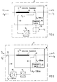
- the devices present at a subscriber T i which is representative of the large number of subscribers connected to the control center via the network described, will now be explained with reference to FIG. 2.
- the optical signal that the subscriber receives via the optical fiber that connects it to the node 28 is converted in an optical-to-electrical converter 30 into an electrical frequency multiplex signal, which shows the frequency bands FB 1 shown in FIG. 3 for the KTV signals and FB 2 for contains the individual subscriber signals.
- This frequency division multiplex signal is entered via an electrical coaxial line, referred to as KL, into the cable television house cabling which is usually present at a subscriber and is transmitted via this to one or more television receiving devices 31.
- a KTV band FB1 passing bandpass filter can be inserted, so that a standardized KTV signal is output at its output. Its output can then be viewed as a transfer point, ie as an interface between the responsibility of the network operator and that of the subscriber.
- the electrical output signal of the converter 30 is supplied to a demodulator 32 via a coaxial line.
- This is matched to the carrier frequency individually assigned to the subscriber, for example 500 MHz, so that the subscriber can extract the signal intended for him and only this from the total of subscriber-specific signals transmitted to subscribers via the network described.
- the signal intended for the subscriber for example a telephone signal
- appears in the baseband position which is input via a converter to a conventional terminal device, for example a telephone set.
- the subscriber To transmit a telephone or data signal from the subscriber to the control center, the subscriber has a modulator 35 which converts the signal entered by him from the output of the converter 33 to which the terminal 34 is connected into the frequency position individually assigned to the subscriber by using a specific one Carrier from the frequency band FB3, for example a carrier with 60 MHz, frequency modulated. Furthermore, he has an electrical-optical converter 36 for converting the electrical signal resulting from the modulation into an optical signal with a wavelength ⁇ 2 and an optical waveguide coupler 37, which the optical signal with the wavelength ⁇ 2 in between the coupler 28 and Coupling trending fiber optic cables.
- a modulator 35 which converts the signal entered by him from the output of the converter 33 to which the terminal 34 is connected into the frequency position individually assigned to the subscriber by using a specific one Carrier from the frequency band FB3, for example a carrier with 60 MHz, frequency modulated. Furthermore, he has an electrical-optical converter 36 for converting the electrical signal resulting from the modulation into an
- the coupler is a wavelength-selective coupler that couples light with the wavelength ⁇ 1 practically only to the input of the converter 30 and light with the wavelength ⁇ 2 from the output of the converter 36 only in the direction of the coupler 28 and practically not in the direction of the input of the converter 30.
- the wavelength ⁇ 2 is preferably 1300 nm, which is an advantageous value for the transmission to the control center, as will be explained below.
- the converter 33 takes care of the signal conversions required for the transmission of the signals from and to the standard terminal devices according to the invention, for example a two-wire-four-wire conversion and the Implementation of call, dialing and signaling signals so that its connection connected to the terminal 34 is to be regarded as an interface on which there are standard signals for the connected terminal.
- a subscriber can have as much telephone or data terminal equipment as can be individually allocated frequencies from the frequency bands FB2 and FB3, that is to say more than one telephone or data terminal, if more carrier frequencies can be provided in the said frequency bands than subscribers available.
- the same optical fiber network is used as for the downward signal transmission described above.
- the coupler 28 attenuates each of the optical signals to be transmitted in the upward direction since it basically attenuates the signals to be transmitted in the upward direction in accordance with its division ratio in the same way as the signals to be transmitted in the downward direction. Nevertheless, as calculations have shown, amplification of the optical signals in the upward direction is also not necessary between the coupler 28 and the coupler 26, but is only required after the optical signals have passed from the coupler 26 into the optical waveguide LA4. Therefore, in the place of the amplifier B, as the figure shows, there is no amplification of the signal to be transmitted in the upward direction provided, but only at the location of the amplifier A such means are available, which will be explained later. With larger divider ratios on the coupler 28, however, an amplification in the upward direction can also be provided at the location of the amplifier B as at the location of the amplifier A.
- the optical signals to be transmitted in the upward direction, all with the wavelength ⁇ 2 are fed via the couplers 25 (or 24), 21, and 20 to the converter 7 described above in the control center.
- a demodulation device 8 ensures that each subscriber-specific input line of the local exchange 4 is supplied with exactly the signal intended for it from the subscriber-specific signals.
- the wavelength ⁇ 2 of the optical signals to be transmitted in the upward direction is chosen so that it is favorable for the components of the system which have to pass through the signals.
- Optical signals with a wavelength of 1300 nm are practically not attenuated in a fiber-optic amplifier which is designed for 1550 nm and as is known today. Therefore and because at the wavelength of 1300 nm the standardized optical fibers have favorable transmission properties and for this wavelength also commercially available optical transmitters and receivers are available, ⁇ 2 is preferably chosen to be 1300 nm.
- an amplification of the optical signals to be transmitted in the upward direction is required.
- the optical amplification of the upward transmitted 1300 nm signals can e.g. by means as shown in Fig. 1. These means include a wavelength-selective optical waveguide coupler 40 which couples the 1300 ⁇ nm signal out of the optical waveguide LA ein, a fiber-optic amplifier 41 optimized for 1300 nm, the amplified output signal of which couples a second wavelength-selective coupler 42 into the optical waveguide LA4 for further transmission in the upward direction. If necessary, an optical isolator 43 may be provided between the latter and the output of the fiber optic amplifier 41 to protect the fiber optic amplifier from reflected signals. Instead of the fiber optic amplifier 41, an optical semiconductor amplifier can also be used.
- FIG. 4 shows an amplifier point A in a different configuration than that shown in FIG. 1.
- 4 contains a fiber optic amplifier 10 known per se, which, as usual, consists of an Er3+-doped fiber piece 50, a wavelength-selective fiber-optic coupler 51 and a pump light source 52.
- Coupler 51 such a wavelength-selective fiber optic is Coupler to use, which has the property of the optical signal coming from the input of the fiber optic amplifier 10 to its output with the wavelength ⁇ 1 as undamped as possible to output at its leading to the output of the fiber optic amplifier 10 coupler output and that of Pump light source 52 to produce pump light with the wavelength ⁇ p of 980 nm from its coupler input connected to it with as little loss as possible in the direction of the doped fiber piece 11.
- the optical signal to be transmitted in the upward direction with the wavelength ⁇ 2 (1300 nm) is now coupled out of the optical waveguide, amplified and transmitted further in the upward direction.
- the free connection of the coupler 51 in the known fiber optic amplifiers is used to decouple the optical signal transmitted in the upward direction with the wavelength ⁇ 2 from the optical waveguide. It is connected via an optical waveguide piece 53 to the input of an optical-electrical converter 54, which converts the optical signal into an electrical one.
- the electrical output signal of the converter 54 is now fed directly into the laser driver of the pump light source and thereby modulates the intensity of the light generated by the pump light source 52.
- the frequencies contained in the modulating electrical signal are, as explained above, in a frequency band between 30 and 60 MHz.
- the modulation of the pump light modulates the gain which the optical signal to be transmitted from the input of the fiber-optic amplifier to its output (in the downward direction) with the wavelength ⁇ 1 undergoes as it passes through the amplifying fiber piece 50.
- basically all frequencies are suitable as modulation frequencies which are much larger than the reciprocal of the service life of the energy states of the Er3 an material of the fiber piece 50 that can be excited by the pump light, i.e. frequencies above 1 MHz, and the frequency band FB3 is clearly above from that.
- the output signal of the converter 54 would have to be modulated onto an auxiliary carrier frequency using an auxiliary modulation device, which is indicated by dashed lines in FIG. 4 and is designated by the reference number 55, so that a modulation signal suitable for the pump light source is produced.
- the intensity of the pump light is so high that from the end of the fiber piece 50 distant from the coupler 51, a considerable portion, which is not absorbed in the fiber piece 50, reaches the optical waveguide which continues in the direction of the center and from there onwards to the center becomes.
- the optical signal to be transmitted in the upward direction is therefore not transmitted from the amplifier point A to the center as in FIG. 1 with the wavelength ⁇ 2, but with the wavelength ⁇ p .
- the pump light source first generates unmodulated light and the output signal of converter 54 is used to modulate the pump light in a modulator connected downstream of the pump light source. In this case too, the pump light generated by the pump light source is modulated.
- the above-described embodiment of the amplifier point A is an application of an invention which, in itself, is already the subject of an older German patent application P 40 36 327, the additional signal mentioned there to be transmitted by modulation of the pump light source by removal from the free end of the coupler 51 and optical-electrical conversion is provided.
- the required amplification of the signal to be transmitted in the upward direction in the present case is brought about by bringing the electrical output signal of the converter 54 to a level which is sufficiently high for modulating the pump light source and by the pump light being intense enough to be passed on to the center guarantee.
- the optical signal passes via an optical waveguide piece 58 to a wavelength-selective coupler 59, which couples it for further transmission in the upward direction into the optical waveguide leading from the amplifier point A towards the center (to the left in the drawing).
- This optical signal is amplified in comparison to the optical input signal of the converter 54, since the converter 54 typically also performs amplification functions.
- an optical amplifier point A of whatever design, which amplifies not only the signal transmitted in the downward direction but also the signal transmitted in the upward direction, can be inserted not only on the sections of the route shown in the exemplary embodiment according to FIG. 1, but on any one Sections of the entire system on which such "bidirectional" amplification is required.
- an optical amplifier point A of whatever design, which amplifies not only the signal transmitted in the downward direction but also the signal transmitted in the upward direction, can be inserted not only on the sections of the route shown in the exemplary embodiment according to FIG. 1, but on any one Sections of the entire system on which such "bidirectional" amplification is required.
- optical transmitter Only a single, expensive optical transmitter is required in the central office for this large number of subscribers, which optical transmitter must contain a highly linear and therefore expensive laser because of the large bandwidth of its electrical input signal (80 to 450 MHz).
- the number of optical waveguides LA1 to LA auf, to which branching takes place near or in the center does not have to be four, as shown in the exemplary embodiment.
- the number could also be another number, e.g. five, on the order of four.
- the modification lies in the fact that the frequencies individually allocated to the participants are not permanently allocated, as is described with reference to the exemplary embodiment according to FIG. 1 and FIG. 2, but that means are available for a participant to receive one of n frequencies from one band and assign one of n frequencies from the other frequency band, where n is significantly smaller than the number of participants.
- This allocation is done as needed ie a participant is only assigned one of the n frequencies if a connection between the participant and the central office is actually required for the purpose of bidirectional message transmission.
- a subscriber does not want to communicate with any other subscriber and is not called by a subscriber connected to the central office, none of the n frequencies is assigned to him, but is available to the other subscribers.
- the assignment is individual for each participant, because at a certain point in time a frequency, i.e. Channel is assigned to only one participant.
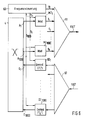
- the switching center 4 has output and input connections which are connected to modulators or demodulators.
- a separate modulator is available in the central office for each subscriber, and in FIG. 6 two modulators are representative of the modulators of the approximately 1000 subscribers connected to a switching center 4 MZ1 and MZ1000 shown.
- a power divider 62 is used to distribute the frequency division multiplex signal to the demodulators.
- each modulator and each demodulator can be set to one of n frequencies, where n is, for example, 100 if the number of participants is 1000.
- n is, for example, 100 if the number of participants is 1000.
- the frequency of the carrier to which a modulator modulates its input signal and the frequency of a carrier modulated with a signal that a demodulator can recover by demodulation is not fixed, but adjustable.
- a frequency control 63 present in the control center ensures that a frequency is assigned to a subscriber only when required and that the selected assignment is subscriber-specific, ie that the same frequency is never assigned to multiple subscribers at the same time.
- the frequencies are allocated to the modulators and the demodulators with the aid of the frequency control 63 as follows:
- the frequency control 63 is connected to each pair of modulators and demodulators available for a subscriber in the center via a data and control line.
- this line is denoted by S1 and in the case of the modulator-demodulator pair of subscriber No. 1000 by S1000.
- a bidirectional message transmission between a subscriber and the center can, as is typical for telephone traffic, either from the center, i.e. are initiated by the exchange 4, or by the subscriber.
- the exchange calls a subscriber or the subscriber sends a call signal to the exchange. In both cases it must be ensured that the frequencies are allocated for the communication link to be set up.
- the modulator MZ 1 recognizes that the state exists at the subscriber output A 1, which is typical for a call going from the switching center to a subscriber. If the output A 1 together with the input E 1 forms a subscriber line of an analog switching center, that is to say a classic connection for a subscriber line with an a, b wire, this is a specific current-voltage state the a, b core. If this is an S0 interface of an ISDN switching center, then this is the call signal state typically present on such an interface in the case of a call signal emanating from the exchange to a subscriber.
- the modulator MZ 1 determines that a call is to be sent from the switching center to subscriber No. 1 and signals this state to the frequency controller via the line S 1. This then searches for a free channel for the modulator MZ1. It does this by continuously querying the status of all modulators via the respective control and data lines, whether and at what frequency they are currently sending a message signal. On the basis of such a continuous query, the frequency controller stores which of n frequencies that can be assigned as a whole are currently unoccupied. If it finds an unoccupied frequency, it issues a control command corresponding to this frequency via the control line S 1 to the modulator MZ 1, which causes it to adjust to the frequency found. This frequency is designated f i in the exemplary embodiment according to FIG. 6. It is one of the n frequencies from a frequency band FB2 ', which will be explained later.
- two frequencies are allocated to a subscriber for the two transmission directions, which differ from one another by a predetermined amount. If, for example, the frequency controller selects a frequency f i of 960 MHz for transmission to subscriber no. 1, it also selects a frequency f i 'for the demodulator DZ 1 of the same subscriber, which is, for example, 60 MHz lower, in the example considered is 900 MHz.
- the frequency is allocated to the subscriber as follows:
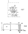
- Fig. 7 the part of a subscriber device T 1 of the system according to the invention required for the frequency allocation to the subscriber is shown.
- this subscriber device is regarded as that of subscriber no. 1 out of a number of 1000 subscribers connected to the central office.
- the subscriber device from FIG. 2 it has a modulator and a demodulator, but here the frequency can be adjusted. They are labeled MT1 and DT1.
- a frequency control 73 is used to set their frequencies.
- a call signal from the subscriber terminal that the subscriber device wants to send to the control center arrives at the input of the modulator MT 1, it also arrives directly or via the modulator to an input of the frequency control 73, in the example shown via a line 74.
- the frequency control 73 receives continuously from a frequency control channel on an input line 75, information about the current occupancy of the frequencies, which are continuously transmitted by the frequency control 6 of the control center to the entirety of the subscribers, by modulating a further carrier having a frequency f Frequenz with the information. From the reception of such information, the frequency controller has knowledge of free frequencies which are suitable for transmission from one subscriber to the control center, that is to say are not already assigned to a modulator of another subscriber.
- the frequency controller 73 causes the modulator MT 1 to adjust itself to this frequency, and at the same time also causes the demodulator DT 1 to adjust itself to a frequency different from the other frequency band by the above-mentioned fixed predetermined amount.
- the modulator MT1 modulates the call to the center on a carrier with a frequency f i ', sends to the center, and the demodulator DT1 is set to receive a signal with the carrier frequency f i .
- a demodulator of a subscriber on the central or on the subscriber side, determines that one of the scanned frequencies is modulated with a call signal that is specifically assigned to this subscriber, the frequency control that is present sets it at this frequency and sets it also set the modulator of the same modulator-demodulator pair to a frequency from the other frequency band that deviates from the frequency found by the fixed predetermined amount.
- the modulator MZ 1 has been set by the frequency controller 63 to a frequency f i (eg) for the purpose of a call signal to be sent out from the switch 4 to the subscriber T 1
- the demodulator DT 1 at the subscriber T 1 sets the call to him by scanning the frequencies the frequency f i , and the frequency control then sets it to this frequency f i and at the same time sets the modulator MT 1 to the frequency f i '(eg 900 MHz).
- the frequency control has already set the demodulator DZ 1 in the control center simultaneously with the frequency setting of the modulator MZ 1.
- the modulator MT 1 which was set to a free frequency f i '(for example 900 MHz) by the frequency controller 73 to send a call to the central, so the demodulator DZ 1 in the central determines by scanning all reception frequencies, that this frequency with a call signal from Participant T1 is modulated.
- the frequency control 63 connected to it ensures that the modulator MZ 1 is set to a frequency f i (for example 960 MHz) which is higher by a fixed amount.
- a modulator either in the central office or at the subscriber, determines from the state of its input line that the subscriber has changed to the end of the call or end of data transmission state, then it stops transmitting at the set carrier frequency and thus releases it .
- the frequency control ensures that the associated demodulator changes to the state of the sampling of the frequencies that are possible as receiving frequencies.
- the frequency control of the center queries the state of the modulators in order to find a free frequency for a modulator. Since the transmission and reception frequency of a modulator-demodulator pair of a subscriber are permanently assigned to one another, as explained, it is also possible for the frequency control in the center to have knowledge of free frequencies from the result of the continuous scanning of the frequency band provided for the demodulators the demodulators wins instead of continuously polling the status of the modulators. In a corresponding manner, it is possible for the participants that the frequency control system gains knowledge of free frequencies for demodulators from the continuous scanning of the frequency band provided for the demodulators, instead of evaluating the information received on the frequency control channel about the occupancy status of frequencies by the central office . In this case, it is generally not necessary to set up the frequency control channel.
- the demodulators output their message signal after recognizing a subscriber-specific one Release ring signal.
- subscriber-specific frequency controls can also be provided in the control center, as are explained for a subscriber with reference to FIG. 7, but then such that the scanning using the participant-specific demodulator instead of centrally determined and stored information.
- Another variant would be that there are not as many modulator-demodulator pairs as subscribers available on the central site, but only as many as frequency channels, in the example not 1000 but only 100, that the modulators and demodulators are set to fixed frequencies and there is a switching technology device between the normal switch 4 and the modulators, which connect the outputs of the normal switch to the inputs of currently free modulators and the outputs of the demodulators to inputs of the subscriber connections of the switch that are just being called. Even with such a configuration of the facilities available in the central office, it would be ensured that a pair of frequencies for the two transmission directions can be allocated to a subscriber as required and individually for each subscriber.
- a frequency band FB2 ' is provided for the transmission from the center to the subscribers, and a frequency band FB3' for the transmission in the opposite direction, wherein the former lies above the latter.
- FB3 ' ranges from 860 to 900 MHz
- FB2' ranges from 920 to 960 MHz. In this position, the frequency band FB1 can be significantly enlarged compared to that shown in FIG. 3, as indicated by FB1 '.
- variable frequency allocation described makes it possible to perform the frequency allocation flexibly in accordance with the bandwidth that is given for the subscriber line. If a subscriber connection is a connection for normal telephony, a smaller distance to such a narrowband channel can be provided in the channel allocation, whereas a larger channel distance can be set if it is a channel with a larger bandwidth, e.g. an ISDN channel or even a channel with an even wider bandwidth of e.g. 2 Mbit / s. Another advantage is that, because of the overall smaller number of channels required, bandwidth is saved for the frequency multiplex signal to be formed, which facilitates the optical transmission of the frequency multiplex signal.
Landscapes
- Engineering & Computer Science (AREA)
- Computer Networks & Wireless Communication (AREA)
- Signal Processing (AREA)
- Physics & Mathematics (AREA)
- Electromagnetism (AREA)
- Computing Systems (AREA)
- Optical Communication System (AREA)
- Two-Way Televisions, Distribution Of Moving Picture Or The Like (AREA)
Applications Claiming Priority (4)
| Application Number | Priority Date | Filing Date | Title |
|---|---|---|---|
| DE4104084 | 1991-02-11 | ||
| DE19914104084 DE4104084A1 (de) | 1991-02-11 | 1991-02-11 | Optisches nachrichtenuebertragungssystem fuer den teilnehmeranschlussbereich mit optischen verstaerkern |
| DE4116660 | 1991-05-22 | ||
| DE19914116660 DE4116660A1 (de) | 1991-05-22 | 1991-05-22 | Optisches nachrichtenuebertragungssystem fuer den teilnehmeranschlussbereich mit optischen verstaerkern |
Publications (3)
| Publication Number | Publication Date |
|---|---|
| EP0499065A2 true EP0499065A2 (fr) | 1992-08-19 |
| EP0499065A3 EP0499065A3 (en) | 1993-09-22 |
| EP0499065B1 EP0499065B1 (fr) | 1997-05-28 |
Family
ID=25900922
Family Applications (1)
| Application Number | Title | Priority Date | Filing Date |
|---|---|---|---|
| EP92101057A Expired - Lifetime EP0499065B1 (fr) | 1991-02-11 | 1992-01-23 | Système de transmission optique pour zone d'abonnés utilisant des amplificateurs optiques |
Country Status (9)
| Country | Link |
|---|---|
| US (1) | US5337175A (fr) |
| EP (1) | EP0499065B1 (fr) |
| JP (1) | JP3169665B2 (fr) |
| AT (1) | ATE153812T1 (fr) |
| AU (1) | AU649102B2 (fr) |
| CA (1) | CA2061041C (fr) |
| DE (1) | DE59208529D1 (fr) |
| ES (1) | ES2104740T3 (fr) |
| NZ (1) | NZ241581A (fr) |
Cited By (9)
| Publication number | Priority date | Publication date | Assignee | Title |
|---|---|---|---|---|
| EP0721261A1 (fr) * | 1995-01-09 | 1996-07-10 | AT&T Corp. | Réseaux optiques auto-amplifiés |
| WO1996031023A1 (fr) * | 1995-03-24 | 1996-10-03 | British Telecommunications Public Limited Company | Reseau optique |
| WO1996024989A3 (fr) * | 1995-02-06 | 1996-11-21 | Adc Telecommunications Inc | Systeme de telecommunications multipoint a point |
| EP0765045A1 (fr) * | 1995-09-21 | 1997-03-26 | ALCATEL BELL Naamloze Vennootschap | Dispositif de amplification et de combinaison de signaux optiques, et procédé de transmission amont utilisant un tel dispositif |
| AU703639B2 (en) * | 1995-02-06 | 1999-03-25 | Adc Telecommunications, Incorporated | Multi-point to point communication system |
| WO2001020819A1 (fr) * | 1999-09-14 | 2001-03-22 | Marconi Communications, Inc. | Dispositif et techniques permettant d'extraire deux bandes de frequence distinctes de la lumiere reçue par une photodiode |
| US6292651B1 (en) | 1995-02-06 | 2001-09-18 | Adc Telecommunications, Inc. | Communication system with multicarrier transport distribution network between a head end terminal and remote units |
| EP0954128A3 (fr) * | 1998-04-27 | 2004-01-28 | Delphi Technologies, Inc. | Réseau passif optique en forme d'étoile |
| US7058966B2 (en) | 1999-05-11 | 2006-06-06 | Tellabs Bedford, Inc. | Optical communication system for transmitting RF signals downstream and bidirectional telephony signals which also include RF control signals upstream |
Families Citing this family (38)
| Publication number | Priority date | Publication date | Assignee | Title |
|---|---|---|---|---|
| JPH0795161A (ja) * | 1993-09-20 | 1995-04-07 | Fujitsu Ltd | 光増幅中継伝送システム |
| US5504606A (en) * | 1994-06-01 | 1996-04-02 | At&T Corp. | Low power optical network unit |
| JPH0823309A (ja) * | 1994-07-08 | 1996-01-23 | Nec Corp | 双方向光catvシステムおよび双方向通信方法 |
| DE4438942A1 (de) * | 1994-10-31 | 1996-05-02 | Sel Alcatel Ag | Optisches Nachrichtenübertragungssystem für Kabelfernsehsignale und für teilnehmerindividuelle Signale |
| US7280564B1 (en) | 1995-02-06 | 2007-10-09 | Adc Telecommunications, Inc. | Synchronization techniques in multipoint-to-point communication using orthgonal frequency division multiplexing |
| USRE42236E1 (en) | 1995-02-06 | 2011-03-22 | Adc Telecommunications, Inc. | Multiuse subcarriers in multipoint-to-point communication using orthogonal frequency division multiplexing |
| DE19505578A1 (de) * | 1995-02-18 | 1996-08-22 | Sel Alcatel Ag | Optisches Übertragungssystem für Kabelfernsehsignale und Video- und Telekommunikationssignale |
| US5657153A (en) * | 1995-03-21 | 1997-08-12 | Sdl, Inc. | Optical amplifier with complementary modulation signal inputs |
| DE19511332A1 (de) * | 1995-03-28 | 1996-10-02 | Sel Alcatel Ag | Breitbandverteilsystem und Verfahren dazu |
| EP0873638B1 (fr) * | 1995-06-22 | 2010-08-04 | Scientific Atlanta, Inc. | Systeme hybride de telecommunications par fibres optiques et cables coaxiaux |
| US5861966A (en) * | 1995-12-27 | 1999-01-19 | Nynex Science & Technology, Inc. | Broad band optical fiber telecommunications network |
| US5867305A (en) * | 1996-01-19 | 1999-02-02 | Sdl, Inc. | Optical amplifier with high energy levels systems providing high peak powers |
| US5801858A (en) * | 1996-06-25 | 1998-09-01 | Northern Telecom Limited | Optical transmission systems using optical amplifiers and wavelength division multiplexing |
| DE19701888A1 (de) * | 1997-01-21 | 1998-07-23 | Alsthom Cge Alcatel | System zur optischen Übertragung von Informationen |
| US5912749A (en) * | 1997-02-11 | 1999-06-15 | Lucent Technologies Inc. | Call admission control in cellular networks |
| DE19737482A1 (de) | 1997-08-28 | 1999-03-04 | Alsthom Cge Alcatel | Verfahren zur optischen Übertragung über ein Lichtwellenleiternetz, sowie optisches Übertragungsnetz |
| KR100251692B1 (ko) * | 1997-09-12 | 2000-04-15 | 윤종용 | 광섬유 가입자 망 |
| FR2769139B1 (fr) * | 1997-09-29 | 1999-12-24 | Corning Inc | Appareil d'amplificateur optique |
| CN1255259A (zh) * | 1998-02-06 | 2000-05-31 | 富士通株式会社 | 光放大器,用于光放器中的激励光源控制方法,和光放大器控制方法 |
| EP1033835A3 (fr) * | 1999-03-03 | 2004-02-11 | Agilent Technologies, Inc. (a Delaware corporation) | Bureau central optique |
| US7103907B1 (en) | 1999-05-11 | 2006-09-05 | Tellabs Bedford, Inc. | RF return optical transmission |
| GB2361597A (en) * | 2000-04-20 | 2001-10-24 | Abb Offshore Systems Ltd | Underwater optical fibre communication system |
| WO2001099322A1 (fr) * | 2000-06-21 | 2001-12-27 | Mitsubishi Denki Kabushiki Kaisha | Système de transmission de données |
| US7352967B1 (en) | 2000-06-21 | 2008-04-01 | Mitsubishi Denki Kabushiki Kaisha | Data transmission system |
| JP4776835B2 (ja) * | 2001-09-20 | 2011-09-21 | シンクレイヤ株式会社 | 光ファイバネットワークシステムの伝送方式 |
| GB0206049D0 (en) * | 2002-03-14 | 2002-04-24 | Marconi Comm Ltd | Add/drop node for an optical communications network |
| JP4485355B2 (ja) * | 2002-05-30 | 2010-06-23 | 富士通株式会社 | 光信号を分配するシステム及び方法 |
| US7075712B2 (en) | 2002-05-30 | 2006-07-11 | Fujitsu Limited | Combining and distributing amplifiers for optical network and method |
| US7085496B2 (en) * | 2002-05-30 | 2006-08-01 | Fujitsu Limited | Passive add/drop amplifier for optical networks and method |
| KR20040026177A (ko) * | 2002-09-23 | 2004-03-30 | 삼성전자주식회사 | 방송 및 통신 신호를 수용할 수 있는 광가입자망 시스템 |
| JP2004120694A (ja) * | 2002-09-30 | 2004-04-15 | Synclayer Inc | 光伝送装置、中継装置及びそれを用いた光伝送システム |
| JP3880994B2 (ja) * | 2003-03-04 | 2007-02-14 | 富士通株式会社 | コンテンツ情報の配信方法並びに配信システムおよびそのセンタ局 |
| JP4411405B2 (ja) * | 2003-11-12 | 2010-02-10 | 株式会社創業 | リアルタイム放送システムとリアルタイム放送信号伝送方法 |
| KR20050070566A (ko) * | 2003-12-30 | 2005-07-07 | 삼성전자주식회사 | 다파장 광원과 그를 이용한 파장 분할 다중 시스템 |
| FR2872655A1 (fr) * | 2004-07-01 | 2006-01-06 | France Telecom | Reseau privatif multiservices et modules d'interface permettant de vehiculer, sur un tel reseau, des donnees sous differents formats |
| DE102006010147A1 (de) * | 2006-03-06 | 2007-09-13 | Siemens Ag | Bidirektionale optische Verstärkeranordnung |
| US7885543B2 (en) * | 2007-09-12 | 2011-02-08 | Verizon Patent And Licensing Inc. | High performance gigabit passive optical network |
| EP2834000A1 (fr) * | 2012-04-05 | 2015-02-11 | Corning Incorporated | Revêtement de polymère imperméable sur des surfaces choisies de canaux en nid d'abeilles |
Family Cites Families (20)
| Publication number | Priority date | Publication date | Assignee | Title |
|---|---|---|---|---|
| DE2922418C2 (de) * | 1979-06-01 | 1981-12-03 | Licentia Patent-Verwaltungs-Gmbh, 6000 Frankfurt | Dienstintegriertes Nachrichtenübertragungs- und Vermittlungssystem für Ton, Bild und Daten |
| DE3044657A1 (de) * | 1980-11-27 | 1982-07-08 | Licentia Patent-Verwaltungs-Gmbh, 6000 Frankfurt | "dienstintegriertes digitales uebertragungssystem" |
| DE3044702A1 (de) * | 1980-11-27 | 1982-06-24 | Licentia Patent-Verwaltungs-Gmbh, 6000 Frankfurt | Dienstintegriertes, digitales im zeitmultiplex arbeitendes uebertragungssystem |
| DE3045876A1 (de) * | 1980-12-05 | 1982-07-08 | Licentia Patent-Verwaltungs-Gmbh, 6000 Frankfurt | Dienstintegriertes, digitales uebertragungssystem |
| DE3045875A1 (de) * | 1980-12-05 | 1982-09-09 | Licentia Patent-Verwaltungs-Gmbh, 6000 Frankfurt | Dienstintegriertes, digitales uebertragungssystem |
| GB2155718B (en) * | 1984-03-08 | 1987-01-28 | Standard Telephones Cables Ltd | Local area network |
| DE3507064A1 (de) * | 1985-02-28 | 1986-08-28 | Standard Elektrik Lorenz Ag, 7000 Stuttgart | Optisches nachrichtenuebertragungssystem im teilnehmeranschlussbereich |
| US4705350A (en) * | 1985-09-19 | 1987-11-10 | Bell Communications Research, Inc. | Optical transmission network |
| EP0296201A1 (fr) * | 1987-01-05 | 1988-12-28 | BRITISH TELECOMMUNICATIONS public limited company | Reseau de transmission optique |
| US4809362A (en) * | 1987-03-13 | 1989-02-28 | Center For Innovative Technology | Fiber-optic star tree network |
| JPS6412830A (en) * | 1987-07-03 | 1989-01-17 | Fuji Electric Co Ltd | Uninterruptible power source |
| KR920000488B1 (ko) * | 1987-12-31 | 1992-01-14 | 고려화학 주식회사 | 분체도료용 히드록실 폴리에스테르 수지제조 방법 및 분체도료 조성물 |
| US4873681A (en) * | 1988-01-26 | 1989-10-10 | Bell Communications Research, Inc. | Hybrid optical and electronic packet switch |
| US4888380A (en) * | 1988-09-26 | 1989-12-19 | Dow Corning Corporation | Clear, non-slumping silicone sealants |
| US4891694A (en) * | 1988-11-21 | 1990-01-02 | Bell Communications Research, Inc. | Fiber optic cable television distribution system |
| DE3907495A1 (de) * | 1989-03-08 | 1990-09-13 | Standard Elektrik Lorenz Ag | Optisches nachrichtenuebertragungssystem fuer den teilnehmeranschlussbereich |
| US5083874A (en) * | 1989-04-14 | 1992-01-28 | Nippon Telegraph And Telephone Corporation | Optical repeater and optical network using the same |
| DE3913300A1 (de) * | 1989-04-22 | 1990-10-25 | Standard Elektrik Lorenz Ag | Optisches nachrichtenuebertragungssystem fuer den teilnehmeranschlussbereich |
| AT392555B (de) * | 1989-10-24 | 1991-04-25 | Alcatel Austria Ag | Verfahren zum uebertragen von binaerinformationen in einem optischen uebertragungsnetzwerk sowie optisches uebertragungsnetzwerk |
| US5212577A (en) * | 1990-01-19 | 1993-05-18 | Canon Kabushiki Kaisha | Optical communication equipment and optical communication method |
-
1992
- 1992-01-23 EP EP92101057A patent/EP0499065B1/fr not_active Expired - Lifetime
- 1992-01-23 AT AT92101057T patent/ATE153812T1/de not_active IP Right Cessation
- 1992-01-23 ES ES92101057T patent/ES2104740T3/es not_active Expired - Lifetime
- 1992-01-23 DE DE59208529T patent/DE59208529D1/de not_active Expired - Fee Related
- 1992-02-10 AU AU10874/92A patent/AU649102B2/en not_active Ceased
- 1992-02-11 CA CA002061041A patent/CA2061041C/fr not_active Expired - Fee Related
- 1992-02-11 NZ NZ241581A patent/NZ241581A/en unknown
- 1992-02-11 US US07/833,935 patent/US5337175A/en not_active Expired - Lifetime
- 1992-02-12 JP JP02545792A patent/JP3169665B2/ja not_active Expired - Fee Related
Non-Patent Citations (4)
| Title |
|---|
| ELECTRONICS LETTERS. Bd. 27, Nr. 1, 3. Januar 1991, STEVENAGE GB Seiten 89 - 91 SUYAMA ET AL 'Bidirectional transmission scheme using intensity modulation of 1.48um pump laser diode for erbium-doped fibre amplifier' * |
| FUNKSCHAU Nr. 3, 25. Januar 1991, MUNCHEN DE Seiten 59 - 62 MIKI 'Fibre to the Home: Strategien in Japan' * |
| IEEE GLOBAL TELECOMMUNICATIONS CONFERENCE November 1989, DALLAS, US Seiten 1671 - 1674 ROSHER ET AL 'A new approach to the provision of POTS and CATV over passive optical networks' * |
| IEEE TECHNICAL DIGEST ON OPTICAL AMPLIFIERS AND THEIR APPLICATIONS August 1990, MONTEREY, US Seiten 232 - 235 KIKUSHIMA ET AL 'Simultaneous distribution of AM/FM FDM TV signals to 65536 subscribers using 4 stage cascade EDFAs' * |
Cited By (25)
| Publication number | Priority date | Publication date | Assignee | Title |
|---|---|---|---|---|
| US8638655B2 (en) | 1994-09-26 | 2014-01-28 | Htc Corporation | Systems and method for orthogonal frequency divisional multiplexing |
| US8547824B2 (en) | 1994-09-26 | 2013-10-01 | Htc Corporation | Systems and methods for orthogonal frequency divisional multiplexing |
| EP0721261A1 (fr) * | 1995-01-09 | 1996-07-10 | AT&T Corp. | Réseaux optiques auto-amplifiés |
| US6606351B1 (en) | 1995-02-06 | 2003-08-12 | Adc Telecommunications, Inc. | Ingress protection in a communication system with orthogonal carriers |
| US6662367B2 (en) | 1995-02-06 | 2003-12-09 | Adc Telecommunications, Inc. | Poly-phase filters in multicarrier communication systems |
| AU703639B2 (en) * | 1995-02-06 | 1999-03-25 | Adc Telecommunications, Incorporated | Multi-point to point communication system |
| AU703284B2 (en) * | 1995-02-06 | 1999-03-25 | Htc Corporation | Multi-point to point communication system |
| AU703459B2 (en) * | 1995-02-06 | 1999-03-25 | Adc Telecommunications, Incorporated | Multi-point to point communication system |
| US8576693B2 (en) | 1995-02-06 | 2013-11-05 | Htc Corporation | Systems and method for orthogonal frequency division multiplexing |
| WO1996024989A3 (fr) * | 1995-02-06 | 1996-11-21 | Adc Telecommunications Inc | Systeme de telecommunications multipoint a point |
| US6594322B2 (en) | 1995-02-06 | 2003-07-15 | Adc Telecommunications, Inc. | Method of distributed loop control for a multicarrier telephony transport |
| US6292651B1 (en) | 1995-02-06 | 2001-09-18 | Adc Telecommunications, Inc. | Communication system with multicarrier transport distribution network between a head end terminal and remote units |
| US6535715B2 (en) | 1995-02-06 | 2003-03-18 | Adc Telecommunications, Inc. | Hybrid/fiber coax video and telephony communication system with poly-phase filtering |
| US6330241B1 (en) | 1995-02-06 | 2001-12-11 | Adc Telecommunications, Inc. | Multi-point to point communication system with remote unit burst identification |
| US6366585B1 (en) | 1995-02-06 | 2002-04-02 | Adc Telecommunications, Inc. | Distributed control in a communication system |
| US6477354B1 (en) | 1995-02-06 | 2002-11-05 | Adc Telecommunications, Inc. | Communication system transmitting modulated orthogonal carries with service units that scan spectrum to identify assigned band |
| CN1075298C (zh) * | 1995-03-24 | 2001-11-21 | 英国电讯有限公司 | 光学网络及其操作方法 |
| AU704526B2 (en) * | 1995-03-24 | 1999-04-29 | British Telecommunications Public Limited Company | Optical network |
| WO1996031023A1 (fr) * | 1995-03-24 | 1996-10-03 | British Telecommunications Public Limited Company | Reseau optique |
| EP0765045A1 (fr) * | 1995-09-21 | 1997-03-26 | ALCATEL BELL Naamloze Vennootschap | Dispositif de amplification et de combinaison de signaux optiques, et procédé de transmission amont utilisant un tel dispositif |
| US5754319A (en) * | 1995-09-21 | 1998-05-19 | Alcatel N.V. | Optical amplifier combiner arrangement and method for upstream transmission realized thereby |
| AU714781B2 (en) * | 1995-09-21 | 2000-01-13 | Alcatel N.V. | Optical amplifier splitter |
| EP0954128A3 (fr) * | 1998-04-27 | 2004-01-28 | Delphi Technologies, Inc. | Réseau passif optique en forme d'étoile |
| US7058966B2 (en) | 1999-05-11 | 2006-06-06 | Tellabs Bedford, Inc. | Optical communication system for transmitting RF signals downstream and bidirectional telephony signals which also include RF control signals upstream |
| WO2001020819A1 (fr) * | 1999-09-14 | 2001-03-22 | Marconi Communications, Inc. | Dispositif et techniques permettant d'extraire deux bandes de frequence distinctes de la lumiere reçue par une photodiode |
Also Published As
| Publication number | Publication date |
|---|---|
| AU649102B2 (en) | 1994-05-12 |
| EP0499065A3 (en) | 1993-09-22 |
| AU1087492A (en) | 1992-08-13 |
| ATE153812T1 (de) | 1997-06-15 |
| US5337175A (en) | 1994-08-09 |
| ES2104740T3 (es) | 1997-10-16 |
| CA2061041C (fr) | 1999-04-06 |
| EP0499065B1 (fr) | 1997-05-28 |
| JP3169665B2 (ja) | 2001-05-28 |
| DE59208529D1 (de) | 1997-07-03 |
| JPH0563659A (ja) | 1993-03-12 |
| CA2061041A1 (fr) | 1992-08-12 |
| NZ241581A (en) | 1995-02-24 |
Similar Documents
| Publication | Publication Date | Title |
|---|---|---|
| EP0499065B1 (fr) | Système de transmission optique pour zone d'abonnés utilisant des amplificateurs optiques | |
| DE2922418C2 (de) | Dienstintegriertes Nachrichtenübertragungs- und Vermittlungssystem für Ton, Bild und Daten | |
| EP0193190B1 (fr) | Système optique de transmission d'information dans la zone d'abonnement | |
| DE69123674T2 (de) | Mobiles Kommunikationssystem | |
| EP0727889B1 (fr) | Système de transmission optique pour signaux de télévision par câble et pour signaux de vidéo et télécommunication | |
| EP0151454B1 (fr) | Branchement d'abonné dans un système intégré à large bande | |
| EP0394728A2 (fr) | Système optique de transmission pour la zone de branchement d'abonné | |
| EP0386482B1 (fr) | Système de transmission optique pour connexion d'abonné | |
| EP0380945A2 (fr) | Système optique de transmission de communications à large bande, en particulier dans la région de branchement d'abonnés | |
| EP0386466B1 (fr) | Système optique de transmission d'information dans la zone d'abonné | |
| DE3632047C2 (de) | Optisches Nachrichtenübertragungssystem für Schmalband- und Breitband-Nachrichtensignale | |
| EP0972367B1 (fr) | Reseau d'acces pour la transmission de signaux optiques | |
| DE4226838B4 (de) | Optisches, breitbandiges Nachrichtenübertragungssystem für Kommunikations- und Verteildienste | |
| EP0881791B1 (fr) | Système de transmission optique d'informations | |
| DE69216435T2 (de) | Verfahren und Netzwerk zur Übertragung von Nachrichten über Frequenzkanäle | |
| DE69024119T2 (de) | Polarisationsregelung von bidirektional übertragenen Strahlenbündeln durch eine einzige Polarisationssteuerung | |
| EP0440081A2 (fr) | Système de radio mobile cellulaire | |
| EP0445364A2 (fr) | Système de communication optique | |
| EP0613315B1 (fr) | Dispositif et procédé pour la transmission de données par une ligne | |
| DE4116660A1 (de) | Optisches nachrichtenuebertragungssystem fuer den teilnehmeranschlussbereich mit optischen verstaerkern | |
| DE3422219A1 (de) | Optisches nachrichtenuebertragungssystem im teilnehmeranschlussbereich | |
| EP0760587A1 (fr) | Terminal radio utilisant un réseau hybride coax-fibre à large bande | |
| DE4104084A1 (de) | Optisches nachrichtenuebertragungssystem fuer den teilnehmeranschlussbereich mit optischen verstaerkern | |
| EP0162994A1 (fr) | Réseau de communication et son utilisation | |
| EP0386635B1 (fr) | Dispositif de répartition de signaux à large bande par un réseau ramifié de ligne coaxiale |
Legal Events
| Date | Code | Title | Description |
|---|---|---|---|
| PUAI | Public reference made under article 153(3) epc to a published international application that has entered the european phase |
Free format text: ORIGINAL CODE: 0009012 |
|
| AK | Designated contracting states |
Kind code of ref document: A2 Designated state(s): AT BE CH DE ES FR GB IT LI NL SE |
|
| RAP3 | Party data changed (applicant data changed or rights of an application transferred) |
Owner name: ALCATEL SEL AKTIENGESELLSCHAFT |
|
| PUAL | Search report despatched |
Free format text: ORIGINAL CODE: 0009013 |
|
| AK | Designated contracting states |
Kind code of ref document: A3 Designated state(s): AT BE CH DE ES FR GB IT LI NL SE |
|
| 17P | Request for examination filed |
Effective date: 19931119 |
|
| GRAG | Despatch of communication of intention to grant |
Free format text: ORIGINAL CODE: EPIDOS AGRA |
|
| 17Q | First examination report despatched |
Effective date: 19960614 |
|
| GRAH | Despatch of communication of intention to grant a patent |
Free format text: ORIGINAL CODE: EPIDOS IGRA |
|
| GRAH | Despatch of communication of intention to grant a patent |
Free format text: ORIGINAL CODE: EPIDOS IGRA |
|
| GRAA | (expected) grant |
Free format text: ORIGINAL CODE: 0009210 |
|
| AK | Designated contracting states |
Kind code of ref document: B1 Designated state(s): AT BE CH DE ES FR GB IT LI NL SE |
|
| REF | Corresponds to: |
Ref document number: 153812 Country of ref document: AT Date of ref document: 19970615 Kind code of ref document: T |
|
| REG | Reference to a national code |
Ref country code: CH Ref legal event code: EP Ref country code: CH Ref legal event code: NV Representative=s name: JUERG ULRICH C/O ALCATEL STR AG |
|
| RAP2 | Party data changed (patent owner data changed or rights of a patent transferred) |
Owner name: ALCATEL ALSTHOM COMPAGNIE GENERALE D'ELECTRICITE |
|
| REF | Corresponds to: |
Ref document number: 59208529 Country of ref document: DE Date of ref document: 19970703 |
|
| GBT | Gb: translation of ep patent filed (gb section 77(6)(a)/1977) |
Effective date: 19970714 |
|
| ET | Fr: translation filed | ||
| NLT2 | Nl: modifications (of names), taken from the european patent patent bulletin |
Owner name: ALCATEL ALSTHOM COMPAGNIE GENERALE D'ELECTRICITE |
|
| REG | Reference to a national code |
Ref country code: ES Ref legal event code: FG2A Ref document number: 2104740 Country of ref document: ES Kind code of ref document: T3 |
|
| REG | Reference to a national code |
Ref country code: CH Ref legal event code: NV Representative=s name: CABINET ROLAND NITHARDT CONSEILS EN PROPRIETE INDU |
|
| PLBE | No opposition filed within time limit |
Free format text: ORIGINAL CODE: 0009261 |
|
| STAA | Information on the status of an ep patent application or granted ep patent |
Free format text: STATUS: NO OPPOSITION FILED WITHIN TIME LIMIT |
|
| 26N | No opposition filed | ||
| REG | Reference to a national code |
Ref country code: CH Ref legal event code: PFA Free format text: ALCATEL ALSTHOM COMPAGNIE GENERALE D'ELECTRICITE TRANSFER- ALCATEL SOCIETE ANONYME |
|
| PGFP | Annual fee paid to national office [announced via postgrant information from national office to epo] |
Ref country code: CH Payment date: 20001214 Year of fee payment: 10 |
|
| PGFP | Annual fee paid to national office [announced via postgrant information from national office to epo] |
Ref country code: AT Payment date: 20001221 Year of fee payment: 10 |
|
| PGFP | Annual fee paid to national office [announced via postgrant information from national office to epo] |
Ref country code: NL Payment date: 20001222 Year of fee payment: 10 |
|
| PGFP | Annual fee paid to national office [announced via postgrant information from national office to epo] |
Ref country code: SE Payment date: 20001227 Year of fee payment: 10 |
|
| PGFP | Annual fee paid to national office [announced via postgrant information from national office to epo] |
Ref country code: BE Payment date: 20010118 Year of fee payment: 10 |
|
| PGFP | Annual fee paid to national office [announced via postgrant information from national office to epo] |
Ref country code: ES Payment date: 20010122 Year of fee payment: 10 |
|
| REG | Reference to a national code |
Ref country code: GB Ref legal event code: IF02 |
|
| PG25 | Lapsed in a contracting state [announced via postgrant information from national office to epo] |
Ref country code: AT Free format text: LAPSE BECAUSE OF NON-PAYMENT OF DUE FEES Effective date: 20020123 |
|
| PG25 | Lapsed in a contracting state [announced via postgrant information from national office to epo] |
Ref country code: ES Free format text: LAPSE BECAUSE OF NON-PAYMENT OF DUE FEES Effective date: 20020124 Ref country code: SE Free format text: LAPSE BECAUSE OF NON-PAYMENT OF DUE FEES Effective date: 20020124 |
|
| PG25 | Lapsed in a contracting state [announced via postgrant information from national office to epo] |
Ref country code: CH Free format text: LAPSE BECAUSE OF NON-PAYMENT OF DUE FEES Effective date: 20020131 Ref country code: LI Free format text: LAPSE BECAUSE OF NON-PAYMENT OF DUE FEES Effective date: 20020131 Ref country code: BE Free format text: LAPSE BECAUSE OF NON-PAYMENT OF DUE FEES Effective date: 20020131 |
|
| BERE | Be: lapsed |
Owner name: ALCATEL ALSTHOM CIE GENERALE D'ELECTRICITE Effective date: 20020131 |
|
| PG25 | Lapsed in a contracting state [announced via postgrant information from national office to epo] |
Ref country code: NL Free format text: LAPSE BECAUSE OF NON-PAYMENT OF DUE FEES Effective date: 20020801 |
|
| EUG | Se: european patent has lapsed |
Ref document number: 92101057.5 |
|
| REG | Reference to a national code |
Ref country code: CH Ref legal event code: PL |
|
| NLV4 | Nl: lapsed or anulled due to non-payment of the annual fee |
Effective date: 20020801 |
|
| REG | Reference to a national code |
Ref country code: ES Ref legal event code: FD2A Effective date: 20030922 |
|
| PGFP | Annual fee paid to national office [announced via postgrant information from national office to epo] |
Ref country code: DE Payment date: 20070110 Year of fee payment: 16 |
|
| PGFP | Annual fee paid to national office [announced via postgrant information from national office to epo] |
Ref country code: GB Payment date: 20070119 Year of fee payment: 16 |
|
| PGFP | Annual fee paid to national office [announced via postgrant information from national office to epo] |
Ref country code: IT Payment date: 20070626 Year of fee payment: 16 |
|
| PGFP | Annual fee paid to national office [announced via postgrant information from national office to epo] |
Ref country code: FR Payment date: 20070111 Year of fee payment: 16 |
|
| GBPC | Gb: european patent ceased through non-payment of renewal fee |
Effective date: 20080123 |
|
| PG25 | Lapsed in a contracting state [announced via postgrant information from national office to epo] |
Ref country code: DE Free format text: LAPSE BECAUSE OF NON-PAYMENT OF DUE FEES Effective date: 20080801 |
|
| REG | Reference to a national code |
Ref country code: FR Ref legal event code: ST Effective date: 20081029 |
|
| PG25 | Lapsed in a contracting state [announced via postgrant information from national office to epo] |
Ref country code: GB Free format text: LAPSE BECAUSE OF NON-PAYMENT OF DUE FEES Effective date: 20080123 |
|
| PG25 | Lapsed in a contracting state [announced via postgrant information from national office to epo] |
Ref country code: FR Free format text: LAPSE BECAUSE OF NON-PAYMENT OF DUE FEES Effective date: 20080131 |
|
| PG25 | Lapsed in a contracting state [announced via postgrant information from national office to epo] |
Ref country code: IT Free format text: LAPSE BECAUSE OF NON-PAYMENT OF DUE FEES Effective date: 20080123 |