EP0499257B1 - Wärmeaustauschrohr kleiner Abmessungen und Verfahren zu dessen Herstellung - Google Patents
Wärmeaustauschrohr kleiner Abmessungen und Verfahren zu dessen Herstellung Download PDFInfo
- Publication number
- EP0499257B1 EP0499257B1 EP92102423A EP92102423A EP0499257B1 EP 0499257 B1 EP0499257 B1 EP 0499257B1 EP 92102423 A EP92102423 A EP 92102423A EP 92102423 A EP92102423 A EP 92102423A EP 0499257 B1 EP0499257 B1 EP 0499257B1
- Authority
- EP
- European Patent Office
- Prior art keywords
- tube
- heat
- small size
- transfer
- groove
- Prior art date
- Legal status (The legal status is an assumption and is not a legal conclusion. Google has not performed a legal analysis and makes no representation as to the accuracy of the status listed.)
- Expired - Lifetime
Links
Images





Classifications
-
- B—PERFORMING OPERATIONS; TRANSPORTING
- B21—MECHANICAL METAL-WORKING WITHOUT ESSENTIALLY REMOVING MATERIAL; PUNCHING METAL
- B21D—WORKING OR PROCESSING OF SHEET METAL OR METAL TUBES, RODS OR PROFILES WITHOUT ESSENTIALLY REMOVING MATERIAL; PUNCHING METAL
- B21D39/00—Application of procedures in order to connect objects or parts, e.g. coating with sheet metal otherwise than by plating; Tube expanders
-
- F—MECHANICAL ENGINEERING; LIGHTING; HEATING; WEAPONS; BLASTING
- F28—HEAT EXCHANGE IN GENERAL
- F28F—DETAILS OF HEAT-EXCHANGE AND HEAT-TRANSFER APPARATUS, OF GENERAL APPLICATION
- F28F1/00—Tubular elements; Assemblies of tubular elements
- F28F1/10—Tubular elements and assemblies thereof with means for increasing heat-transfer area, e.g. with fins, with projections, with recesses
- F28F1/40—Tubular elements and assemblies thereof with means for increasing heat-transfer area, e.g. with fins, with projections, with recesses the means being only inside the tubular element
-
- B—PERFORMING OPERATIONS; TRANSPORTING
- B21—MECHANICAL METAL-WORKING WITHOUT ESSENTIALLY REMOVING MATERIAL; PUNCHING METAL
- B21C—MANUFACTURE OF METAL SHEETS, WIRE, RODS, TUBES, PROFILES OR LIKE SEMI-MANUFACTURED PRODUCTS OTHERWISE THAN BY ROLLING; AUXILIARY OPERATIONS USED IN CONNECTION WITH METAL-WORKING WITHOUT ESSENTIALLY REMOVING MATERIAL
- B21C37/00—Manufacture of metal sheets, rods, wire, tubes, profiles or like semi-manufactured products, not otherwise provided for; Manufacture of tubes of special shape
- B21C37/06—Manufacture of metal sheets, rods, wire, tubes, profiles or like semi-manufactured products, not otherwise provided for; Manufacture of tubes of special shape of tubes or metal hoses; Combined procedures for making tubes, e.g. for making multi-wall tubes
- B21C37/15—Making tubes of special shape; Making tube fittings
- B21C37/20—Making helical or similar guides in or on tubes without removing material, e.g. by drawing same over mandrels, by pushing same through dies ; Making tubes with angled walls, ribbed tubes or tubes with decorated walls
- B21C37/207—Making helical or similar guides in or on tubes without removing material, e.g. by drawing same over mandrels, by pushing same through dies ; Making tubes with angled walls, ribbed tubes or tubes with decorated walls with helical guides
-
- Y—GENERAL TAGGING OF NEW TECHNOLOGICAL DEVELOPMENTS; GENERAL TAGGING OF CROSS-SECTIONAL TECHNOLOGIES SPANNING OVER SEVERAL SECTIONS OF THE IPC; TECHNICAL SUBJECTS COVERED BY FORMER USPC CROSS-REFERENCE ART COLLECTIONS [XRACs] AND DIGESTS
- Y10—TECHNICAL SUBJECTS COVERED BY FORMER USPC
- Y10T—TECHNICAL SUBJECTS COVERED BY FORMER US CLASSIFICATION
- Y10T29/00—Metal working
- Y10T29/49—Method of mechanical manufacture
- Y10T29/4935—Heat exchanger or boiler making
-
- Y—GENERAL TAGGING OF NEW TECHNOLOGICAL DEVELOPMENTS; GENERAL TAGGING OF CROSS-SECTIONAL TECHNOLOGIES SPANNING OVER SEVERAL SECTIONS OF THE IPC; TECHNICAL SUBJECTS COVERED BY FORMER USPC CROSS-REFERENCE ART COLLECTIONS [XRACs] AND DIGESTS
- Y10—TECHNICAL SUBJECTS COVERED BY FORMER USPC
- Y10T—TECHNICAL SUBJECTS COVERED BY FORMER US CLASSIFICATION
- Y10T29/00—Metal working
- Y10T29/49—Method of mechanical manufacture
- Y10T29/4935—Heat exchanger or boiler making
- Y10T29/49377—Tube with heat transfer means
- Y10T29/49378—Finned tube
- Y10T29/49385—Made from unitary workpiece, i.e., no assembly
-
- Y—GENERAL TAGGING OF NEW TECHNOLOGICAL DEVELOPMENTS; GENERAL TAGGING OF CROSS-SECTIONAL TECHNOLOGIES SPANNING OVER SEVERAL SECTIONS OF THE IPC; TECHNICAL SUBJECTS COVERED BY FORMER USPC CROSS-REFERENCE ART COLLECTIONS [XRACs] AND DIGESTS
- Y10—TECHNICAL SUBJECTS COVERED BY FORMER USPC
- Y10T—TECHNICAL SUBJECTS COVERED BY FORMER US CLASSIFICATION
- Y10T29/00—Metal working
- Y10T29/49—Method of mechanical manufacture
- Y10T29/4935—Heat exchanger or boiler making
- Y10T29/49391—Tube making or reforming
Definitions
- the present invention relates to a heat-transfer small size tube used for a heat exchanger in a refrigerator, an air conditioner, or the like, and a method of manufacturing the same.
- cross fin type heat exchangers are most frequently used.
- This cross fin type heat exchanger is manufactured in the following manner. Heat-transfer tubes are inserted in aluminum fins having louvers or the like formed in its surface to exchange heat with air, and a through hole formed therein to allow the heat-transfer tube to be inserted. Expansion plugs are then inserted into the heat-transfer tubes to expand the tubes, thus causing the outer surface of the heat-transfer tube to come into contact with the aluminum fin. The resulting structure is assembled in the main body of the heat exchanger, thus completing the manufacturing process.
- refrigerant such as Freon is fed into the heat-transfer tube.
- a heat-transfer small size tube comprising a metal tube having an outer diameter of 3 to 6 mm, and grooves continuously formed, in an inner surface of the metal tube, in a spiral shape or in a tube-axis direction, each of the grooves having a groove depth H defined by 0.15 ⁇ H ⁇ 0.25 mm, and a groove bottom width W1 defined by 0.10 ⁇ W1 ⁇ 0.20 mm, wherein a ratio t/D of a bottom wall thickness of the metal tube to the outer diameter of the metal tube is 0.025 ⁇ t/D ⁇ 0.075.
- This object can be achieved by a method of manufacturing a heat-transfer small size tube, comprising the steps of inserting a grooved plug in a metal tube having an outer diameter of not less than 4.5 mm, performing a rotary or drawing process with respect to an outer surface of the metal tube while pulling the metal tube in a tube-axis direction, thereby continuously forming grooves, in an inner surface of the metal tube, in a spiral shape or in the tube-axis direction, each of the grooves having a ridge bottom width/bottom wall thickness ratio W2/t defined as 0.2 to 1.5, a groove depth H defined as 0.15 to 0.30 mm, and a groove bottom width W1 defined as 0.15 to 0.50 mm, and subjecting to diameter reduction process with a diameter reduction rate of 20 to 40% by performing at least one draw without plug process with respect to the metal tube to obtain a heat-transfer small size tube having a groove depth H defined by 0.15 ⁇ H ⁇ 0.25 mm, a groove bottom width W1 defined by 0.10 ⁇ W1 ⁇
- An outer diameter D of a heat-transfer small size tube of the present invention is set to be 3 to 6 mm for the following reasons. If the outer diameter D is less than 3 mm, it is difficult to form grooves having predetermined shapes. In contrast to this, the outer diameter D exceeding 6 mm makes no contribution to a reduction in size of a heat exchanger.
- a groove depth H is set to be 0.15 ⁇ H ⁇ 0.25 mm; and a groove bottom width W1, 0.10 to 0.20 mm to optimize the heat transfer performance while ensuring substantially the same workability and cost as those of a conventional inner grooved tube.
- a bottom wall thickness t in relation to the tube outer diameter D is set to satisfy 0.025 ⁇ t/D ⁇ 0.075 in order to minimize a decrease in heat transfer performance due to deformation of grooves.
- a apex angle ⁇ of a ridge is preferably set to be 20° ⁇ ⁇ ⁇ 50°.
- a ratio W2/t of the ridge bottom width to the bottom wall thickness is limited to 0.2 to 1.5 for the following reasons. If the ratio W2/t is less than 0.2, a grooving process cannot be performed because the ridge bottom width is too small with respect to the bottom wall thickness set in a normal manufacturing process. If the ratio W2/t exceeds 1.5, the bottom wall thickness is excessively reduced as compared with the ridge bottom width so that depressions are formed in the outer surface of the tube or split defects on the metal surface or the like are often caused in a diameter reducing process with a diameter reduction rate of 20 to 40% after a grooving process.
- a constant force acts in the circumferential direction.
- the circumferential force per unit area varies.
- the wall thickness increase ratio in the diameter reducing process slightly varies. If the groove shape of a processed tube is such that the ridge bottom width is large as compared with the bottom wall thickness, depressions 2 are formed in an outer surface portion corresponding to a ridge 4, or split defects 3 on the metal surface extend into the tube wall, as shown in Figs. 1 and 2.
- the diameter reduction rate after the grooving process is set to be 40% or less in order to suppress such defects to such an extent that no problems are posed in terms of manufacture.
- a diameter reduction rate of less than 20% results in loss of an advantageous feature in the diameter reducing process of a small size tube having a small manufacture weight per unit time, i.e., the feature that the manufacture weight is increased by reducing the diameter of the small size tube after the formation of grooves.
- the outer diameter of a metal tube is set to be 4.5 mm or more for the following reason. If the outer diameter is less than 4.5 mm, the pulling force required for a grooving process exceeds the breaking load of the tube, thus hindering the grooving process.
- each groove formed in the inner surface of the metal tube is limited to 0.15 to 0.30 mm to set a finished groove depth of 0.15 ⁇ H ⁇ 0.25 mm, in consideration of the fact that the reduction ratio in the process of reducing the diameter to 20 to 40% is 1.05 to 1.2.
- the groove bottom width of each groove formed in the inner surface of the metal tube is set to be 0.15 to 0.50 mm to set a finished groove width of 0.10 ⁇ W1 ⁇ 0.20 mm, in consideration of the fact that the reduction ratio in a diameter reducing process with a diameter reduction rate of 20 to 40% is 0.7 to 0.4.
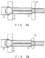
- Figs. 3A and 3B respectively show rotary units used in the manufacture of the heat-transfer small size tube of the present invention.
- a floating plug 31 is inserted in a metal tube 30, and a floating die 32 is arranged to draw the metal tube 30.
- a grooved plug 33 is held in the metal tube 30 at a predetermined position by the floating plug 31.
- Rotary rollers 34 are arranged outside the grooved plug 33.
- the arrangement of the rotary unit shown in Fig. 3B is the same as that of the rotary unit shown in Fig. 3A except that rotary balls 35 are used in place of the rotary rollers 34.
- ⁇ denotes a lead angle.
- a rotary process was performed with respect to a phosphrous deoxidized copper tube.
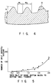
- various types of inner grooved tubes having the cross-sectional shape shown in Fig. 4 and a length of about 1,000 m were manufactured.
- Each tube had a groove depth of 0.1 to 0.3 mm, a bottom wall thickness of 0.2 to 0.35 mm, and a ridge bottom width/bottom wall thickness ratio W2/t of 0.2 to 2.0.
- W1 denotes a groove bottom width
- ⁇ an apex angle of a ridge.
- a diameter reducing process with a reduction rate of 38% was performed with respect to each tube to manufacture a heat-transfer small size tube having an outer diameter of 4 mm and a groove depth of 0.09 to 0.25 mm.
- Fig. 5 shows the result. Note that a grooving process could not performed when the ratio W2/t was less than 0.2. As is apparent from Fig. 5, when the ratio W2/t exceeds 1.5, the number of split defects increases abruptly. For this reason, it is required that the ratio W2/t of the ridge bottom width to the bottom wall thickness be 0.2 to 1.5.
- a rotary process was performed with respect to a tube having an outer diameter of 5.5 to 9.53 mm by using a grooved plug having an outer diameter of 4.5 to 7.5 mm, thus manufacturing inner grooved tubes with various sizes.
- a diameter reducing process with a diameter reduction rate of 20 to 40% was performed with respect to each inner grooved tube by performing at least one draw without plug process, thus manufacturing a heat-transfer small size tube having an outer diameter of 3 to 6 mm.
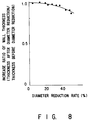
- 6 to 8 respectively show the relationship between the diameter reduction ratio and the width reduction ratios of the groove bottom width and the ridge bottom width before and after the diameter reducing process (width after diameter reducing process/width before diameter reducing process), the relationship between the reduction rate and the reduction ratio of the groove depth before and after the diameter reducing process (depth after diameter reducing process/depth before diameter reducing process), and the relationship between the reduction rate and the increase ratio of the wall thickness before and after the diameter reducing process (thickness after diameter reducing process/thickness before diameter reducing process).
- the reduction ratios of the groove bottom width and the ridge bottom width are decreased as the reduction rate is increased.
- the reduction ratio of the groove depth is increased as the reduction rate is increased.
- the wall thickness increase ratio is decreased as the reduction rate is increased.
- each tube had an outer diameter of 6.5 mm, a groove depth of 0.1 to 0.22 mm, a bottom wall thickness of 0.22 to 0.29, and a groove bottom width W1 of 0.125 to 0.625 mm.
- a diameter reducing process with a diameter reduction rate of 38% was performed with respect to each inner grooved tube by sinking process, thereby manufacturing a heat-transfer small size tube having an outer diameter of 4 mm, a groove depth of 0.09 to 0.19 mm, a bottom wall thickness of 0.23 to 0.30 mm, and a groove bottom width of 0.05 to 0.25 mm.
- Table 1 shows the sizes of some representative heat-transfer small size tubes.
- Table 1 No. Outer Diameter D (mm) Minimum Inner Diameter (mm) Number of Grooves Lead Angle (°) ⁇ Groove Depth H (mm) Groove Bottom Width W1 (mm) 1 4.00 3.14 50 2 0.15 0.05 2 4.00 3.16 50 8 0.15 0.06 3 4.00 3.24 50 19 0.09 0.07 4 4.00 3.16 40 8 0.15 0.12 5 4.00 3.14 36 8 0.14 0.15 6 4.00 3.16 36 8 0.19 0.15 7 4.00 3.40 - - - -
- the performance of inside heat transfer coefficient of each heat-transfer small size tube was evaluated. Note that the performance of inside heat transfer coefficient of each tube was measured in the following manner. Each heat-transfer small size tube was assembled in a double tube type heat exchanger, and Freon R-22 was circulated inside the heat-transfer tube, while coolant or cooling water was flown outside the tube. Under the measurement conditions shown in Tables 2 and 3 below, the inside heat transfer coefficient and the inside pressure drop in evaporation or condensation were measured.
- Figs. 9 and 10 respectively show the relationship between the flow rate of the refrigerant and the inside pressure drop in evaporation and that in condensation.
- the inside pressure drop in the heat-transfer small size tube of the present invention is 1.8 times that in a smooth tube.
- there is almost no difference in pressure drop based on the difference in groove shape, e.g., groove depth.
- the inside pressure drop in the heat-transfer small size tube of the present invention is 1.4 times that of the smooth tube.
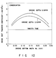
- Figs. 11 and 12 respectively show the relationship between the groove bottom width W1 and the inside heat transfer coefficient in evaporation and that in condensation.
- the flow rate of the refrigerant is set to be 400 kg/m2s.
- each groove is always filled with a liquid, and hence the inside heat transfer performance is degraded. That is, the optimal values of the circumferential length of the inner surface of the heat-transfer tube and the liquid film amount in each groove exist near 0.1 to 0.20 mm.
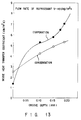
- Fig. 13 shows the maximum value of inside heat transfer performance with respect to each groove depth obtained from Figs. 11 and 12.
- the inside heat transfer coefficient is increased substantially in proportion to the groove depth.
- the inside heat transfer performance of the heat-transfer small size tube of the present invention is at least twice that of a smooth tube. Therefore, it is required that the groove depth be set to be H > 0.15 mm.
- the groove bottom width must be set to be 0.10 ⁇ W1 ⁇ 0.20 mm, as is apparent from Figs. 11 and 12. With this setting, the inside heat transfer performance nearly twice that of a smooth tube can be obtained in condensation. Furthermore, in evaporation, a remarkable improvement in inside heat transfer performance can be expected as compared with the case wherein H ⁇ 0.15 mm.
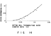
- Fig. 14 shows the relationship between a groove deformation amount ⁇ h (the difference between groove depths before and after the expansion of the tube) and a ratio t/D of the bottom wall thickness to the outer diameter.
- ⁇ h the difference between groove depths before and after the expansion of the tube
- t/D the ratio of the bottom wall thickness to the outer diameter.
- Fig. 15 shows the inside heat transfer coefficient in evaporation, as the result, with respect to the groove deformation amount ⁇ h.
- Fig. 15 shows the maximum inside heat transfer performance of a heat-transfer small size tube having the same groove depth as the groove depth after the tube expansion process, obtained from Figs. 11 and 12.
- ⁇ h ⁇ 0.04 the inside heat transfer performance after the tube expansion process is deteriorated in accordance with a decrease in groove depth.
- each ridge deforms greatly to have a substantially trapedoizal cross-sectional shape, and the degradation in inside heat transfer performance becomes greater than that due to the influence of the decrease in groove depth. That is, the inside heat transfer performance of such a tube having deformed grooves is much lower than the performance obtained with a tube with grooves each having the same groove depth but an optimal shape.
- the performance of inside heat transfer coefficient can be greatly improved.
- the degradation in performance due to the deformation of grooves can be minimized. This makes it possible to manufacture a compact heat exchanger which is much smaller and more efficient than a conventional heat exchanger.
- a heat-transfer tube having high heat transfer performance specifically a heat-transfer small tube, can be efficiently manufactured while the formation of depressions and split defects on the metal surface is suppressed.
Landscapes
- Engineering & Computer Science (AREA)
- Mechanical Engineering (AREA)
- Physics & Mathematics (AREA)
- Geometry (AREA)
- Thermal Sciences (AREA)
- General Engineering & Computer Science (AREA)
- Metal Extraction Processes (AREA)
- Rigid Pipes And Flexible Pipes (AREA)
Claims (5)
- Wärmeübertragungsröhre mit kleinen Abmessungen, mit einer Metallröhre mit einem äußeren Durchmesser von 3 bis 6 mm, und fortlaufend in einer inneren Oberfläche der Metallröhre gebildeten Rillen, in einer Spirale (Gestalt) oder in einer Röhrenachsenrichtung, wobei jede der Rillen eine Rillentiefe H, definiert durch 0,15 < H < 0,25 mm hat, und eine Rillenbodenbreite W₁ definiert durch 0,10 ≦ W₁ ≦ 0,20 mm, worin ein Verhältnis t/D einer Bodenwanddicke der Metallröhre zu dem äußeren Durchmesser der Metallröhre 0,025 ≦ t/D ≦ 0,075 ist.
- Wärmeübertragungsröhre mit kleinen Abmessungen gemäß Anspruch 1, dadurch gekennzeichnet, daß der Scheitelwinkel im Querschnitt einer sich zwischen den jeweiligen Rillen befindlichen Rippe in Grad im Bereich von 20 bis 50 liegt.
- Wärmeübertragungsröhre mit kleinen Abmessungen nach Anspruch 1, dadurch gekennzeichnet, daß die Röhre mit kleinen Abmessungen den Führungswinkel der Rillen zu einer Achse der Röhre von weniger als 20° aufweist.
- Wärmeübertragungsröhre mit kleinen Abmessungen nach Anspruch 1, dadurch gekennzeichnet, daß die kleine Röhre aus Kupfer besteht.
- Verfahren zum Herstellen einer Wärmeübertragungsröhre mit kleinen Abmessungen, mit den Schritten Einsetzen eines gerillten Stopfens in eine Metallröhre mit einem äußeren Durchmesser von nicht weniger als 4,5 mm, Durchführen eines Dreh- oder Ziehprozesses bezüglich einer äußeren Oberfläche der Metallröhre, während die Metallröhre in einer Röhrenachsenrichtung gezogen wird, wodurch fortlaufend Rillen gebildet werden, in einer inneren Oberfläche der Metallröhre, in einer Spiralgestalt oder in der Röhrenachsenrichtung, wobei jede der Rillen ein Rippenbodenbreiten/Bodenwanddicken-Verhältnis W₂/t, definiert als 0,2 bis 1,5, aufweist, eine Rillentiefe H, definiert als 0,15 bis 0,30 mm, und eine Rillenbodenbreite W₁, definiert als 0,15 bis 0,50 mm, und Durchführen eines Durchmesserreduktionsprozesses mit einer Durchmesserreduktionsrate von 20 bis 40% mittels Durchführen von wenigstens einem Ziehprozeß ohne Stopfen bezüglich der Metallröhre, um eine Wärmeübertragungsröhre mit kleinen Abmessungen mit einer Rillentiefe H, definiert durch 0,15 < H < 0,25 mm, einer Rillenbodenbreite W₁, definiert durch 0,10 ≦ W₁ ≦ 0,20 mm, und einem Verhältnis t/D der Bodenwanddicke der Metallröhre zum äußeren Durchmesser der Metallröhre, definiert durch 0,025 ≦ t/D ≦ 0,075, zu erhalten.
Applications Claiming Priority (4)
| Application Number | Priority Date | Filing Date | Title |
|---|---|---|---|
| JP41068/91 | 1991-02-13 | ||
| JP3041068A JPH04260792A (ja) | 1991-02-13 | 1991-02-13 | 細径伝熱管 |
| JP48946/91 | 1991-02-21 | ||
| JP3048946A JP2756192B2 (ja) | 1991-02-21 | 1991-02-21 | 伝熱管の製造法 |
Publications (3)
| Publication Number | Publication Date |
|---|---|
| EP0499257A2 EP0499257A2 (de) | 1992-08-19 |
| EP0499257A3 EP0499257A3 (en) | 1993-03-10 |
| EP0499257B1 true EP0499257B1 (de) | 1994-12-28 |
Family
ID=26380603
Family Applications (1)
| Application Number | Title | Priority Date | Filing Date |
|---|---|---|---|
| EP92102423A Expired - Lifetime EP0499257B1 (de) | 1991-02-13 | 1992-02-13 | Wärmeaustauschrohr kleiner Abmessungen und Verfahren zu dessen Herstellung |
Country Status (6)
| Country | Link |
|---|---|
| US (1) | US5555622A (de) |
| EP (1) | EP0499257B1 (de) |
| KR (1) | KR950007759B1 (de) |
| CN (1) | CN1062951C (de) |
| DE (1) | DE69200970T2 (de) |
| MY (1) | MY110330A (de) |
Families Citing this family (30)
| Publication number | Priority date | Publication date | Assignee | Title |
|---|---|---|---|---|
| US5070937A (en) * | 1991-02-21 | 1991-12-10 | American Standard Inc. | Internally enhanced heat transfer tube |
| US6935409B1 (en) * | 1998-06-08 | 2005-08-30 | Thermotek, Inc. | Cooling apparatus having low profile extrusion |
| US7147045B2 (en) * | 1998-06-08 | 2006-12-12 | Thermotek, Inc. | Toroidal low-profile extrusion cooling system and method thereof |
| US6981322B2 (en) | 1999-06-08 | 2006-01-03 | Thermotek, Inc. | Cooling apparatus having low profile extrusion and method of manufacture therefor |
| US7305843B2 (en) | 1999-06-08 | 2007-12-11 | Thermotek, Inc. | Heat pipe connection system and method |
| JP2001241877A (ja) * | 2000-02-25 | 2001-09-07 | Furukawa Electric Co Ltd:The | 内面溝付管及びその製造方法 |
| KR100382341B1 (ko) * | 2000-07-06 | 2003-05-01 | 엘지전자 주식회사 | 세경관형 열교환기 |
| US6462949B1 (en) | 2000-08-07 | 2002-10-08 | Thermotek, Inc. | Electronic enclosure cooling system |
| US9113577B2 (en) | 2001-11-27 | 2015-08-18 | Thermotek, Inc. | Method and system for automotive battery cooling |
| US7857037B2 (en) * | 2001-11-27 | 2010-12-28 | Thermotek, Inc. | Geometrically reoriented low-profile phase plane heat pipes |
| US6834712B2 (en) * | 2001-11-27 | 2004-12-28 | Thermotek, Inc. | Stacked low profile cooling system and method for making same |
| US7198096B2 (en) | 2002-11-26 | 2007-04-03 | Thermotek, Inc. | Stacked low profile cooling system and method for making same |
| CN1317540C (zh) * | 2002-03-18 | 2007-05-23 | 住友轻金属工业株式会社 | 使用内壁带槽的传热管的热交换器的制作方法 |
| PL202661B1 (pl) * | 2002-06-10 | 2009-07-31 | Wolverine Tube | Sposób wytwarzania rury, zwłaszcza do wymiennika ciepła |
| US8573022B2 (en) * | 2002-06-10 | 2013-11-05 | Wieland-Werke Ag | Method for making enhanced heat transfer surfaces |
| US7311137B2 (en) * | 2002-06-10 | 2007-12-25 | Wolverine Tube, Inc. | Heat transfer tube including enhanced heat transfer surfaces |
| JP4597475B2 (ja) * | 2002-12-12 | 2010-12-15 | 住友軽金属工業株式会社 | 熱交換器用クロスフィンチューブの製造方法及びクロスフィン型熱交換器 |
| US20060112535A1 (en) | 2004-05-13 | 2006-06-01 | Petur Thors | Retractable finning tool and method of using |
| JP4651366B2 (ja) * | 2004-12-02 | 2011-03-16 | 住友軽金属工業株式会社 | 高圧冷媒用内面溝付伝熱管 |
| EP1866119B1 (de) * | 2005-03-25 | 2012-06-27 | Wolverine Tube, Inc. | Werkzeug zur herstellung von verbesserten wärmeübertragungsflächen |
| US7687151B2 (en) * | 2005-04-12 | 2010-03-30 | General Electric Company | Overlay for repairing spline and seal teeth of a mated component |
| JP2007218566A (ja) * | 2006-02-20 | 2007-08-30 | Daikin Ind Ltd | 内面溝付き管及びその製造方法並びに溝付きプラグ |
| ES2427863T3 (es) | 2008-04-24 | 2013-11-04 | Mitsubishi Electric Corporation | Intercambiador de calor y aire acondicionado que utiliza el mismo |
| JP5446163B2 (ja) * | 2008-08-04 | 2014-03-19 | ダイキン工業株式会社 | 熱交換器用溝付き管 |
| MY160924A (en) * | 2010-06-01 | 2017-03-31 | Uacj Corp | Pipe having grooved inner surface with excellent extrudability |
| US10697629B2 (en) | 2011-05-13 | 2020-06-30 | Rochester Institute Of Technology | Devices with an enhanced boiling surface with features directing bubble and liquid flow and methods thereof |
| CN105026869B (zh) * | 2013-02-21 | 2017-09-12 | 开利公司 | 用于热交换器的管道结构 |
| EP3207626B1 (de) | 2014-10-17 | 2021-06-02 | Moog Inc. | Supraleitende vorrichtungen wie z. b. schleifringe und gleichpolige motoren/generatoren |
| USD837356S1 (en) * | 2016-09-15 | 2019-01-01 | Ngk Insulators, Ltd. | Catalyst carrier for exhaust gas purification |
| CN107030105A (zh) * | 2017-05-10 | 2017-08-11 | 西宁特殊钢股份有限公司 | 带锥度的圆柱体状电渣钢锭的轧制方法 |
Family Cites Families (16)
| Publication number | Priority date | Publication date | Assignee | Title |
|---|---|---|---|---|
| US4044797A (en) * | 1974-11-25 | 1977-08-30 | Hitachi, Ltd. | Heat transfer pipe |
| JPS55167091U (de) * | 1979-05-16 | 1980-12-01 | ||
| JPS6027917B2 (ja) * | 1981-08-10 | 1985-07-02 | 株式会社日立製作所 | 空調用圧縮式冷凍サイクルの蒸発器における伝熱管 |
| JPS60142195A (ja) * | 1983-12-28 | 1985-07-27 | Hitachi Cable Ltd | 内面溝付伝熱管 |
| JPH0769117B2 (ja) * | 1985-10-23 | 1995-07-26 | 古河電気工業株式会社 | 細径伝熱管とその製造法 |
| JPS62276397A (ja) * | 1986-05-22 | 1987-12-01 | Matsushita Electric Ind Co Ltd | 伝熱管 |
| US4705103A (en) * | 1986-07-02 | 1987-11-10 | Carrier Corporation | Internally enhanced tubes |
| JPS63172893A (ja) * | 1987-01-12 | 1988-07-16 | Matsushita Refrig Co | 内面溝付伝熱管 |
| JPS6415216A (en) * | 1987-07-07 | 1989-01-19 | Kobe Steel Ltd | Grooving method for inner surface of metallic pipe |
| US4921042A (en) * | 1987-10-21 | 1990-05-01 | Carrier Corporation | High performance heat transfer tube and method of making same |
| US4866830A (en) * | 1987-10-21 | 1989-09-19 | Carrier Corporation | Method of making a high performance, uniform fin heat transfer tube |
| JPH01299707A (ja) * | 1988-05-27 | 1989-12-04 | Sumitomo Light Metal Ind Ltd | 細径薄肉伝熱管の製造方法 |
| US4938282A (en) * | 1988-09-15 | 1990-07-03 | Zohler Steven R | High performance heat transfer tube for heat exchanger |
| JPH0615951B2 (ja) * | 1988-10-04 | 1994-03-02 | 住友軽金属工業株式会社 | 内面溝付伝熱管 |
| US5052476A (en) * | 1990-02-13 | 1991-10-01 | 501 Mitsubishi Shindoh Co., Ltd. | Heat transfer tubes and method for manufacturing |
| US5275234A (en) * | 1991-05-20 | 1994-01-04 | Heatcraft Inc. | Split resistant tubular heat transfer member |
-
1992
- 1992-02-10 MY MYPI92000197A patent/MY110330A/en unknown
- 1992-02-12 KR KR1019920002050A patent/KR950007759B1/ko not_active Expired - Lifetime
- 1992-02-13 CN CN92101590A patent/CN1062951C/zh not_active Expired - Lifetime
- 1992-02-13 DE DE69200970T patent/DE69200970T2/de not_active Expired - Lifetime
- 1992-02-13 EP EP92102423A patent/EP0499257B1/de not_active Expired - Lifetime
-
1995
- 1995-02-21 US US08/391,635 patent/US5555622A/en not_active Expired - Lifetime
Also Published As
| Publication number | Publication date |
|---|---|
| CN1062951C (zh) | 2001-03-07 |
| EP0499257A3 (en) | 1993-03-10 |
| DE69200970D1 (de) | 1995-02-09 |
| MY110330A (en) | 1998-04-30 |
| DE69200970T2 (de) | 1995-06-01 |
| KR950007759B1 (ko) | 1995-07-18 |
| CN1065722A (zh) | 1992-10-28 |
| US5555622A (en) | 1996-09-17 |
| EP0499257A2 (de) | 1992-08-19 |
| KR920016161A (ko) | 1992-09-24 |
Similar Documents
| Publication | Publication Date | Title |
|---|---|---|
| US5555622A (en) | Method of manufacturing a heat transfer small size tube | |
| CA1247078A (en) | Heat transfer tube having internal ridges, and method of making same | |
| EP1502067B1 (de) | Wärmeübertragungsrohre und verfahren zur herstellung und verwendung davon | |
| EP2278252B1 (de) | Wärmetauscher und klimaanlage umfassend einen solchen wärmetauscher | |
| CA1150723A (en) | Heat transfer surface and method of manufacture | |
| US6164370A (en) | Enhanced heat exchange tube | |
| US5832995A (en) | Heat transfer tube | |
| EP2042825A1 (de) | Gerippter rohrwärmetauscher und rücklaufbogenrohr | |
| JP2005288502A (ja) | 拡管用工具およびそれを使用した拡管方法 | |
| US20060075772A1 (en) | Heat transfer tubes, including methods of fabrication and use thereof | |
| CA1316908C (en) | High performance heat transfer tube for heat exchanger | |
| JP4651366B2 (ja) | 高圧冷媒用内面溝付伝熱管 | |
| JP4550451B2 (ja) | 内面溝付伝熱管及び内面溝付伝熱管を用いた熱交換器 | |
| US4866830A (en) | Method of making a high performance, uniform fin heat transfer tube | |
| JPH0769117B2 (ja) | 細径伝熱管とその製造法 | |
| EP3635319A1 (de) | Intern erweitertes wärmetauscherrohr | |
| JPH04260792A (ja) | 細径伝熱管 | |
| JP2006130558A (ja) | 熱交換器の製造方法 | |
| JP5607294B2 (ja) | 伝熱管 | |
| JP4015047B2 (ja) | 内面溝付伝熱管 | |
| JP2524983B2 (ja) | 小径伝熱管 | |
| JP2721755B2 (ja) | 伝熱管およびその製造方法 | |
| JPH04266417A (ja) | 伝熱管の製造法 | |
| JPH02161290A (ja) | 内面加工伝熱管 | |
| JPH0615951B2 (ja) | 内面溝付伝熱管 |
Legal Events
| Date | Code | Title | Description |
|---|---|---|---|
| PUAI | Public reference made under article 153(3) epc to a published international application that has entered the european phase |
Free format text: ORIGINAL CODE: 0009012 |
|
| 17P | Request for examination filed |
Effective date: 19920213 |
|
| AK | Designated contracting states |
Kind code of ref document: A2 Designated state(s): DE FR IT |
|
| PUAL | Search report despatched |
Free format text: ORIGINAL CODE: 0009013 |
|
| AK | Designated contracting states |
Kind code of ref document: A3 Designated state(s): DE FR IT |
|
| 17Q | First examination report despatched |
Effective date: 19940223 |
|
| GRAA | (expected) grant |
Free format text: ORIGINAL CODE: 0009210 |
|
| AK | Designated contracting states |
Kind code of ref document: B1 Designated state(s): DE FR IT |
|
| ITF | It: translation for a ep patent filed | ||
| ET | Fr: translation filed | ||
| REF | Corresponds to: |
Ref document number: 69200970 Country of ref document: DE Date of ref document: 19950209 |
|
| PLBE | No opposition filed within time limit |
Free format text: ORIGINAL CODE: 0009261 |
|
| STAA | Information on the status of an ep patent application or granted ep patent |
Free format text: STATUS: NO OPPOSITION FILED WITHIN TIME LIMIT |
|
| 26N | No opposition filed | ||
| PGFP | Annual fee paid to national office [announced via postgrant information from national office to epo] |
Ref country code: FR Payment date: 20090213 Year of fee payment: 18 |
|
| REG | Reference to a national code |
Ref country code: FR Ref legal event code: ST Effective date: 20101029 |
|
| PG25 | Lapsed in a contracting state [announced via postgrant information from national office to epo] |
Ref country code: FR Free format text: LAPSE BECAUSE OF NON-PAYMENT OF DUE FEES Effective date: 20100301 |
|
| PGFP | Annual fee paid to national office [announced via postgrant information from national office to epo] |
Ref country code: DE Payment date: 20110208 Year of fee payment: 20 Ref country code: IT Payment date: 20110217 Year of fee payment: 20 |
|
| REG | Reference to a national code |
Ref country code: DE Ref legal event code: R071 Ref document number: 69200970 Country of ref document: DE |
|
| REG | Reference to a national code |
Ref country code: DE Ref legal event code: R071 Ref document number: 69200970 Country of ref document: DE |
|
| PG25 | Lapsed in a contracting state [announced via postgrant information from national office to epo] |
Ref country code: DE Free format text: LAPSE BECAUSE OF EXPIRATION OF PROTECTION Effective date: 20120214 |