EP2042825A1 - Gerippter rohrwärmetauscher und rücklaufbogenrohr - Google Patents
Gerippter rohrwärmetauscher und rücklaufbogenrohr Download PDFInfo
- Publication number
- EP2042825A1 EP2042825A1 EP07790611A EP07790611A EP2042825A1 EP 2042825 A1 EP2042825 A1 EP 2042825A1 EP 07790611 A EP07790611 A EP 07790611A EP 07790611 A EP07790611 A EP 07790611A EP 2042825 A1 EP2042825 A1 EP 2042825A1
- Authority
- EP
- European Patent Office
- Prior art keywords
- tube
- groove
- return bend
- hairpin
- refrigerant
- Prior art date
- Legal status (The legal status is an assumption and is not a legal conclusion. Google has not performed a legal analysis and makes no representation as to the accuracy of the status listed.)
- Granted
Links
Images



Classifications
-
- F—MECHANICAL ENGINEERING; LIGHTING; HEATING; WEAPONS; BLASTING
- F28—HEAT EXCHANGE IN GENERAL
- F28D—HEAT-EXCHANGE APPARATUS, NOT PROVIDED FOR IN ANOTHER SUBCLASS, IN WHICH THE HEAT-EXCHANGE MEDIA DO NOT COME INTO DIRECT CONTACT
- F28D1/00—Heat-exchange apparatus having stationary conduit assemblies for one heat-exchange medium only, the media being in contact with different sides of the conduit wall, in which the other heat-exchange medium is a large body of fluid, e.g. domestic or motor car radiators
- F28D1/02—Heat-exchange apparatus having stationary conduit assemblies for one heat-exchange medium only, the media being in contact with different sides of the conduit wall, in which the other heat-exchange medium is a large body of fluid, e.g. domestic or motor car radiators with heat-exchange conduits immersed in the body of fluid
- F28D1/04—Heat-exchange apparatus having stationary conduit assemblies for one heat-exchange medium only, the media being in contact with different sides of the conduit wall, in which the other heat-exchange medium is a large body of fluid, e.g. domestic or motor car radiators with heat-exchange conduits immersed in the body of fluid with tubular conduits
- F28D1/047—Heat-exchange apparatus having stationary conduit assemblies for one heat-exchange medium only, the media being in contact with different sides of the conduit wall, in which the other heat-exchange medium is a large body of fluid, e.g. domestic or motor car radiators with heat-exchange conduits immersed in the body of fluid with tubular conduits the conduits being bent, e.g. in a serpentine or zig-zag
-
- F—MECHANICAL ENGINEERING; LIGHTING; HEATING; WEAPONS; BLASTING
- F28—HEAT EXCHANGE IN GENERAL
- F28F—DETAILS OF HEAT-EXCHANGE AND HEAT-TRANSFER APPARATUS, OF GENERAL APPLICATION
- F28F1/00—Tubular elements; Assemblies of tubular elements
- F28F1/10—Tubular elements and assemblies thereof with means for increasing heat-transfer area, e.g. with fins, with projections, with recesses
- F28F1/40—Tubular elements and assemblies thereof with means for increasing heat-transfer area, e.g. with fins, with projections, with recesses the means being only inside the tubular element
-
- F—MECHANICAL ENGINEERING; LIGHTING; HEATING; WEAPONS; BLASTING
- F25—REFRIGERATION OR COOLING; COMBINED HEATING AND REFRIGERATION SYSTEMS; HEAT PUMP SYSTEMS; MANUFACTURE OR STORAGE OF ICE; LIQUEFACTION SOLIDIFICATION OF GASES
- F25B—REFRIGERATION MACHINES, PLANTS OR SYSTEMS; COMBINED HEATING AND REFRIGERATION SYSTEMS; HEAT PUMP SYSTEMS
- F25B1/00—Compression machines, plants or systems with non-reversible cycle
-
- F—MECHANICAL ENGINEERING; LIGHTING; HEATING; WEAPONS; BLASTING
- F25—REFRIGERATION OR COOLING; COMBINED HEATING AND REFRIGERATION SYSTEMS; HEAT PUMP SYSTEMS; MANUFACTURE OR STORAGE OF ICE; LIQUEFACTION SOLIDIFICATION OF GASES
- F25B—REFRIGERATION MACHINES, PLANTS OR SYSTEMS; COMBINED HEATING AND REFRIGERATION SYSTEMS; HEAT PUMP SYSTEMS
- F25B39/00—Evaporators; Condensers
- F25B39/02—Evaporators
-
- F—MECHANICAL ENGINEERING; LIGHTING; HEATING; WEAPONS; BLASTING
- F28—HEAT EXCHANGE IN GENERAL
- F28D—HEAT-EXCHANGE APPARATUS, NOT PROVIDED FOR IN ANOTHER SUBCLASS, IN WHICH THE HEAT-EXCHANGE MEDIA DO NOT COME INTO DIRECT CONTACT
- F28D1/00—Heat-exchange apparatus having stationary conduit assemblies for one heat-exchange medium only, the media being in contact with different sides of the conduit wall, in which the other heat-exchange medium is a large body of fluid, e.g. domestic or motor car radiators
- F28D1/02—Heat-exchange apparatus having stationary conduit assemblies for one heat-exchange medium only, the media being in contact with different sides of the conduit wall, in which the other heat-exchange medium is a large body of fluid, e.g. domestic or motor car radiators with heat-exchange conduits immersed in the body of fluid
- F28D1/04—Heat-exchange apparatus having stationary conduit assemblies for one heat-exchange medium only, the media being in contact with different sides of the conduit wall, in which the other heat-exchange medium is a large body of fluid, e.g. domestic or motor car radiators with heat-exchange conduits immersed in the body of fluid with tubular conduits
- F28D1/047—Heat-exchange apparatus having stationary conduit assemblies for one heat-exchange medium only, the media being in contact with different sides of the conduit wall, in which the other heat-exchange medium is a large body of fluid, e.g. domestic or motor car radiators with heat-exchange conduits immersed in the body of fluid with tubular conduits the conduits being bent, e.g. in a serpentine or zig-zag
- F28D1/0477—Heat-exchange apparatus having stationary conduit assemblies for one heat-exchange medium only, the media being in contact with different sides of the conduit wall, in which the other heat-exchange medium is a large body of fluid, e.g. domestic or motor car radiators with heat-exchange conduits immersed in the body of fluid with tubular conduits the conduits being bent, e.g. in a serpentine or zig-zag the conduits being bent in a serpentine or zig-zag
-
- F—MECHANICAL ENGINEERING; LIGHTING; HEATING; WEAPONS; BLASTING
- F28—HEAT EXCHANGE IN GENERAL
- F28F—DETAILS OF HEAT-EXCHANGE AND HEAT-TRANSFER APPARATUS, OF GENERAL APPLICATION
- F28F1/00—Tubular elements; Assemblies of tubular elements
- F28F1/10—Tubular elements and assemblies thereof with means for increasing heat-transfer area, e.g. with fins, with projections, with recesses
- F28F1/12—Tubular elements and assemblies thereof with means for increasing heat-transfer area, e.g. with fins, with projections, with recesses the means being only outside the tubular element
- F28F1/24—Tubular elements and assemblies thereof with means for increasing heat-transfer area, e.g. with fins, with projections, with recesses the means being only outside the tubular element and extending transversely
- F28F1/32—Tubular elements and assemblies thereof with means for increasing heat-transfer area, e.g. with fins, with projections, with recesses the means being only outside the tubular element and extending transversely the means having portions engaging further tubular elements
-
- F—MECHANICAL ENGINEERING; LIGHTING; HEATING; WEAPONS; BLASTING
- F28—HEAT EXCHANGE IN GENERAL
- F28F—DETAILS OF HEAT-EXCHANGE AND HEAT-TRANSFER APPARATUS, OF GENERAL APPLICATION
- F28F1/00—Tubular elements; Assemblies of tubular elements
- F28F1/10—Tubular elements and assemblies thereof with means for increasing heat-transfer area, e.g. with fins, with projections, with recesses
- F28F1/42—Tubular elements and assemblies thereof with means for increasing heat-transfer area, e.g. with fins, with projections, with recesses the means being both outside and inside the tubular element
-
- F—MECHANICAL ENGINEERING; LIGHTING; HEATING; WEAPONS; BLASTING
- F28—HEAT EXCHANGE IN GENERAL
- F28F—DETAILS OF HEAT-EXCHANGE AND HEAT-TRANSFER APPARATUS, OF GENERAL APPLICATION
- F28F1/00—Tubular elements; Assemblies of tubular elements
- F28F1/10—Tubular elements and assemblies thereof with means for increasing heat-transfer area, e.g. with fins, with projections, with recesses
- F28F1/42—Tubular elements and assemblies thereof with means for increasing heat-transfer area, e.g. with fins, with projections, with recesses the means being both outside and inside the tubular element
- F28F1/422—Tubular elements and assemblies thereof with means for increasing heat-transfer area, e.g. with fins, with projections, with recesses the means being both outside and inside the tubular element with outside means integral with the tubular element and inside means integral with the tubular element
-
- F—MECHANICAL ENGINEERING; LIGHTING; HEATING; WEAPONS; BLASTING
- F28—HEAT EXCHANGE IN GENERAL
- F28F—DETAILS OF HEAT-EXCHANGE AND HEAT-TRANSFER APPARATUS, OF GENERAL APPLICATION
- F28F9/00—Casings; Header boxes; Auxiliary supports for elements; Auxiliary members within casings
- F28F9/26—Arrangements for connecting different sections of heat-exchange elements, e.g. of radiators
-
- F—MECHANICAL ENGINEERING; LIGHTING; HEATING; WEAPONS; BLASTING
- F25—REFRIGERATION OR COOLING; COMBINED HEATING AND REFRIGERATION SYSTEMS; HEAT PUMP SYSTEMS; MANUFACTURE OR STORAGE OF ICE; LIQUEFACTION SOLIDIFICATION OF GASES
- F25B—REFRIGERATION MACHINES, PLANTS OR SYSTEMS; COMBINED HEATING AND REFRIGERATION SYSTEMS; HEAT PUMP SYSTEMS
- F25B2500/00—Problems to be solved
- F25B2500/01—Geometry problems, e.g. for reducing size
-
- F—MECHANICAL ENGINEERING; LIGHTING; HEATING; WEAPONS; BLASTING
- F25—REFRIGERATION OR COOLING; COMBINED HEATING AND REFRIGERATION SYSTEMS; HEAT PUMP SYSTEMS; MANUFACTURE OR STORAGE OF ICE; LIQUEFACTION SOLIDIFICATION OF GASES
- F25B—REFRIGERATION MACHINES, PLANTS OR SYSTEMS; COMBINED HEATING AND REFRIGERATION SYSTEMS; HEAT PUMP SYSTEMS
- F25B2500/00—Problems to be solved
- F25B2500/09—Improving heat transfers
-
- F—MECHANICAL ENGINEERING; LIGHTING; HEATING; WEAPONS; BLASTING
- F28—HEAT EXCHANGE IN GENERAL
- F28F—DETAILS OF HEAT-EXCHANGE AND HEAT-TRANSFER APPARATUS, OF GENERAL APPLICATION
- F28F9/00—Casings; Header boxes; Auxiliary supports for elements; Auxiliary members within casings
- F28F9/02—Header boxes; End plates
- F28F9/0246—Arrangements for connecting header boxes with flow lines
Definitions
- the present invention relates to a heat exchanger used in air-conditioners, in particular to a fin-and-tube heat exchanger in which a refrigerant such as a Freon-type refrigerant and a natural refrigerant flows inside tubes and a plurality of fins formed of aluminum or the like are arranged on the outer face of the tubes, and relates also to a return bend tube connected to a hairpin tube of the fin-and-tube heat exchanger.
- a refrigerant such as a Freon-type refrigerant and a natural refrigerant flows inside tubes and a plurality of fins formed of aluminum or the like are arranged on the outer face of the tubes
- JP-UM-A-63-154986 (Examples, Figs. 1 to 4 ) or JP-A-11-190597 (paragraphs 0022 to 0026, Fig. 1 ) describe conventional fin-and-tube heat exchangers using smooth tubes having a smooth inner surface as return bend tubes, and using inner surface grooved tubes as hairpin tubes.
- JP-UM-A-63-154986 (embodiments, Figs. 1 to 4 ) describes that the return bend tube is a U-bend tube, and the hairpin tube is a seam-welded tube
- JP-A-11-190597 (paragraphs 0022 to 0026, Fig. 1 ) describes that the return bend tube is a U-bend tube, and the hairpin tube is a heat-transfer tube.
- JP-UM-A-04-122986 proposes a fin-and-tube heat exchanger for use in an evaporator, using an inner surface grooved tube as a return bend tube, and a smooth tube as a hairpin pipe.
- JP-UM-A-04-122986 describes that the return bend tube is a U-bend tube and the hairpin pipe is a tube.
- JP-A-2006-98033 (claim 1, Fig. 4 ) describes a fin-and-tube heat exchanger using inner surface grooved tubes for both the return bend tube and the hairpin tube.
- hydrochlorofluorocarbon refrigerants such as R22 (chlorodifluoromethane), conventionally employed as refrigerants for fin-and-tube heat exchangers, has been banned on environmental grounds, as they deplete the ozone layer.
- Hydrofluorocarbon refrigerants such as R410A, in which all chlorine is replaced by hydrogen, have thus begun to be extensively used as refrigerants for air conditioners.
- the heat exchanger of JP-A-2006-98033 was also problematic in that the groove lead angle formed between the tube axis and the grooves formed on the return bend tube and the hairpin tube was limited to a predetermined lead angle, but no restrictions were set for the groove pitch and the groove cross-sectional area. Hence, refrigerant film disturbances were apt to occur inside the tubes, with the refrigerant filmbecoming uneven at the straight-tube portion of the hairpin tube, and with portions of the refrigerant film becoming thicker. As a result, sufficient evaporative performance could not be achieved.
- an uneven refrigerant film means that the liquid film thickness is uneven.
- a state difference function of the surface tension of the refrigerant film and the curvature of the liquid film
- the thin refrigerant film is stretched in principle by the thick refrigerant film, as a result of which the thin liquid refrigerant film portions become even thinner, thereby promoting evaporation in such portions, while the portions where the refrigerant film is thick persist.
- Such persisting refrigerant film has the effect of bringing about a dry-out state outside the refrigerant-film persisting portions, which reduces the effective heat transfer surface and impairs evaporative performance.
- a fin-and-tube heat exchanger in which a refrigerant is supplied inside tubing and which has: a hairpin tube portion where a plurality of hairpin tubes are arranged; a return bend tube portion where there are arranged a plurality of return bend tubes joined to respective hairpin tube ends of the hairpin tube portion ; and a fin portion comprising a plurality of fins arranged at a predetermined spacing on the outer surface of the hairpin tubes, the fin-and-tube heat exchanger further comprising:
- the predetermined first grooves formed in the inner surface of the return bend tubes in the fin-and-tube heat exchanger allow flattening the refrigerant film at the return bend tube inlet side, and allow forming "annular flow" in the refrigerant film inside the tubes, thus reducing refrigerant film disturbance in the return bend tube.
- the refrigerant film becomes uniform at the straight-tube portion of the hairpin tubes, stabilizing thus heat exchange with the exterior of the tube and further enhancing evaporative performance.
- a second groove lead angle ( ⁇ 2) formed between the tube axis and the second grooves of the hairpin tube is 15° or more.
- a refrigerant flow channel comprising the hairpin tube and the return bend tube is at least partially branched, forming a plurality of refrigerant flow channels.
- the refrigerant flow channel of the fin-and-tube heat exchanger is branched, whereby the refrigerant mass rate per branching decreases, and in particular the refrigerant velocity decreases at the return bend tube inlet side, which stabilizes further the "annular flow" of the refrigerant film formed inside the tubes.
- the refrigerant mass rate per branching decreases, and in particular the refrigerant velocity decreases at the return bend tube inlet side, which stabilizes further the "annular flow” of the refrigerant film formed inside the tubes.
- the refrigerant is a hydrofluorocarbon-type non-azeotropic blend refrigerant.
- Such a constitution further enhances evaporative performance in the heat exchanger while reducing refrigerant pressure loss.
- a return bend tube which is used in a fin-and-tube heat exchanger where a refrigerant is supplied inside tubing, and is joined to the tube end of a hairpin tube comprising a plurality of fins arranged at a predetermined spacing on the outer surface thereof, the return bend tube comprising:
- the liquid refrigerant "swirling flow" formed in the return bend tubes and the hairpin tubes is maintained by setting a predetermined range for the groove pitch ratio (P1/P2) and the groove cross-sectional area ratio (S1/S2). At the same time, this allows flattening the refrigerant film at the return bend tube inlet side during refrigerant inflow from the hairpin tube into the return bend tube, and allows the refrigerant film to form a uniform "annular flow" inside the tube. Refrigerant liquid disturbance inside the return bend tube is thus reduced as a result.
- a first groove lead angle ( ⁇ 1) formed between the tube axis and the first grooves and a second groove lead angle ( ⁇ 2) formed between the tube axis and the second grooves satisfy an angle difference ( ⁇ 1- ⁇ 2) of -15 to +15° , and a first groove depth (h1) of the first grooves in a cross section perpendicular to the tube axis, and a second groove depth (h2) of the second grooves in a cross section perpendicular to the tube axis, satisfy a groove depth ratio (h1/h2) of 0.47 to 1.5.
- a length (L) of the return bend tube is 1.0 to 1.5 times a pitch (P).
- the refrigerant When flowing thus into the next hairpin tube, the refrigerant flows with "annular flow" formed therein, so that the refrigerant film becomes uniform at the straight-tube portion of the hairpin tube, stabilizing thus heat exchange with the exterior of the tube and further enhancing evaporative performance.
- a material of the return bend tube comprises a material having a lower thermal conductivity than a material of the hairpin tube.
- Heat loss at the return bend tube is suppressed in such a constitution by making the thermal conductivity of the tube body (return bend tube) lower than that of the hairpin tube. Suppressing heat loss at the return bend tube allows preventing refrigerant film disturbance (separated flow) caused by refrigerant film splashing, while forestalling refrigerant evaporation inside the return bend tube and collapse of the "annular flow" of the refrigerant film.
- the refrigerant flows with "annular flow” formed therein, whereby the refrigerant film becomes uniform at the straight-tube portion of the hairpin tube, stabilizing thus heat exchange with the exterior of the tube and further enhancing evaporative performance.
- a material of the return bend tube comprises a copper alloy more heat resistant than a material of the hairpin tube.
- the return bend tube comprises a heat-resistant copper alloy, there is less tube strength loss of the return bend tube after joining (brazing) of the return bend tube and the hairpin tube.
- the pressure inside the tubes in use of a heat exchanger makes no break of the return bend tubes at the heat affected portions by the brazing. This makes thickening of the return bend tube walls unnecessary.
- a relationship between a first maximum inner diameter (ID1) of the return bend tube and a second maximum inner diameter (ID2) of the hairpin tube is (ID1) ⁇ (ID2).
- Such a constitution allows the "annular flow” state to be preserved even more homogeneously during inflow of liquid refrigerant from the return bend tube into the hairpin tube, while spreading the refrigerant film, in the circumferential direction, in the vicinity of the hairpin tube inlet side, thus affording a thinner refrigerant film. Evaporative performance is further enhanced thereby at the straight-tube portion of the hairpin tube.
- the fin-and-tube heat exchanger allows further enhancement of the evaporative performance of a heat exchanger.
- the evaporative performance of the heat exchanger can also be further enhanced by using a hairpin tube having a groove lead angle within a predetermined range, and by using a branched refrigerant flow channel and a predetermined refrigerant.
- the return bend tube according to the second aspect of the present invention allows forming "annular flow" in the refrigerant film inside the tubes while uniformizing the thickness of the refrigerant film at the straight-tube portion of a hairpin tube, thereby enhancing the evaporative performance of a heat exchanger. Also, setting a predetermined range for the groove lead angle, groove depth, length, thermal conductivity and maximum inner diameter of the first grooves of the return bend tube allows further enhancement of the evaporative performance of the heat exchanger. Moreover, building the return bend tube using a heat-resistant copper alloy has the effect of increasing the reliability of joints with hairpin tubes, making it thus possible to achieve more light-weight constitutions.
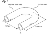
- Fig. 1 is a perspective view illustrating the constitution of a return bend tube according to the present invention
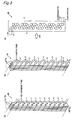
- Fig. 2 is a partially cut-away front view illustrating an example of a fin-and-tube heat exchanger that incorporates the return bend tube according to the present invention
- Fig. 3(a) is a perspective view of the heat exchanger of Fig. 2 viewed from the return bend tube
- Fig. 3(b) is a perspective view of the heat exchanger viewed from a hairpin tube
- Fig. 3(c) is a schematic view illustrating schematically the flow of refrigerant inside the heat exchanger
- Fig. 1 is a perspective view illustrating the constitution of a return bend tube according to the present invention
- Fig. 2 is a partially cut-away front view illustrating an example of a fin-and-tube heat exchanger that incorporates the return bend tube according to the present invention
- Fig. 3(a) is a perspective view of the heat exchanger of Fig. 2 viewed from the return bend tube
- FIG. 4 is an enlarged end cross-sectional view illustrating an example of a joint between a hairpin tube and a return bend tube, cut along the axial direction of the tube;
- Fig. 5(a) is an end cross-sectional view, perpendicular to the tube axis, of the return bend tube, and
- Fig. 5 (b) is a partial enlarged end cross-sectional view of Fig. 5(a) ;
- Fig. 6(a) is an end cross-sectional view, perpendicular to the tube axis, of the hairpin bend, and
- Fig. 6 (b) is a partial enlarged end cross-sectional view of Fig. 6 (a) ;
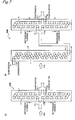
- FIG. 7 (a) and 7 (b) are schematic views illustrating schematically the flow of refrigerant inside a heat exchanger in another embodiment according to the present invention
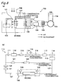
- Fig. 8(a) is a schematic view of a suction-type wind tunnel used for measuring the evaporative performance of a heat exchanger
- Fig. 8(b) is a schematic view of a refrigerant supply apparatus for supplying refrigerant to the suction-type wind tunnel of Fig. 8(a) .
- the return bend tube of the present invention is explained first. As illustrated in Figs. 1 through 3 , the return bend tube 1 of the present invention, which is used in a fin-and-tube heat exchanger 20 (hereinafter "heat exchanger" for short), is joined to the tube end of a hairpin tube 11 through which refrigerant is supplied.
- the return bend tube 1 comprises a U-shaped tube body 1a, a tube end 1b for connecting the tube end of the tube body 1a with the hairpin tube 11, and a plurality of first grooves 2 formed on the inner surface of the tube body 1a (the first grooves have been omitted in Fig. 1 , refer to Fig. 4 ).
- the return bend tube 1 is interposed between two hairpin tubes 11, to connect the respective hairpin tubes 11. As illustrated in Fig. 2 , a long-stretch refrigerant flow channel can thus be achieved by connecting in series the plurality of hairpin tubes 11, 11 ....
- the evaporative performance of the heat exchanger 20 ( Figs. 2 and 3 ) into which the return bend tube 1 is built can be enhanced by controlling as described below the inner surface groove shape of the first grooves 2 plurally formed on the tube inner surface of the return bend tube 1, as illustrated in Figs. 5 and 6 . Since the outer diameter (second outer diameter OD2) of the hairpin tube 11 joined to the return bend tube 1 ranges from 3 to 10 mm, the outer diameter (first outer diameter OD1) of the return bend tube 1 ranges preferably from 3 to 10 mm.
- the first grooves 2 of the return bend tube 1 must satisfy a groove pitch ratio (P1/P2) of 0.65 to 2.2, wherein (P1) is a first groove pitch of the return bend tube 1 in a cross section perpendicular to the tube axis, and (P2) is a second groove pitch of spiral-shaped second grooves 12 formed on the inner surface of the hairpin tube 11, in a cross section perpendicular to the tube axis.
- P1/P2 a groove pitch ratio
- a first groove cross-sectional area (S1) per groove of the first grooves 2 in a cross section perpendicular to the tube axis, and a second groove cross-sectional area (S2) per groove of the second grooves 12 in a cross section perpendicular to the tube axis must satisfy a groove cross-sectional area ratio (S1/S2) of 0.3 to 3.6. More preferably, the groove cross-sectional area ratio (S1/S2) ranges from 0.54 to 2.7.
- the groove pitch ratio (P1/P2) is less than 0.65, the number of grooves in the return bend tube 1 increases with respect to one groove in the hairpin tube 11, so that when liquid refrigerant flows from the hairpin tube 11 into the return bend tube 1, contracted flow occurs in the refrigerant film inside the tube (first grooves 2) at the return bend tube inlet side, thereby disrupting the refrigerant film.
- the refrigerant film does so in a disrupted state, whereby portions of the refrigerant film thicken at the straight-tube portion of the hairpin tube, destabilizing thus heat exchange with the exterior of the tube and eventually impairing evaporative performance.
- the groove cross-sectional area ratio (S1/S2) is less than 0.3, the cross-sectional area of the first grooves 2 is largely reduced, so that when liquid refrigerant flows from the hairpin tube 11 into the return bend tube 1, contracted flow occurs in the refrigerant film at the returnbend tube inlet, thereby disrupting the refrigerant film.
- the refrigerant film does so in a disrupted state, whereby portions of the refrigerant film thicken at the straight-tube portion of the hairpin tube 11, destabilizing thus heat exchange with the exterior of the tube and eventually impairing evaporative performance.
- an angle difference ( ⁇ 1- ⁇ 2) satisfies -15 to +15°, wherein ( ⁇ 1) is a first groove lead angle formed between the first grooves 2 and the tube axis, and ( ⁇ 2) is a second groove lead angle formed between the second grooves 12 provided on the inner surface of the hairpin tube 11 and the tube axis, while a groove depth ratio (h1/h2) satisfies 0.47 to 1.5, wherein (h1) is a first groove depth of the first grooves 2 in a cross section perpendicular to the tube axis, and (h2) is a second groove depth of the second grooves 12 in a cross section perpendicular to the tube axis.
- the first grooves 2 may have a first groove lead angle ( ⁇ 1) of 0°, i.e., the first grooves 2 may be parallel to the tube axis.
- ⁇ 1- ⁇ 2 the angle difference
- h1/h2 the groove depth ratio
- the angle difference ( ⁇ 1- ⁇ 2) is less than -15°, i.e. when the first groove lead angle ( ⁇ 1) is smaller than (second groove lead angle ( ⁇ 2)-15'), the refrigerant film splashes at the apex of first fins 3 formed between the first grooves 2, whereby the refrigerant film becomes disrupted (separated flow) in the return bend tube inlet side.
- the refrigerant film does so in a disrupted state, whereby portions of the refrigerant film thicken at the straight-tube portion of the hairpin tube 11, destabilizing thus heat exchange with the exterior of the tube and eventually impairing evaporative performance.
- angle difference ( ⁇ 1- ⁇ 2) exceeds +15°, i.e. if the first groove lead angle ( ⁇ 1) is greater than (second groove lead angle ( ⁇ 2) +15°), pressure loss on the return bend tube side becomes greater when the liquid refrigerant flows from the hairpin tube 11 into the return bend tube 1, thereby giving rise to contracted flow in the refrigerant film at the return bend tube inlet side and disrupting the refrigerant film.
- the refrigerant film does so in a disrupted state, whereby portions of the refrigerant film thicken at the straight-tube portion of the hairpin tube 11, destabilizing thus heat exchange with the exterior of the tube and eventually impairing evaporative performance.
- the direction of the first groove lead angle ( ⁇ 1) formed between the first grooves 2 and the tube axis, and the direction of the second groove lead angle ( ⁇ 2) formed between the second grooves 12 provided on the inner surface of the hairpin tube 11 and the tube axis, are preferably the same direction. If the direction of the first groove lead angle ( ⁇ 1) and the direction of the second groove lead angle ( ⁇ 2) are different, refrigerant pressure loss at the return bend tube 1 becomes greater, which impairs evaporative performance.
- the groove depth ratio (h1/h2) is smaller than 0.47, the refrigerant film of the first grooves 2 tends to separate from the inner surface at the return bend tube inlet side, so that the refrigerant film splashes and becomes disrupted (separated flow).
- the refrigerant film does so in a disrupted state, wherebyportions of the refrigerant film thicken at the straight-tube portion of the hairpin tube 11, destabilizing thus heat exchange with the exterior of the tube and eventually impairing evaporative performance.
- the first fins 3 of the return bend tube 1 offer resistance when the liquid refrigerant flows from the hairpin tube 11 into the return bend tube 1, thereby giving rise to contracted flow in the refrigerant film at the return bend tube inlet side and disrupting the refrigerant film.
- the refrigerant film does so in a disrupted state, wherebyportions of the refrigerant film thicken at the straight-tube portion of the hairpin tube 11, destabilizing thus heat exchange with the exterior of the tube and eventually impairing evaporative performance.
- a first fin apex angle ( ⁇ 1) and a first fin root radius (r1) of the first fins 3 formed between first grooves 2 of the return bend tube 1 are identical to a second fin apex angle ( ⁇ 2) and a second fin root radius (r2) of the second fins 13 formed between second grooves 12 of the hairpin tube 11.
- the first fin apex angle ( ⁇ 1) ranges from 4.5 to 45°
- the first fin root radius (r1) ranges from 1/12 to 1/2 of the first groove depth (h1).
- the first fin apex angle ( ⁇ 1) ranges from 4.5 to 28.5°
- the first fin root radius (r1) ranges from 1/12 to 1/4 of the first groove depth (h1).
- the refrigerant film When flowing thus into the next hairpin tube 11, the refrigerant film does so in a disrupted state, whereby portions of the refrigerant film thicken at the straight-tube portion of the hairpin tube 11, destabilizing thus heat exchange with the exterior of the tube and eventually impairing evaporative performance.
- the reduced cross-sectional area of the first grooves 2 is likely to give rise to contracted flow of the refrigerant film at the return bend tube inlet side during inflow of refrigerant from the hairpin tube 11 into the return bend tube 1, thereby disrupting the refrigerant film.
- the refrigerant film does so in a disrupted state, whereby portions of the refrigerant film thicken at the straight-tube portion of the hairpin tube 11, destabilizing thus heat exchange with the exterior of the tube and eventually impairing evaporative performance.
- first fin root radius (r1) is smaller than 1/12 of the first groove depth (h1), flowing resistance of the refrigerant drops thanks to the increased cross-sectional area of the first grooves 2, whereas the holding ability of the refrigerant film becomes greatly reduced owing to the widening of the groove bottom of the first grooves 2 when liquid refrigerant flows from the hairpin tube 11 into the return bend tube 1. As a result, the formation of "annular flow” breaks down, and the refrigerant film is disrupted.
- the refrigerant film When flowing thus into the next hairpin tube 11, the refrigerant film does so in a disrupted state, whereby portions of the refrigerant film thicken at the straight-tube portion of the hairpin tube 11, destabilizing thus heat exchange with the exterior of the tube and eventually impairing evaporative performance.
- the reduced cross-sectional area of the first grooves 2 is likely to give rise to contracted flow of the refrigerant film at the return bend tube inlet side during inflow of refrigerant from the hairpin tube 11 into the return bend tube 1, thereby disrupting the refrigerant film.
- the refrigerant film does so in a disrupted state, whereby portions of the refrigerant film thicken at the straight-tube portion of the hairpin tube 11, destabilizing thus heat exchange with the exterior of the tube and eventually impairing evaporative performance.
- the evaporative performance of the heat exchanger into which the return bend tube 1 is built can be enhanced by restricting the tube body 1a of the return bend tube 1 as described below.
- the length (L) of the return bend tube 1 (tube body 1a) measures preferably 1.0 to 1.5 times the pitch (P) thereof.
- the length (L) is the distance between the tube end 1b and the outer face of the bending apex of the U-shaped tube body 1a.
- the pitch (P) is the distance between the centers of both tube ends of the U-shaped tube body 1a.
- the resulting shorter length from the entrance of the return bend tube to the point where bending starts precludes sufficient formation of "annular flow” and gives rise to splashing of the refrigerant film on the inner side of the bending portion, which disrupts the refrigerant film (separated flow).
- the refrigerant film does so in a disrupted state, whereby portions of the refrigerant film thicken at the straight-tube portion of the hairpin tube, destabilizing thus heat exchange with the exterior of the tube and eventually impairing evaporative performance.
- the resulting longer length from the inlet side of the return bend tube to the point where bending starts facilitates formation of "annular flow", whereas it increases pressure loss of the flowing refrigerant in return bend tube 1, whereby evaporative performance may be impaired.
- the return bend tube 1 (tube body 1a) comprises preferably a material having a lower thermal conductivity than the material of the hairpin tube.
- a heat exchanger 20 Figs. 2 and 3
- the return bend tube 1 is used outside the heat exchange portion.
- the material of the return bend tube 1 has a higher thermal conductivity than the material of the hairpin tube, therefore, there occurs heat loss at the portion of the return bend tube 1.
- Phosphorus deoxidized copper has been often used conventionally as the material of the hairpin tube and of the return bend tube 1 (tube body 1a), with brazing as the method employed for connecting the tubes.
- the tube ends of both tubes are heated to about 800 to 900°C by means of a gas burner or the like.
- phosphorus deoxidized copper is used in the return bend tube 1 (tube body 1a)
- such brazing heat lowers the strength of the return bend tube 1 (heat-affected portion), and breaking of the tube tends to occur due to the internal pressure of the tube in use of the heat exchanger.
- a first tube wall thickness (T1) ( Fig. 4 ) of the return bend tube 1 (tube body 1a) must be made thicker.
- the return bend tube 1 (tube body 1a) can be made more lightweight as a result.
- Preferred heat-resistant copper alloys include, for instance, Cu-Sn-P alloys, Cu-Sn-Zn-P alloys and the like, having a compression strength of 10 MPa or more at room temperature even after heating at 850°C.
- a heat-resistant copper alloy identical to that of the return bend tube 1 may be used also in the hairpin tube.
- the first maximum inner diameter (ID1) of the return bend tube 1 (tube body 1a) and the second maximum inner diameter (ID2) of the hairpin tube 11 satisfy the relationship (ID1) ⁇ (ID2). If (ID1) ⁇ (ID2), "annular flow" of the refrigerant film formed inside the return bend tube 1 becomes spreaded flow of the refrigerant film of the inlet portion of the hair pin tube 11, and the thickness of the refrigerant film becomes uneven, which disrupts the refrigerant film.
- the refrigerant film flows in a disrupted state in the vicinity of the inlet of the next hairpin tube, whereby part of the refrigerant film thickens, destabilizing thus heat exchange with the exterior of the tube and eventually impairing evaporative performance.
- the hairpin tube 11 that, as illustrated in Figs. 2 and 3 , make up the heat exchanger 20 together with the return bend tubes 1 according to the present invention.
- the hairpin tube 11 has the plurality of spiral second grooves 12 inside the tube, wherein the inner groove shape of the second grooves 12 is preferably restricted as described below.
- 3 to 10 mm tubes are ordinarily used, and hence tubes having an outer diameter (second outer diameter OD2) ranging from 3 to 10 mm are preferably used as the hairpin tubes 11.
- phosphorus deoxidized copper is preferably used as the material of the hairpin tubes 11.
- a heat-resistant copper alloy which has better heat resistance than phosphorus deoxidized copper, may also be used herein.
- the second groove pitch (P2) ranges from 0.37 to 0.42 mm and the second groove cross-sectional area (S2) from 0.04 to 0.06 mm 2 .
- the fluidity of the tube material into the groove portions of the groove forming tool decreases during formation of the second grooves 12 on the tube inner surface, which entails a greater press force from the exterior of the tube.
- the grooving tool becomes prone to break, while the second grooves 12 become harder to be shaped stably on the tube inner surface.
- the liquid refrigerant film is hard to form the thin layer in the second grooves 12 inside the tube.
- the refrigerant film inside the tube turns resistance to heat exchange with exterior of the tube, and evaporative performance is eventually impaired.
- the second groove lead angle ( ⁇ 2) is 15° or more.
- the second groove lead angle ( ⁇ 2) is smaller than 15°, formation of "swirling flow" by the refrigerant film inside the tube is insufficient, which is likely to impair evaporative performance.
- lack of the second groove lead angle reduces formation of homogeneous "annular flow" of the refrigerant film on the second grooves 12, so that the refrigerant film becomes uneven at the straight-tube portion of the hairpin tube 11, destabilizing thus heat exchange with the exterior of the tube and eventually impairing evaporative performance.
- the second groove lead angle ( ⁇ 2) exceeds 45°, the rolling speed of formation of the second grooves 12 on the tube inner side tends to decrease sharply, which makes it more difficult to manufacture stably a long hairpin tube 11. Accordingly, the second groove lead angle ( ⁇ 2) is preferably of 45° or less.
- the second groove depth (h2) ranges preferably from 0.10 to 0.28 mm.
- the second groove depth (h2) is smaller than 0.10 mm, the second fins 13 formed between the second grooves 12 on the tube inner side drop below the level of the refrigerant inside the tube, and hence the fins become buried by the refrigerant film.
- the effective heat transfer area inside the tube decreases dramatically as a result, and evaporative performance is impaired.
- the groove forming tool for instance, a grooved plug
- the second groove forming tool becomes prone to break during formation of the second grooves 12 on the tube inner surface, and the second grooves 12 become harder to be shaped stably on the tube inner surface.
- the second fin apex angle ( ⁇ 2) ranges preferably from 5 to 45°.
- the second fin apex angle ( ⁇ 2) is smaller than 5°, the second fins 13 are likelier to collapse or break during mechanical tube expansion (not shown in the figure) to incorporate the hairpin tubes 11 into a heat exchanger 20 for air-conditioners.
- the groove forming tool becomes prone to get chipped during shaping on the second grooves 12 and the second fins 13 on the tube inner surface, so that the second grooves 12 become harder to shape stably on the tube inner surface.
- the second fin apex angle ( ⁇ 2) exceeds 45°, the cross-sectional area of the second grooves 12 shrinks dramatically, thereby impairing heat-transfer performance.
- the cross-sectional area of the second fins 13 increases, thereby increasing the weight of the hairpin tube 11 and making it harder to build a light-weight heat exchanger 20.
- the second fin root radius (r2) ranges from 1/10 to 1/3 of the second groove depth (h2).
- the second fin root radius (r2) is smaller than 1/10 of the second groove depth (h2) and the second fins 13 are high, formability of the second fins 13 (second grooves 12) worsens, making it more difficult to achieve second fins 13 of a predetermined shape, and increasing the likelihood of damage in the groove forming tool that abuts the root of the second grooves 12 on the tube inner surface.
- the second fin root radius (r2) is larger than 1/3 of the second groove depth (h2), the cross-sectional area of the second fins 13 increases, the second wall thickness (T2) of the hairpin tube 11 increases, and the hairpin tube 11 becomes heavier.
- the second maximum inner diameter (ID2) of the hairpin tube 11 is preferably 0.80 to 0.96 of the outer diameter (OD2) of the hairpin tube 11.
- the second wall thickness (T2) becomes thicker, thereby increasing the weight of the hairpin tube 11 and making it harder to build a light-weight heat exchanger 20 ( Figs. 2 and 3 ).
- the second maximum inner diameter (ID2) exceeds 0.96 of the outer diameter (OD2) of the hairpin tube 11, the second wall thickness (T2) becomes thinner, thereby reducing the tube strength of the hairpin tube 11 and increasing the likelihood of tube breakage in use of the heat exchanger 20.
- a method for manufacturing the return bend tube and the hairpin tube is explained next.
- the return bend tube and the hairpin tube are manufactured, for instance, in accordance with the following conventional manufacturing method.
- a soft material is ordinarily used as the tube stock employed in the below-described first step.
- the below-described first through third steps are carried out sequentially using tube rolling machine provided with a diameter-reducing apparatus at a preliminary state and a final stage.
- the inner surface grooved tube is wound as a level wound coil, is annealed into a soft material in an annealing furnace, and is used in a fourth step to manufacture a return bend tube and a hairpin tube.
- Tube stockmade of a base material such as phosphorus deoxidized copper or a heat-resistant copper alloy is drawn by passing between a diameter-reducing die and a diameter-reducing plug, to subject thereby the tube stock to a first diameter-reducing process.
- a grooved plug is inserted into the tube stock that was reduced in the first step, and then outer surface of the tube stock is rolled at the portion inside which the grooved plug is located by a plurality of rolling balls or rolling rolls, to subject thereby the tube stock to a second diameter-reducing process. Simultaneously therewith, the groove shape of the grooved plug is transferred to the inner surface of the reduced tube stock, to form thereby the first grooves 2 or the second grooves 12 ( Fig. 4 ).
- the grooved plug has herein a groove shape that corresponds to the above-described inner surface groove shapes ( Figs. 5 and 6 ).
- OD1 first outer diameter
- OD2 second outer diameter
- the inner-surface grooved tube manufactured in the third step is then bent using a predetermined jig, to manufacture thereby a return bend tube 1 and a hairpin tube 11 having a predetermined shape ( Figs. 1 and 2 ).
- the heat exchanger 20 wherein refrigerant is supplied through tubing, comprises a hairpin tube portion 23, in which a plurality hairpin tubes 11, 11... are arranged at a predetermined bending pitch Pa; a return bend tube portion 22 having a plurality of return bend tubes 1, 1... joined by tube ends 1b, 1b ( Fig. 1 ) to the tube end portions of respective hairpin tubes 11, 11... of the hairpin tube portion 23; and a fin portion 21 comprising a plurality of fins 21a, 21a ...
- the hairpin tubes 11 may also be arranged in a plurality of columns with a predetermined column-direction pitch Pc. As illustrated in Fig.
- the refrigerant supplied inside the tubes ob the heat exchanger 20 flows in the same direction as that of the flow of the air with which the heat exchanger 20 is blown, during refrigerant condensation, and in the reverse direction, during refrigerant evaporation.
- At least part of the return bend tube portion 22 comprises the return bend tube 1 on the inner surface of which there are formed the above-described plurality of first grooves 2 ( Fig. 5 ).
- the inner-surface groove shape of the return bend tube for instance, the groove pitch ratio (P1/P2), the groove cross-sectional area ratio (S1/S2), the groove depth ratio (h1/h2) ( Figs. 5 and 6 ), the angle difference between groove lead angles ( ⁇ 1- ⁇ 2) ( Fig. 4 ), or the first maximum inner diameter (ID1), may vary depending on the location of the return bend tube portion 22, in consideration of the flow of refrigerant (upstream, downstream) in the heat exchanger 20.
- inner-surface smooth return bend tubes may also be used in at least part of the return bend tube portion 22.
- the heat exchanger of the present invention may be a two-pass heat exchanger 20A where the refrigerant flow channel as a whole is branched, and a partial two-pass heat exchanger 20B in which part of the refrigerant flow channel is branched.
- the refrigerant flow channel is branched into two flow channels (refrigerant flow channel A and refrigerant flow channel B), branching is not limited thereto, and the refrigerant may be branched into three or more flow channels.
- a branched refrigerant flow channel (refrigerant flow channel A and refrigerant flow channel B) may in turn be branched into the plurality of refrigerant flow channels.
- the partial two-pass heat exchanger 20B of Fig. 7(b) there is one branching location, but there may be two or more such locations. That is, the one-pass heat exchanger 20 having no branched refrigerant flow channel, as illustrated in Fig. 3(c) , may be joined to the plurality of two-pass heat exchangers 20A.
- forming the plurality of refrigerant flow channels has the effect of reducing the number of hairpin tubes and return bend tubes constituting one refrigerant flow channel (refrigerant flow channel A or refrigerant flow channel B) compared with number in the above-described one-pass heat exchanger 20 (from 11 stages to 6 stages in Fig. 3(c) and Fig. 7 ). As a result, this reduces refrigerant pressure loss and further enhances evaporative performance.
- the refrigerant used in the heat exchanger 20 of the present invention is a hydrofluorocarbon (HFC) refrigerant, preferably, for instance, of R410 type, and more preferably R410A, which is a 50/50% mixture of difluoroethane (R32) and pentafluoroethane (R125) .
- HFC hydrofluorocarbon
- R410A a 50/50% mixture of difluoroethane
- R125 pentafluoroethane
- R410 refrigerants have excellent evaporative performance, they also have a high working pressure, which tends to result in large compressors.
- an R407 type having a slightly lower evaporative performance but also a lower working pressure than R410 type, may be used as the refrigerant of the present invention.
- phosphorus deoxidized cooper having an alloy number C1220 or oxygen-free copper having an alloy number C1020, as per JISH3300 was melted, cast, hot-extruded, cold-rolled and cold-drawn to yield a tube stock in Examples 1 to 6 and 8 to 20, while a Cu-Sn-P (0.65wt%, 0.03wt%, balance Cu) heat-resistant alloy was similarly processed to yield a tube stock in Example 7.
- the tube stock was subjected to a first diameter-reducing process, then the reduced tube stock was subj ected to a second diameter-reducing process while forming thereon spiral grooves (or parallel grooves) as inner-surface groove shapes given in Table 1 and Table 2.
- the grooved tube stock was then subjected to a third diameter-reducing process and was annealed to manufacture thereby a test tube (for return bend tubes) having a first outer diameter (OD1) of 7 mm.
- Test tubes (for hairpin tubing) having a second outer diameter (OD2) of 7 mm were manufactured in accordance with the same manufacturing method, using herein a phosphorus deoxidized cooper having an alloy number C1220 as per JISH3300.
- a fin-and-tube heat exchanger (one-pass heat exchanger) 20 as illustrated in Fig. 2 and Figs. 3(a) and 3(b) was manufactured then using the respective test tubes.
- the test tubes (for hairpin tubes) were first bent, by the middle portion thereof, into a hairpin shape with a predetermined bending pitch (Pa), to manufacture a plurality of hairpin tubes 11.
- the plurality of hairpin tubes 11 were then passed through the plurality of fins 21a arranged parallel to one another at a predetermined spacing (fin pitch (Pb)).
- a bullet for yielding an expansion rate of 105.5% with respect to the outer diameter of the a copper tube (hairpin tube 11) was the inserted into the hairpin tubes 11, then the tubes were expanded using a shrinkage-type tube expander, and the hairpin tubes 11 were joined to the fins 21a.
- the test tubes (for return bend tubes) were then bent to a predetermined length L and pitch (P) ( Fig. 1 ), to manufacture the plurality of return bend tubes 1.
- the tube ends of the adjacent hairpin tube 11 were further expanded, the return bend tubes 1 provided with a ring of phosphorus copper brazing alloy (BCuP-2) were fitted to the ends of the hairpin tube 11, and then both tubes were heat-brazed together (850°C, 1 minute) using a burner, while nitrogen gas was streamed through the interior of the tubes to prevent oxidation.
- BCuP-2 phosphorus copper brazing alloy
- Example 9 The same test tubes (hairpin tube, return bend tube) as in Example 1 were used in Example 9, and a fin-and-tube heat exchanger (two-pass heat exchanger) 20A such as the one illustrated in Fig. 7 (a) was manufactured in the same way as in Example 1.
- the hairpin tubes 11 of refrigerant flow channels A and B comprised 2 columns and 6 stages.
- Comparative example 1 was identical to Example 1 except that a smooth tube, without grooves formed on the inner surface, was used herein as the test tube (return bend tube).
- Comparative examples 2 to 5 were identical to Example 1 except that herein there were used inner surface grooved tubes in which the groove pitch ratio (P1/P2) and/or the groove cross-sectional area ratio (S1/S2) lay outside the ranges in the claims of the present invention.
- a heat exchanger (one-pass heat exchanger) 20 was manufactured in the same way as in Example 1.
- Fig. 8(a) is a schematic view illustrating a measurement apparatus for manufacturing evaporative performance.
- the measurement apparatus comprises a suction-type wind tunnel 100 having a thermo-hygrostatic function, a refrigerant supply apparatus 110 ( Fig. 8(b) ), andanair-conditioner (not shown).
- a heat exchanger 20 (20A) is arranged in the flow path of air that flows in through an air flow inlet 108 and is discharged through an air discharge outlet 109, with air samplers 101, 102 arranged respectively upstream and downstream of the heat exchanger 20 (20A).
- the air samplers 101, 102 are coupled to respective thermohygrometer boxes 103, 104.
- thermohygrometer boxes 103, 104 measure the dry-bulb temperature and the wet-bulb temperature of air sampled by the air samplers 101, 102, to measure the temperature and the humidity of the air.
- An induced draft fan 105 for discharging air to the air discharge outlet 109 is arranged downstream of the air sampler 102.
- Flow regulators 106, 106 for adjusting the airflow passing through the heat exchanger 20(20A) are provided between the heat exchanger 20(20A) and the air sampler 102, and between the air sampler 102 and the induced draft fan 105.
- Fig. 8(a) illustrates a schematic view of the refrigerant supply apparatus 110.
- the reference numeral 107 denotes refrigerant piping, 111 a sight glass, 112 a heat exchanger for heating and cooling a liquid (refrigerant), 113 a dryer, 114 a liquid (refrigerant) receiver, 115 a fusible plug, 116 a condenser, 117 an oil separator, 118 a compressor, 119 an accumulator, 120 an evaporator, 121 an expansion valve and 122 a flow meter.
- Pressure and temperature-adjusted refrigerant is supplied via the refrigerant piping 107 to the hairpin tubes 11 ( Fig.
- Pressure gauges 123 for measuring the temperature and the pressure of the refrigerant are provided also at the inlet and the outlet of the heat exchanger 20(20A).
- the air-conditioner (not shown) supplies air of controlled temperature and humidity to the air flow inlet 108 of the suction-type wind tunnel 100.
- Example 21 was identical to Example 1 except that herein an inner surface grooved tube having a first wall thickness (T1) of 0.20 mm and comprising a Cu-Sn-P material (heat-resistant alloy of 0.65wt% Sn, 0.03wt% P, balance Cu), was used as the test tube (return bend tube).
- Example 22 was identical to Example 1 except that herein an inner surface grooved tube having a first wall thickness (T1) of 0. 34 mm was used as the test tube (return bend tube) .
- a heat exchanger one-pass heat exchanger was manufactured in the same way as in Example 1 .
- the heat exchangers of Example 1, Example 21 and Example 22 were subjected to a pressure resistance test by water pressure. The pressure at which the return bend tube portion (return bend tube) of the heat exchanger ruptures, i.e. the compression strength, was measured using a Bourdon tube pressure gauge. The results are given in Table 4.
- Example 1 Material: C1220 Material: C1220 Outer diameter (CD1) : 7.00mm Outer diameter (OD2): 7.00mm 13.0 MPa First wall thickness (T1) : 0.24mm Second wall thickness (T2) : 0.24mm Other groove shapes: Same as Table 1 Other groove shapes: Same as Table 1 Example 21 Material: Cu-Sn-P Material: C1220 Outer diameter (OD1) : 7.00mm Outer diameter (OD2) : 7.00mm 13.5 MPa First wall thickness(T1) : 0.20mm Second wall thickness (T2) : 0.24mm Other groove shapes: Same as Example 1 Other groove shapes: Same as Example 1 Example 22 Material: C1220 Material: C1220 Outer diameter (OD1) : 7.00mm Outer diameter (OD2) : 7.00mm 13.5 MPa First wall thickness (T1) : 0.34mm Second wall thickness (T2) : 0.24mm Other groove shapes: Same as Example 1 Other groove shapes: Same as Example 1 Other groove shapes: Same as Example 1 Other groove shapes: Same as Example 1 Other groove shapes: Same as Example 1
- Example 21 has higher compression strength than that of Example 1, thanks to a smaller loss of strength through brazing, even though the first wall thickness (T1) of the return bend tube was thinner than that of Example 1.
Landscapes
- Engineering & Computer Science (AREA)
- Physics & Mathematics (AREA)
- Thermal Sciences (AREA)
- Mechanical Engineering (AREA)
- General Engineering & Computer Science (AREA)
- Geometry (AREA)
- Heat-Exchange Devices With Radiators And Conduit Assemblies (AREA)
Applications Claiming Priority (2)
| Application Number | Priority Date | Filing Date | Title |
|---|---|---|---|
| JP2006193721A JP4728897B2 (ja) | 2006-07-14 | 2006-07-14 | リターンベンド管およびフィンアンドチューブ型熱交換器 |
| PCT/JP2007/063807 WO2008007694A1 (en) | 2006-07-14 | 2007-07-11 | Fin-and-tube type heat exchanger, and its return bend pipe |
Publications (3)
| Publication Number | Publication Date |
|---|---|
| EP2042825A1 true EP2042825A1 (de) | 2009-04-01 |
| EP2042825A4 EP2042825A4 (de) | 2010-06-16 |
| EP2042825B1 EP2042825B1 (de) | 2018-10-03 |
Family
ID=38923250
Family Applications (1)
| Application Number | Title | Priority Date | Filing Date |
|---|---|---|---|
| EP07790611.3A Not-in-force EP2042825B1 (de) | 2006-07-14 | 2007-07-11 | Gerippter rohrwärmetauscher und rücklaufbogenrohr |
Country Status (6)
| Country | Link |
|---|---|
| EP (1) | EP2042825B1 (de) |
| JP (1) | JP4728897B2 (de) |
| KR (1) | KR20080108620A (de) |
| CN (1) | CN101466992B (de) |
| MY (1) | MY144548A (de) |
| WO (1) | WO2008007694A1 (de) |
Cited By (6)
| Publication number | Priority date | Publication date | Assignee | Title |
|---|---|---|---|---|
| WO2013139507A1 (de) * | 2012-03-19 | 2013-09-26 | Bundy Refrigeration International Holding B.V. | Wärmetauscher, verfahren zu seiner herstellung sowie verschiedene anlagen mit einem derartigen wärmetauscher |
| WO2014130281A1 (en) * | 2013-02-21 | 2014-08-28 | Carrier Corporation | Tube structures for heat exchanger |
| WO2016032759A1 (en) * | 2014-08-25 | 2016-03-03 | J R Thermal LLC | Temperature glide thermosyphon and heat pipe |
| EP3483545A1 (de) * | 2017-11-08 | 2019-05-15 | Carrier Corporation | Wärmetauscherrohr für das endprodukt eines klimatisierungssystems und herstellungsverfahren dafür |
| US10520255B2 (en) | 2016-11-11 | 2019-12-31 | Johnson Controls Technology Company | Finned heat exchanger U-bends, manifolds, and distributor tubes |
| US11007592B2 (en) | 2015-07-30 | 2021-05-18 | Denso Aircool Corporation | Heat exchanger and method for producing same |
Families Citing this family (11)
| Publication number | Priority date | Publication date | Assignee | Title |
|---|---|---|---|---|
| DE102008024562B4 (de) * | 2008-05-21 | 2021-06-10 | Stiebel Eltron Gmbh & Co. Kg | Wärmepumpenvorrichtung mit einem Lamellenrohrwärmeübertrager als Verdampfer |
| CN101829827B (zh) * | 2010-06-12 | 2012-02-01 | 西安交通大学 | 内翅片管高温真空钎焊夹具 |
| CN102235779B (zh) * | 2011-07-19 | 2013-07-24 | 海信科龙电器股份有限公司 | 空调换热器 |
| KR20140106552A (ko) * | 2011-12-07 | 2014-09-03 | 파나소닉 주식회사 | 핀 튜브형 열교환기 |
| JP2013134024A (ja) * | 2011-12-27 | 2013-07-08 | Panasonic Corp | 冷凍サイクル装置 |
| CN103307919A (zh) * | 2013-06-24 | 2013-09-18 | 苏州市金翔钛设备有限公司 | 一种钛盘管 |
| CN104279910A (zh) * | 2013-07-11 | 2015-01-14 | 上海林内有限公司 | 用于热交换器的管接头 |
| ITMI20131684A1 (it) * | 2013-10-11 | 2015-04-12 | Frimont Spa | Condensatore per macchina di fabbricazione del ghiaccio, metodo per la sua realizzazione, e macchina di fabbricazione del ghiaccio che incorpora tale condensatore |
| WO2016009565A1 (ja) * | 2014-07-18 | 2016-01-21 | 三菱電機株式会社 | 冷凍サイクル装置 |
| KR102097462B1 (ko) | 2019-05-09 | 2020-04-06 | (주)에프원공조 | 열교환기용 리턴벤드 및 그 제조방법 |
| KR102186154B1 (ko) * | 2019-07-09 | 2020-12-03 | 엘지전자 주식회사 | 열교환기 및 열교환기의 제조방법 |
Family Cites Families (8)
| Publication number | Priority date | Publication date | Assignee | Title |
|---|---|---|---|---|
| JPS63154986A (ja) | 1986-12-18 | 1988-06-28 | Seiko Instr & Electronics Ltd | 時計用外装部品の固定方法 |
| JPH04122986A (ja) | 1990-09-13 | 1992-04-23 | Fujitsu Ltd | 画像データdma転送制御方式 |
| JPH0926280A (ja) * | 1995-07-12 | 1997-01-28 | Sanyo Electric Co Ltd | 内面溝付冷媒配管 |
| JPH10292992A (ja) * | 1997-04-18 | 1998-11-04 | Toshiba Corp | 熱交換器の製造方法 |
| JPH11190597A (ja) * | 1997-12-26 | 1999-07-13 | Hitachi Cable Ltd | 熱交換器の伝熱管接続方法 |
| JP4300013B2 (ja) * | 2001-10-22 | 2009-07-22 | 昭和電工株式会社 | 熱交換器用フィン付き管、熱交換器、熱交換器用フィン付き管の製造方法および熱交換器の製造方法 |
| JP4119836B2 (ja) * | 2003-12-26 | 2008-07-16 | 株式会社コベルコ マテリアル銅管 | 内面溝付伝熱管 |
| JP4422590B2 (ja) * | 2004-09-02 | 2010-02-24 | 株式会社コベルコ マテリアル銅管 | リターンベンド管およびフィンアンドチューブ型熱交換器 |
-
2006
- 2006-07-14 JP JP2006193721A patent/JP4728897B2/ja not_active Expired - Fee Related
-
2007
- 2007-07-11 KR KR1020087027945A patent/KR20080108620A/ko not_active Ceased
- 2007-07-11 MY MYPI20084450A patent/MY144548A/en unknown
- 2007-07-11 WO PCT/JP2007/063807 patent/WO2008007694A1/ja not_active Ceased
- 2007-07-11 CN CN2007800213773A patent/CN101466992B/zh active Active
- 2007-07-11 EP EP07790611.3A patent/EP2042825B1/de not_active Not-in-force
Cited By (8)
| Publication number | Priority date | Publication date | Assignee | Title |
|---|---|---|---|---|
| WO2013139507A1 (de) * | 2012-03-19 | 2013-09-26 | Bundy Refrigeration International Holding B.V. | Wärmetauscher, verfahren zu seiner herstellung sowie verschiedene anlagen mit einem derartigen wärmetauscher |
| WO2014130281A1 (en) * | 2013-02-21 | 2014-08-28 | Carrier Corporation | Tube structures for heat exchanger |
| WO2016032759A1 (en) * | 2014-08-25 | 2016-03-03 | J R Thermal LLC | Temperature glide thermosyphon and heat pipe |
| US9777967B2 (en) | 2014-08-25 | 2017-10-03 | J R Thermal LLC | Temperature glide thermosyphon and heat pipe |
| US11007592B2 (en) | 2015-07-30 | 2021-05-18 | Denso Aircool Corporation | Heat exchanger and method for producing same |
| US10520255B2 (en) | 2016-11-11 | 2019-12-31 | Johnson Controls Technology Company | Finned heat exchanger U-bends, manifolds, and distributor tubes |
| US11604032B2 (en) | 2016-11-11 | 2023-03-14 | Johnson Controls Tyco IP Holdings LLP | Finned heat exchanger U-bends, manifolds, and distributor tubes |
| EP3483545A1 (de) * | 2017-11-08 | 2019-05-15 | Carrier Corporation | Wärmetauscherrohr für das endprodukt eines klimatisierungssystems und herstellungsverfahren dafür |
Also Published As
| Publication number | Publication date |
|---|---|
| MY144548A (en) | 2011-09-30 |
| EP2042825B1 (de) | 2018-10-03 |
| CN101466992B (zh) | 2010-12-22 |
| JP4728897B2 (ja) | 2011-07-20 |
| CN101466992A (zh) | 2009-06-24 |
| EP2042825A4 (de) | 2010-06-16 |
| JP2008020150A (ja) | 2008-01-31 |
| KR20080108620A (ko) | 2008-12-15 |
| WO2008007694A1 (en) | 2008-01-17 |
Similar Documents
| Publication | Publication Date | Title |
|---|---|---|
| EP2042825B1 (de) | Gerippter rohrwärmetauscher und rücklaufbogenrohr | |
| JP4759226B2 (ja) | 拡管用工具およびそれを使用した拡管方法 | |
| JP2008215733A (ja) | フィンアンドチューブ型熱交換器 | |
| EP2213953B1 (de) | Klimaanlage | |
| EP2232187B1 (de) | Wärmetauscherrohr | |
| EP2682704B1 (de) | Wärmetauscher, kühlschrank mit dem wärmetauscher und klimaanlage mit dem wärmetauscher | |
| EP2278252A1 (de) | Wärmetauscher und klimaanlage damit | |
| US12055329B2 (en) | Pipe coupling structure and refrigeration cycle apparatus | |
| US9874402B2 (en) | Heat exchanger, refrigeration cycle apparatus, and method of manufacturing heat exchanger | |
| JP2002098486A (ja) | 熱交換器及びその製造方法 | |
| CN100523703C (zh) | 高压制冷剂用的内表面带槽的传热管 | |
| JP4119836B2 (ja) | 内面溝付伝熱管 | |
| US20160187072A1 (en) | Fin-tube heat exchanger | |
| WO2019039401A1 (ja) | 凝縮器 | |
| JP2005076915A (ja) | 複合伝熱管 | |
| JP4422590B2 (ja) | リターンベンド管およびフィンアンドチューブ型熱交換器 | |
| CN105026869B (zh) | 用于热交换器的管道结构 | |
| WO2013125625A1 (ja) | フィン・アンド・チューブ型熱交換器用伝熱管及びそれを用いたフィン・アンド・チューブ型熱交換器 | |
| CN104040281A (zh) | 空气调节机 | |
| WO2017208419A1 (ja) | フィンチューブ型熱交換器、このフィンチューブ型熱交換器を備えたヒートポンプ装置、および、フィンチューブ型熱交換器の製造方法 | |
| JP2005315556A (ja) | 内面溝付管 | |
| JP2013096651A (ja) | 内面溝付伝熱管及び内面溝付伝熱管を備えた熱交換器及びその製造方法 | |
| JP4015047B2 (ja) | 内面溝付伝熱管 | |
| JP4119765B2 (ja) | 内面溝付伝熱管 | |
| JP6802697B2 (ja) | 内面溝付管 |
Legal Events
| Date | Code | Title | Description |
|---|---|---|---|
| PUAI | Public reference made under article 153(3) epc to a published international application that has entered the european phase |
Free format text: ORIGINAL CODE: 0009012 |
|
| 17P | Request for examination filed |
Effective date: 20081204 |
|
| AK | Designated contracting states |
Kind code of ref document: A1 Designated state(s): AT BE BG CH CY CZ DE DK EE ES FI FR GB GR HU IE IS IT LI LT LU LV MC MT NL PL PT RO SE SI SK TR |
|
| AX | Request for extension of the european patent |
Extension state: AL BA HR MK RS |
|
| A4 | Supplementary search report drawn up and despatched |
Effective date: 20100519 |
|
| DAX | Request for extension of the european patent (deleted) | ||
| 17Q | First examination report despatched |
Effective date: 20121009 |
|
| GRAP | Despatch of communication of intention to grant a patent |
Free format text: ORIGINAL CODE: EPIDOSNIGR1 |
|
| STAA | Information on the status of an ep patent application or granted ep patent |
Free format text: STATUS: GRANT OF PATENT IS INTENDED |
|
| INTG | Intention to grant announced |
Effective date: 20180417 |
|
| GRAS | Grant fee paid |
Free format text: ORIGINAL CODE: EPIDOSNIGR3 |
|
| GRAA | (expected) grant |
Free format text: ORIGINAL CODE: 0009210 |
|
| STAA | Information on the status of an ep patent application or granted ep patent |
Free format text: STATUS: THE PATENT HAS BEEN GRANTED |
|
| AK | Designated contracting states |
Kind code of ref document: B1 Designated state(s): AT BE BG CH CY CZ DE DK EE ES FI FR GB GR HU IE IS IT LI LT LU LV MC MT NL PL PT RO SE SI SK TR |
|
| REG | Reference to a national code |
Ref country code: GB Ref legal event code: FG4D |
|
| REG | Reference to a national code |
Ref country code: CH Ref legal event code: EP Ref country code: AT Ref legal event code: REF Ref document number: 1049052 Country of ref document: AT Kind code of ref document: T Effective date: 20181015 |
|
| REG | Reference to a national code |
Ref country code: DE Ref legal event code: R096 Ref document number: 602007056369 Country of ref document: DE Ref country code: IE Ref legal event code: FG4D |
|
| REG | Reference to a national code |
Ref country code: NL Ref legal event code: MP Effective date: 20181003 |
|
| REG | Reference to a national code |
Ref country code: LT Ref legal event code: MG4D |
|
| REG | Reference to a national code |
Ref country code: AT Ref legal event code: MK05 Ref document number: 1049052 Country of ref document: AT Kind code of ref document: T Effective date: 20181003 |
|
| PG25 | Lapsed in a contracting state [announced via postgrant information from national office to epo] |
Ref country code: NL Free format text: LAPSE BECAUSE OF FAILURE TO SUBMIT A TRANSLATION OF THE DESCRIPTION OR TO PAY THE FEE WITHIN THE PRESCRIBED TIME-LIMIT Effective date: 20181003 |
|
| PG25 | Lapsed in a contracting state [announced via postgrant information from national office to epo] |
Ref country code: CZ Free format text: LAPSE BECAUSE OF FAILURE TO SUBMIT A TRANSLATION OF THE DESCRIPTION OR TO PAY THE FEE WITHIN THE PRESCRIBED TIME-LIMIT Effective date: 20181003 Ref country code: ES Free format text: LAPSE BECAUSE OF FAILURE TO SUBMIT A TRANSLATION OF THE DESCRIPTION OR TO PAY THE FEE WITHIN THE PRESCRIBED TIME-LIMIT Effective date: 20181003 Ref country code: IS Free format text: LAPSE BECAUSE OF FAILURE TO SUBMIT A TRANSLATION OF THE DESCRIPTION OR TO PAY THE FEE WITHIN THE PRESCRIBED TIME-LIMIT Effective date: 20190203 Ref country code: AT Free format text: LAPSE BECAUSE OF FAILURE TO SUBMIT A TRANSLATION OF THE DESCRIPTION OR TO PAY THE FEE WITHIN THE PRESCRIBED TIME-LIMIT Effective date: 20181003 Ref country code: LT Free format text: LAPSE BECAUSE OF FAILURE TO SUBMIT A TRANSLATION OF THE DESCRIPTION OR TO PAY THE FEE WITHIN THE PRESCRIBED TIME-LIMIT Effective date: 20181003 Ref country code: PL Free format text: LAPSE BECAUSE OF FAILURE TO SUBMIT A TRANSLATION OF THE DESCRIPTION OR TO PAY THE FEE WITHIN THE PRESCRIBED TIME-LIMIT Effective date: 20181003 Ref country code: BG Free format text: LAPSE BECAUSE OF FAILURE TO SUBMIT A TRANSLATION OF THE DESCRIPTION OR TO PAY THE FEE WITHIN THE PRESCRIBED TIME-LIMIT Effective date: 20190103 Ref country code: FI Free format text: LAPSE BECAUSE OF FAILURE TO SUBMIT A TRANSLATION OF THE DESCRIPTION OR TO PAY THE FEE WITHIN THE PRESCRIBED TIME-LIMIT Effective date: 20181003 Ref country code: LV Free format text: LAPSE BECAUSE OF FAILURE TO SUBMIT A TRANSLATION OF THE DESCRIPTION OR TO PAY THE FEE WITHIN THE PRESCRIBED TIME-LIMIT Effective date: 20181003 |
|
| PG25 | Lapsed in a contracting state [announced via postgrant information from national office to epo] |
Ref country code: SE Free format text: LAPSE BECAUSE OF FAILURE TO SUBMIT A TRANSLATION OF THE DESCRIPTION OR TO PAY THE FEE WITHIN THE PRESCRIBED TIME-LIMIT Effective date: 20181003 Ref country code: PT Free format text: LAPSE BECAUSE OF FAILURE TO SUBMIT A TRANSLATION OF THE DESCRIPTION OR TO PAY THE FEE WITHIN THE PRESCRIBED TIME-LIMIT Effective date: 20190203 Ref country code: GR Free format text: LAPSE BECAUSE OF FAILURE TO SUBMIT A TRANSLATION OF THE DESCRIPTION OR TO PAY THE FEE WITHIN THE PRESCRIBED TIME-LIMIT Effective date: 20190104 |
|
| REG | Reference to a national code |
Ref country code: DE Ref legal event code: R097 Ref document number: 602007056369 Country of ref document: DE |
|
| PG25 | Lapsed in a contracting state [announced via postgrant information from national office to epo] |
Ref country code: IT Free format text: LAPSE BECAUSE OF FAILURE TO SUBMIT A TRANSLATION OF THE DESCRIPTION OR TO PAY THE FEE WITHIN THE PRESCRIBED TIME-LIMIT Effective date: 20181003 Ref country code: DK Free format text: LAPSE BECAUSE OF FAILURE TO SUBMIT A TRANSLATION OF THE DESCRIPTION OR TO PAY THE FEE WITHIN THE PRESCRIBED TIME-LIMIT Effective date: 20181003 |
|
| PLBE | No opposition filed within time limit |
Free format text: ORIGINAL CODE: 0009261 |
|
| STAA | Information on the status of an ep patent application or granted ep patent |
Free format text: STATUS: NO OPPOSITION FILED WITHIN TIME LIMIT |
|
| PG25 | Lapsed in a contracting state [announced via postgrant information from national office to epo] |
Ref country code: EE Free format text: LAPSE BECAUSE OF FAILURE TO SUBMIT A TRANSLATION OF THE DESCRIPTION OR TO PAY THE FEE WITHIN THE PRESCRIBED TIME-LIMIT Effective date: 20181003 Ref country code: RO Free format text: LAPSE BECAUSE OF FAILURE TO SUBMIT A TRANSLATION OF THE DESCRIPTION OR TO PAY THE FEE WITHIN THE PRESCRIBED TIME-LIMIT Effective date: 20181003 Ref country code: SK Free format text: LAPSE BECAUSE OF FAILURE TO SUBMIT A TRANSLATION OF THE DESCRIPTION OR TO PAY THE FEE WITHIN THE PRESCRIBED TIME-LIMIT Effective date: 20181003 |
|
| 26N | No opposition filed |
Effective date: 20190704 |
|
| PG25 | Lapsed in a contracting state [announced via postgrant information from national office to epo] |
Ref country code: SI Free format text: LAPSE BECAUSE OF FAILURE TO SUBMIT A TRANSLATION OF THE DESCRIPTION OR TO PAY THE FEE WITHIN THE PRESCRIBED TIME-LIMIT Effective date: 20181003 |
|
| PG25 | Lapsed in a contracting state [announced via postgrant information from national office to epo] |
Ref country code: MC Free format text: LAPSE BECAUSE OF FAILURE TO SUBMIT A TRANSLATION OF THE DESCRIPTION OR TO PAY THE FEE WITHIN THE PRESCRIBED TIME-LIMIT Effective date: 20181003 |
|
| REG | Reference to a national code |
Ref country code: CH Ref legal event code: PL |
|
| PG25 | Lapsed in a contracting state [announced via postgrant information from national office to epo] |
Ref country code: TR Free format text: LAPSE BECAUSE OF FAILURE TO SUBMIT A TRANSLATION OF THE DESCRIPTION OR TO PAY THE FEE WITHIN THE PRESCRIBED TIME-LIMIT Effective date: 20181003 |
|
| REG | Reference to a national code |
Ref country code: BE Ref legal event code: MM Effective date: 20190731 |
|
| PG25 | Lapsed in a contracting state [announced via postgrant information from national office to epo] |
Ref country code: CH Free format text: LAPSE BECAUSE OF NON-PAYMENT OF DUE FEES Effective date: 20190731 Ref country code: BE Free format text: LAPSE BECAUSE OF NON-PAYMENT OF DUE FEES Effective date: 20190731 Ref country code: LU Free format text: LAPSE BECAUSE OF NON-PAYMENT OF DUE FEES Effective date: 20190711 Ref country code: LI Free format text: LAPSE BECAUSE OF NON-PAYMENT OF DUE FEES Effective date: 20190731 |
|
| PG25 | Lapsed in a contracting state [announced via postgrant information from national office to epo] |
Ref country code: IE Free format text: LAPSE BECAUSE OF NON-PAYMENT OF DUE FEES Effective date: 20190711 |
|
| PG25 | Lapsed in a contracting state [announced via postgrant information from national office to epo] |
Ref country code: CY Free format text: LAPSE BECAUSE OF FAILURE TO SUBMIT A TRANSLATION OF THE DESCRIPTION OR TO PAY THE FEE WITHIN THE PRESCRIBED TIME-LIMIT Effective date: 20181003 |
|
| PG25 | Lapsed in a contracting state [announced via postgrant information from national office to epo] |
Ref country code: MT Free format text: LAPSE BECAUSE OF FAILURE TO SUBMIT A TRANSLATION OF THE DESCRIPTION OR TO PAY THE FEE WITHIN THE PRESCRIBED TIME-LIMIT Effective date: 20181003 Ref country code: HU Free format text: LAPSE BECAUSE OF FAILURE TO SUBMIT A TRANSLATION OF THE DESCRIPTION OR TO PAY THE FEE WITHIN THE PRESCRIBED TIME-LIMIT; INVALID AB INITIO Effective date: 20070711 |
|
| REG | Reference to a national code |
Ref country code: DE Ref legal event code: R081 Ref document number: 602007056369 Country of ref document: DE Owner name: KMCT CORP., JP Free format text: FORMER OWNER: KOBELCO & MATERIALS COPPER TUBE, LTD., TOKYO, JP |
|
| REG | Reference to a national code |
Ref country code: GB Ref legal event code: 732E Free format text: REGISTERED BETWEEN 20230803 AND 20230809 |
|
| PGFP | Annual fee paid to national office [announced via postgrant information from national office to epo] |
Ref country code: GB Payment date: 20240530 Year of fee payment: 18 |
|
| PGFP | Annual fee paid to national office [announced via postgrant information from national office to epo] |
Ref country code: FR Payment date: 20240611 Year of fee payment: 18 |
|
| PGFP | Annual fee paid to national office [announced via postgrant information from national office to epo] |
Ref country code: DE Payment date: 20240529 Year of fee payment: 18 |
|
| REG | Reference to a national code |
Ref country code: DE Ref legal event code: R119 Ref document number: 602007056369 Country of ref document: DE |
|
| GBPC | Gb: european patent ceased through non-payment of renewal fee |
Effective date: 20250711 |
|
| PG25 | Lapsed in a contracting state [announced via postgrant information from national office to epo] |
Ref country code: GB Free format text: LAPSE BECAUSE OF NON-PAYMENT OF DUE FEES Effective date: 20250711 |
|
| PG25 | Lapsed in a contracting state [announced via postgrant information from national office to epo] |
Ref country code: DE Free format text: LAPSE BECAUSE OF NON-PAYMENT OF DUE FEES Effective date: 20260203 |
|
| PG25 | Lapsed in a contracting state [announced via postgrant information from national office to epo] |
Ref country code: FR Free format text: LAPSE BECAUSE OF NON-PAYMENT OF DUE FEES Effective date: 20250731 |