EP0499355B1 - Medizinisches Klammergerät - Google Patents
Medizinisches Klammergerät Download PDFInfo
- Publication number
- EP0499355B1 EP0499355B1 EP92300127A EP92300127A EP0499355B1 EP 0499355 B1 EP0499355 B1 EP 0499355B1 EP 92300127 A EP92300127 A EP 92300127A EP 92300127 A EP92300127 A EP 92300127A EP 0499355 B1 EP0499355 B1 EP 0499355B1
- Authority
- EP
- European Patent Office
- Prior art keywords
- opening
- staple
- anvil
- upper edge
- crown portion
- Prior art date
- Legal status (The legal status is an assumption and is not a legal conclusion. Google has not performed a legal analysis and makes no representation as to the accuracy of the status listed.)
- Expired - Lifetime
Links
Images



Classifications
-
- A—HUMAN NECESSITIES
- A61—MEDICAL OR VETERINARY SCIENCE; HYGIENE
- A61B—DIAGNOSIS; SURGERY; IDENTIFICATION
- A61B17/00—Surgical instruments, devices or methods
- A61B17/068—Surgical staplers, e.g. containing multiple staples or clamps
- A61B17/0682—Surgical staplers, e.g. containing multiple staples or clamps for applying U-shaped staples or clamps, e.g. without a forming anvil
- A61B17/0684—Surgical staplers, e.g. containing multiple staples or clamps for applying U-shaped staples or clamps, e.g. without a forming anvil having a forming anvil staying above the tissue during stapling
-
- B—PERFORMING OPERATIONS; TRANSPORTING
- B25—HAND TOOLS; PORTABLE POWER-DRIVEN TOOLS; MANIPULATORS
- B25C—HAND-HELD NAILING OR STAPLING TOOLS; MANUALLY OPERATED PORTABLE STAPLING TOOLS
- B25C5/00—Manually operated portable stapling tools; Hand-held power-operated stapling tools; Staple feeding devices therefor
- B25C5/10—Driving means
- B25C5/11—Driving means operated by manual or foot power
Definitions
- This invention relates to a medical or surgical stapler.
- a ram is mounted within the casing so as to slidingly move along the front wall.
- An opening is formed in the lower end portion of the front wall. This opening is formed by an upper edge, disposed perpendicular to a path of movement of the ram, and a pair of side edges extending respectively from the opposite ends of this upper edge in parallel relation to the path of movement of the ram.
- An anvil is provided in the path of movement of the ram, and is disposed in the vicinity of the opening. The center of the upper edge of the opening is aligned with the center of the width of the anvil in the direction of the length of the upper edge of the opening.
- a staple supply device which holds a plurality of staples in contiguous relation to one another, and supplies these staples sequentially to the anvil.
- Each staple has a crown portion, and a pair of legs extending angularly from the opposite ends of the crown portion, respectively.
- the crown portion of the foremost staple is placed on the upper surface of the anvil, with its center aligned with the center of the width of the anvil, and is disposed in parallel relation to the upper edge of the opening.
- the foremost staple is shaped in such a manner that the pair of legs are moved toward each other, thereby suturing a wound of a patient during this shaping operation.
- the above suturing operation will now be described in detail.
- the operator grasps the stapler with one hand, and holds a pincette with the other hand, and the opposed sides of the wound are brought toward each other by the pincette to render the wound generally straight.
- an operating member of the stapler is manipulated to advance the ram so as to shape the foremost staple in the above-mentioned manner, thereby effecting the suturing operation.
- it is required to shape the staple while keeping the staple perpendicular to the wound.
- the operator must overhang the patient so that his eyes can be disposed right above the wound, and in this condition the operator must shape the staple, while confirming that the upper edge of the opening of the stapler is kept perpendicular to the wound. Therefore, the operator is forced to take an unnatural posture.
- a medical stapler comprising:
- the preamble of claim 1 is based on the aforementioned US-A-4 411 378.
- Figs. 1 and 2 show a disposable stapler.
- This stapler comprises an elongate hollow casing 10 made of a resin.
- the casing 10 has a pair of opposed flat side walls 11 and 12 extending longitudinally in generally parallel relation to each other, and also has a front wall 13, a rear wall 14, an upper wall 15 and a lower wall 16 which perpendicularly intersect the side walls 11 and 12.
- the front wall 13 and the rear wall 14 extend longitudinally of the casing 10 in generally parallel relation to each other.
- the lower wall 16 is inclined with respect to the longitudinal axis of the casing 10.
- An opening 17 is formed at the lower end portion of the front wall 13. As shown in Fig.
- this opening 17 has a rectangular shape, and is formed by an upper edge 17a (which is disposed perpendicular to a path of movement of a ram 22 (later described)), and a pair of side edges 17b extending downwardly respectively from the opposite ends of the upper edge 17a in parallel relation to the path of movement of the ram 22.
- An opening 18 continuous with the opening 17 is also formed at one end portion of the lower wall 16 close to the front wall 13.
- a pair of parallel spaced guide portions 20 are formed integrally on the inner surface of the front wall 13, and extend longitudinally of the casing 10.
- Fig. 1 only one of the two guide portions 20 is shown.
- a slider 21 is received between the pair of guide portions 20 for sliding movement therealong.
- the ram 22 made of a metal plate is fixedly secured at its upper end portion to the lower end portion of the slider 21.
- the ram 22 is slidably received in grooves 20a, formed respectively in the opposed surfaces of the guide portions 20.
- the ram 22 has a pair of downwardly-extending projections 22a formed at its lower end.
- a bearing 15a is formed on the casing 10 adjacent to the upper end thereof, and a shaft portion 25b of an operating lever (operating member) 25 which is formed at the proximal end of this lever is pivotally supported by the bearing 15a.
- the operating lever 25 is extended outwardly from the casing 10 through an opening 12a formed through the side wall 12.
- a cam surface 25a is formed on the operating lever 25.
- the slider 21 is urged upward by a return spring 26, so that the cam follower 21a is always held against the cam surface 25a of the operating lever 25.
- the return spring 26 acts between the slider 21 and a spring seat 27 formed integrally with the casing 10.
- a pair of projections 30 are formed integrally on the inner surfaces of the side walls 11 and 12 of the casing 10. More specifically, the pair of projections 30 extend from a point generally midway between the opposite ends of the rear wall 14 to the end of the lower wall 16 remote from the rear wall 14. Grooves 30a are formed respectively in the opposed surfaces of those portions of the projections 30 extending along the rear wall 14.
- a recess 19 is formed in the inner surface of the lower wall 16 of the casing 10, and extends along the lower wall 16. One end of the recess 19 is continuous with the grooves 30a, and the other end thereof is continuous with the openings 17 and 18 of the casing 10.
- a guide member 35 made of a metal plate is fixedly received in the recess 19.
- the guide member 35 extends along the lower wall 16, that is, in a direction intersecting the path of movement of the ram 22.
- the guide member 35 has a flat base plate portion 35a, and a pair of side plate portions 35b formed respectively at the lateral edges of the base plate portion 35a.
- the rear end portion of the base plate portion 35a is received in a groove 19a formed in a rear side wall of the recess 19.
- An anvil 40 is formed integrally with and extends from the front end of the base plate portion 35a of the guide member 35 toward the opening 17.
- the anvil 40 is disposed in the path of movement of the ram 22.
- the upper and lower surfaces of the anvil 40 are disposed generally perpendicular to the path of movement of the ram 22.
- the distance between the pair of projections 22a is larger than the width of the anvil 40 by an amount slightly larger than the double of the diameter of a crown portion 1a of the staple 1.
- the operating member 25, the ram 22 and the anvil 40 jointly constitute a shaping means 80.
- a number of staples 1 are supported on the guide member 35, and are arranged in contiguous relation to one another in the direction of the length of the guide member 35.
- Each staple 1 is formed by pressing a stainless steel wire of a circular cross-section having a predetermined length and a diameter of about 0.5 mm.
- the staple 1 has the straight crown portion 1a, and a pair of legs 1b extending perpendicularly from the opposite ends of the crown portion 1a, respectively. The distal end of each leg 1b is cut obliquely to provide a piercing ability.
- Each staple 1 is supported on the guide member 35 in straddling relation thereto.
- the crown portion 1a of the staple 1 is borne by the base plate portion 35a of the guide member 35, and the pair of legs 1b are disposed outwardly of the pair of side plate portions 35b of the guide member 35 in slightly spaced, opposed relation thereto.
- a number of staples 1 are urged by a spring 50 via a push member 55.
- the push member 55 comprises an elongate plate so flexible as to be bent. The lateral edges of the push member 55 are slidably received respectively in the grooves 30a of the projections 30.
- An abutment portion 55a of an inverted U-shaped cross-section is formed at the distal end of the push member 55, and this abutment portion 55a is slidably supported on the guide member 35 in straddling relation thereto.
- a projection 55b is formed on the push member 55 intermediate the opposite ends thereof.
- the spring 50 has a coiled portion 50a which is supported on a projection 51 formed on the casing 10.
- the guide member 35, the spring 50 and the push member 55 jointly constitute a staple supply mechanism 59.
- the foremost staple 1 is retained by the inner surface of the front wall 13 in the vicinity of the side edges 17b of the opening 17, and its crown portion 1a is placed on the anvil 40.
- the crown portion 1a is disposed parallel to the front wall 13 and the upper edge 17a of the opening 17. As shown in Fig. 4, the center of the crown portion 1a, the center of the anvil 40 and the center of the upper edge 17a of the opening 17 are aligned with one another in the direction of the length of the crown portion 1a.
- a mirror 60 of a generally rectangular shape is mounted on the outer surface of the front wall 13 in the vicinity of the upper edge 17a of the opening 17.
- the mirror 60 extends upwardly a predetermined distance from the upper edge 17a.
- the mirror 60 comprises a paper sheet having a metal film bonded to an outer surface thereof, and the mirror 60 is bonded to the front wall 13.
- the mirror 60 may comprise a film or a plate of metal (e.g. stainless steel, aluminum or the like) having a polished surface.
- the mirror 60 may be formed by vapor-depositing aluminum or the like on the front wall 13.
- a pair of straight lines 61 are depicted or printed on the mirror 60 by printing ink, and are disposed symmetrically with respect to the longitudinal axis of the mirror 60.
- the pair of straight lines 61 are inclined with respect to the longitudinal axis of the casing 10, and approach toward each other progressively toward their lower ends.
- the pair of straight lines 61 extend downwardly to the upper edge 17a of the opening 17, with their lower ends closely spaced from each other.
- the center of the upper edge 17a is disposed at the narrow spacing between the lower ends of the two straight lines 61.
- the mirror 60 has a first reflection portion 60a of an isosceles triangular shape, and a pair of second reflection portions 60b of a right-angled triangular shape disposed respectively on the opposite sides of the first reflection portion 60a.
- the distal end of the first reflection portion 60a is disposed at a position aligned with the center of the upper edge 17a of the opening 17, the center of the anvil 40 and the center of the crown portion 1a of the staple 1.
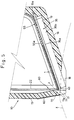
- the upper edge 17a of the opening 17 is disposed lower as compared with conventional staplers. Namely, as shown in Fig. 5, the upper edge 17a of the opening 17 is disposed between the plane of the upper surface of the anvil 40 and the plane of the lower surface of the anvil 40.
- the inner surface of that portion of the front wall 13 disposed above and immediately adjacent to the upper edge 17a of the opening 17 serves as an impingement surface 70 for the staple 1.
- the impingement surface 70 is disposed closer to the mirror 60 than the inner surface of the front wall 13 in the vicinity of the side edges 17b is.
- the impingement surface 70 is inclined downwardly away from the distal end of the anvil 40.
- a gap 71 is formed between the impingement surface 70 and the distal end of the anvil 40, and this gap 71 has a size greater than the diameter of the crown portion 1a of the staple 1, and allows the shaped staple 1 to pass therethrough as later described.
- the projections 22a of the ram 22 are brought into engagement with the crown portion 1a of the foremost staple 1.
- the opposite end portions of the crown portion 1a are bent generally perpendicularly to the central portion thereof through the cooperation of the projections 22a with the anvil 40.
- the distal ends of the pair of legs 1b are moved toward each other, so that they pierce into that portion of the patient to be sutured, and at the time when the shaping (bending) of the foremost staple 1 is completed, the staple 1 has a generally rectangular shape.
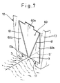
- the suturing operation will now be described in detail with reference to Figs. 5 to 7.
- the operator grasps the casing 10 of the stapler with one hand, and holds a pincette P with the other hand, and the opposed sides of a wound S in the skin are brought toward each other by the pincette to render the wound S generally straight.
- the opposed sides of the wound S are pinched together by the pincette P, and are raised as at X.
- the stapler is so positioned that this raised portion X can be introduced into the openings 17 and 18, as shown in Figs. 5 and 7.
- the front wall 13 of the stapler is kept in a vertical condition, and in this condition the stapler is angularly moved about a vertical axis so as to adjust the position of the stapler so that the wound S can be aligned with a wound S' reflected in the mirror 60 (in which case the actual wound S and the reflected wound S' jointly constitute a common straight line), as shown in Fig. 7.
- the crown portion 1a of the foremost staple 1 is disposed perpendicular to the straight wound S.
- the raised portion X urged by the lower surface of the anvil 40 can be brought into contact with the upper edge 17a of the opening 17. Therefore, by adjusting the position of the stapler so that the center of the upper edge 17a indicated by the distal end of the first reflection portion 60a can be in registry with the wound S, the center of the crown portion 1a of the foremost staple 1 can be brought into registry with the wound S. The operator can make this confirmation, while viewing the wound S obliquely from above this wound.
- the position of the stapler is adjusted in the above manner, so that the foremost staple 1 is disposed perpendicular to the wound S, with the center of the crown portion 1a disposed in registry with the wound S, and in this condition the shaping of the staple 1 is effected, so that a good suturing can be done.
- the shaped staple 1 When the operator, before starting the suturing, operates the stapler for trial purposes to shape the foremost staple 1 without suturing the wound by this shaped staple 1, the shaped staple 1 is pushed by the subsequent staples 1 to vigorously jump from the anvil 40. In this case, however, since the upper edge 17a of the opening 17 is disposed at a level below the upper surface of the anvil 40, the shaped staple impinges on the inclined impingement surface 70, and drops downwardly. Thus, the shaped staple 1 will not jump forwardly, and will not become missing, and therefore this staple can be easily found.
- the upper edge 17a of the opening 17 should be disposed between a position, which is higher than the plane of the upper surface of the anvil 40 by an amount corresponding to the diameter of the crown portion 1a of the staple 1, and the plane of the lower surface of the anvil 40. If the upper edge 17a is disposed at a position higher than the plane of the upper surface of the anvil 40 by an amount exceeding the diameter of the crown portion 1a, the gap between the raised portion X (against which the lower surface of the anvil 40 is held) and the upper edge 17a is large, which results in a possibility that it takes more time to confirm whether or not the center of the upper edge 17a is in registry with the wound S.
- the upper edge 17a if the upper edge 17a is disposed at a level below the plane of the lower surface of the anvil 40, the upper edge 17a urges the raised portion X, so that a gap may be formed between the lower surface of the anvil 40 and the raised portion X.
- the upper edge 17a should preferably be disposed in registry with the plane of the upper surface of the anvil 40, or be disposed below this plane.
- the anvil may be separate from the guide member.
- the mirror may be formed over the generally entire area of the front wall of the casing.
- the means for indicating the center of the upper edge of the opening may be a single line extending upwardly from the center of the upper edge of the opening along the path of movement of the ram.
- the crown portion of the staple does not need to be straight, and may be curved into a generally M-shape.
Landscapes
- Health & Medical Sciences (AREA)
- Engineering & Computer Science (AREA)
- Surgery (AREA)
- Life Sciences & Earth Sciences (AREA)
- Molecular Biology (AREA)
- Biomedical Technology (AREA)
- Heart & Thoracic Surgery (AREA)
- Medical Informatics (AREA)
- Nuclear Medicine, Radiotherapy & Molecular Imaging (AREA)
- Animal Behavior & Ethology (AREA)
- General Health & Medical Sciences (AREA)
- Public Health (AREA)
- Veterinary Medicine (AREA)
- Mechanical Engineering (AREA)
- Surgical Instruments (AREA)
- Portable Nailing Machines And Staplers (AREA)
Claims (8)
- Medizinisches Klammergerät umfassend:(a) ein Gehäuse (10), das eine Vorderwand (13) mit einer Öffnung (17) an einem unteren Endteil hiervon einschließt;(b) Klammerliefermittel (59), die innerhalb dieses Gehäuses gelagert sind, so daß eine Vielzahl von Klammern (1) aneinander angrenzend gehalten werden, wobei dieses Klammerliefermittel nacheinander diese Klammern an eine Position nahe dieser Öffnung liefert, wobei jede dieser Klammern über einen Stegteil (1a) und ein Paar von Schenkeln (1b) verfügt, die jeweils von gegenüberliegenden Enden dieses Stegteils abgehen, und dieser Stegteil einer vordersten dieser Vielzahl von Klammern sich im wesentlichen parallel zu dieser Vorderwand erstreckt;
und(c) Formgebungsmittel (80), die auf diesem Gehäuse angebracht sind, so daß sie die vorderste nahe dieser Öffnung angeordnete Klammer derart formen, daß dieses Paar von Schenkeln dieser vordersten Klammer gegeneinander gebracht wird;dadurch gekennzeichnet, daß ein Spiegel (60) in einer Außenfläche dieser Vorderwand (13) benachbart einem oberen Rand (17a) dieser Öffnung (17) angeordnet ist. - Medizinisches Klammergerät nach Anspruch 1, bei dem dieser obere Rand (17a) dieser Öffnung (17) parallel zu diesem Stegteil (1a) der vordersten Klammer angeordnet ist, wobei die Mitte dieses Stegteils der vordersten Klammer bezüglich der Mitte dieses oberen Randes dieser Öffnung in einer Längsrichtung dieses Stegteils dieser vordersten Klammer ausgerichtet ist.
- Medizinisches Klammergerät nach Anspruch 2, bei dem dieser Spiegel (60) nach oben ein bestimmtes Stück von diesem oberen Rand (17a) dieser Öffnung (17) sich erstreckt.
- Medizinisches Klammergerät nach Anspruch 3, bei dem Anzeigemittel (61) zum Anzeigen der Mitte dieses oberen Randes (17a) dieser Öffnung (17) auf diesem Spiegel (60) vorgesehen sind.
- Medizinisches Klammergerät nach Anspruch 1, bei dem dieses Formgebungsmittel (80) einen Rammbär (22) umfaßt, der innerhalb dieses Gehäuses (10) zur Gleitbewegung längs dieser Vorderwand (13) gelagert ist, wobei ein Betätigungselement (25) auf diesem Gehäuse zur Bewegung dieses Rammbärs nach unten angebracht ist und ein Amboß (40) in einer Bewegungsbahn dieses Rammbärs benachbart dieser öffnung (17) dieser vorderen Wand angeordnet ist, wobei der Stegteil (1a) dieser vordersten Klammer (1) auf diesem Amboß angeordnet wird, und die vorderste Klammer durch das Zusammenwirken des vorrückenden Rammbärs mit diesem Amboß derart geformt wird, daß das Paar von Schenkeln (1b) dieser vordersten Klammer gegeneinander gebracht wird.
- Medizinisches Klammergerät nach Anspruch 5, bei dem dieser obere Rand (17a) dieser Öffnung (17) zwischen einer Position, die höher als die Ebene einer Oberfläche dieses Ambosses (40) um ein Stück ist, das dem Durchmesser dieses Stegteils (1a) dieser Klammer entspricht und einer Position in der Ebene einer unteren Fläche dieses Ambosses angeordnet ist.
- Medizinisches Klammergerät nach Anspruch 6, bei dem diese obere Kante (17a) dieser Öffnung (17) zwischen der Ebene der Oberfläche dieses Ambosses (40) und der Ebene der Unterseite dieses Ambosses angeordnet ist.
- Medizinisches Klammergerät nach Anspruch 7, bei dem dieses Klammernliefermittel (59) Führungsmittel (35) zum Lagern dieser Vielzahl von Klammern (1) aneinander angrenzend umfaßt und ein Beaufschlagungsmittel (50) vorgesehen ist, um diese Vielzahl von Klammern, die auf diesem Führungsmittel gelagert sind, gegen diesen Amboß (40) zu beaufschlagen, wobei dieses Führungsmittel in einer Richtung sich erstreckt, das die Bewegungsbahn dieses Rammbärs (22) vor der Formgebung der vordersten Klammer schneidet, wobei das Paar von Schenkeln (1b) der vordersten Klammer durch eine Innenfläche dieser Vorderwand (13) in der Nachbarschaft der sich gegenüberstehenden Ränder (17b) dieser Öffnung (17) zurückgehalten ist, wobei eine Innenfläche dieses Teils dieser vorderen Wand, die oberhalb und unmittelbar benachbart diesem oberen Rand (17a) dieser Öffnung angeordnet ist, als eine Aufprallfläche (70) für die vorderste Klammer dient, wobei diese Aufprallfläche näher diesem Spiegel (60) angeordnet ist, als diese Innenfläche dieser Vorderwand in der Nachbarschaft der seitlichen Ränder dieser Öffnung ist, so daß ein Spalt (61), der es dem Stegteil (1a) der geformten Klammer ermöglicht, hier durchzugehen, zwischen dieser Aufprallfläche und einem distalen Ende dieses Ambosses geformt wird und diese Aufprallfläche nach unten vom distalen Ende des Ambosses weg geneigt ist.
Applications Claiming Priority (2)
| Application Number | Priority Date | Filing Date | Title |
|---|---|---|---|
| JP38934/91 | 1991-02-12 | ||
| JP03038934A JP3098264B2 (ja) | 1991-02-12 | 1991-02-12 | 医療用ステープラー |
Publications (2)
| Publication Number | Publication Date |
|---|---|
| EP0499355A1 EP0499355A1 (de) | 1992-08-19 |
| EP0499355B1 true EP0499355B1 (de) | 1996-03-27 |
Family
ID=12539059
Family Applications (1)
| Application Number | Title | Priority Date | Filing Date |
|---|---|---|---|
| EP92300127A Expired - Lifetime EP0499355B1 (de) | 1991-02-12 | 1992-01-08 | Medizinisches Klammergerät |
Country Status (4)
| Country | Link |
|---|---|
| US (1) | US5143269A (de) |
| EP (1) | EP0499355B1 (de) |
| JP (1) | JP3098264B2 (de) |
| DE (1) | DE69209341T2 (de) |
Families Citing this family (4)
| Publication number | Priority date | Publication date | Assignee | Title |
|---|---|---|---|---|
| JPH0589609U (ja) * | 1992-05-08 | 1993-12-07 | ミサワホーム株式会社 | パネル下端水切構造 |
| JP4712409B2 (ja) * | 2005-02-28 | 2011-06-29 | マニー株式会社 | 医療用ステープラー |
| JP2006305136A (ja) * | 2005-04-28 | 2006-11-09 | Manii Kk | 医療用ステープラー |
| EP4087498A4 (de) * | 2020-01-09 | 2023-06-07 | Bolder Surgical, LLC | Chirurgisches klammergerät sowie komponenten und verfahren dafür |
Family Cites Families (6)
| Publication number | Priority date | Publication date | Assignee | Title |
|---|---|---|---|---|
| US4349028A (en) * | 1980-10-03 | 1982-09-14 | United States Surgical Corporation | Surgical stapling apparatus having self-contained pneumatic system for completing manually initiated motion sequence |
| US4411378A (en) | 1981-01-28 | 1983-10-25 | Senco Products, Inc. | Disposable surgical stapling instrument having an anvil with coextensive lateral flanges |
| US4619391A (en) | 1984-04-18 | 1986-10-28 | Acme United Corporation | Surgical stapling instrument |
| FR2575375A1 (fr) * | 1984-12-28 | 1986-07-04 | Kahn Raymond | Brosse munie de moyens reflechissants |
| US5022579A (en) * | 1988-08-09 | 1991-06-11 | Matsutani Seisakusho Co., Ltd. | Surgical stapler |
| DE3934698A1 (de) * | 1989-10-18 | 1991-04-25 | Beiersdorf Ag | Chirurgisches geraet zum setzen von wundklammern |
-
1991
- 1991-02-12 JP JP03038934A patent/JP3098264B2/ja not_active Expired - Fee Related
-
1992
- 1992-01-08 DE DE69209341T patent/DE69209341T2/de not_active Expired - Fee Related
- 1992-01-08 EP EP92300127A patent/EP0499355B1/de not_active Expired - Lifetime
- 1992-01-22 US US07/824,105 patent/US5143269A/en not_active Expired - Lifetime
Also Published As
| Publication number | Publication date |
|---|---|
| US5143269A (en) | 1992-09-01 |
| JP3098264B2 (ja) | 2000-10-16 |
| JPH053879A (ja) | 1993-01-14 |
| DE69209341T2 (de) | 1996-08-29 |
| EP0499355A1 (de) | 1992-08-19 |
| DE69209341D1 (de) | 1996-05-02 |
Similar Documents
| Publication | Publication Date | Title |
|---|---|---|
| US4969591A (en) | Surgical stapling system | |
| US4523695A (en) | Surgical stapler | |
| US4316468A (en) | Surgical stapler | |
| EP0000756A1 (de) | Chirurgische Heftmaschine | |
| US4452357A (en) | Surgical stapler | |
| US4619391A (en) | Surgical stapling instrument | |
| US5180092A (en) | Linear surgical stapling instrument | |
| EP0240722B1 (de) | Chirurgisches Klammerinstrument | |
| EP0178940B1 (de) | Chirurgisches Klammernahtgerät | |
| US4470532A (en) | Medical stapling device | |
| GB2130519A (en) | Staple forming and driving machine | |
| US4583670A (en) | Surgical stapling | |
| US4588121A (en) | Belt cartridge for staple forming and driving machine and method | |
| SE464612B (sv) | Staedplatta avsedd att samverka med en kirurgisk haeftapparat | |
| GB2088723A (en) | Multiple clip applier | |
| JPH05208018A (ja) | 外科用ステープル具 | |
| US4570841A (en) | Staple forming and driving machine | |
| EP0436166B1 (de) | Chirurgisches Klammerinstrument | |
| CA1325573C (en) | Staple positioning tab | |
| EP0496493B1 (de) | Medizinisches Klammergerät | |
| US5143269A (en) | Medical stapler | |
| US4364507A (en) | Variable closure surgical stapling apparatus with retractable anvil | |
| EP0040683B1 (de) | Chirurgische Klammervorrichtung | |
| WO1991010400A1 (en) | Ophthalmic stapler | |
| US5265786A (en) | Apparatus for placing surgical staples |
Legal Events
| Date | Code | Title | Description |
|---|---|---|---|
| PUAI | Public reference made under article 153(3) epc to a published international application that has entered the european phase |
Free format text: ORIGINAL CODE: 0009012 |
|
| AK | Designated contracting states |
Kind code of ref document: A1 Designated state(s): DE FR GB |
|
| 17P | Request for examination filed |
Effective date: 19930129 |
|
| 17Q | First examination report despatched |
Effective date: 19950228 |
|
| GRAA | (expected) grant |
Free format text: ORIGINAL CODE: 0009210 |
|
| AK | Designated contracting states |
Kind code of ref document: B1 Designated state(s): DE FR GB |
|
| PG25 | Lapsed in a contracting state [announced via postgrant information from national office to epo] |
Ref country code: FR Effective date: 19960327 |
|
| REF | Corresponds to: |
Ref document number: 69209341 Country of ref document: DE Date of ref document: 19960502 |
|
| EN | Fr: translation not filed | ||
| PLBE | No opposition filed within time limit |
Free format text: ORIGINAL CODE: 0009261 |
|
| 26N | No opposition filed | ||
| REG | Reference to a national code |
Ref country code: GB Ref legal event code: IF02 |
|
| PGFP | Annual fee paid to national office [announced via postgrant information from national office to epo] |
Ref country code: DE Payment date: 20030116 Year of fee payment: 12 |
|
| PG25 | Lapsed in a contracting state [announced via postgrant information from national office to epo] |
Ref country code: DE Free format text: LAPSE BECAUSE OF NON-PAYMENT OF DUE FEES Effective date: 20040803 |
|
| PGFP | Annual fee paid to national office [announced via postgrant information from national office to epo] |
Ref country code: GB Payment date: 20050105 Year of fee payment: 14 |
|
| PG25 | Lapsed in a contracting state [announced via postgrant information from national office to epo] |
Ref country code: GB Free format text: LAPSE BECAUSE OF NON-PAYMENT OF DUE FEES Effective date: 20060108 |
|
| GBPC | Gb: european patent ceased through non-payment of renewal fee |
Effective date: 20060108 |