EP0499559A1 - Procédé et dispositif de contrôle non-destructif par interféromètre holographique d'enceintes en matériau composite - Google Patents
Procédé et dispositif de contrôle non-destructif par interféromètre holographique d'enceintes en matériau composite Download PDFInfo
- Publication number
- EP0499559A1 EP0499559A1 EP92450001A EP92450001A EP0499559A1 EP 0499559 A1 EP0499559 A1 EP 0499559A1 EP 92450001 A EP92450001 A EP 92450001A EP 92450001 A EP92450001 A EP 92450001A EP 0499559 A1 EP0499559 A1 EP 0499559A1
- Authority
- EP
- European Patent Office
- Prior art keywords
- enclosure
- temperature
- liner
- holographic
- image
- Prior art date
- Legal status (The legal status is an assumption and is not a legal conclusion. Google has not performed a legal analysis and makes no representation as to the accuracy of the status listed.)
- Granted
Links
Images


Classifications
-
- G—PHYSICS
- G01—MEASURING; TESTING
- G01B—MEASURING LENGTH, THICKNESS OR SIMILAR LINEAR DIMENSIONS; MEASURING ANGLES; MEASURING AREAS; MEASURING IRREGULARITIES OF SURFACES OR CONTOURS
- G01B11/00—Measuring arrangements characterised by the use of optical techniques
- G01B11/16—Measuring arrangements characterised by the use of optical techniques for measuring the deformation in a solid, e.g. optical strain gauge
- G01B11/161—Measuring arrangements characterised by the use of optical techniques for measuring the deformation in a solid, e.g. optical strain gauge by interferometric means
- G01B11/164—Measuring arrangements characterised by the use of optical techniques for measuring the deformation in a solid, e.g. optical strain gauge by interferometric means by holographic interferometry
-
- F—MECHANICAL ENGINEERING; LIGHTING; HEATING; WEAPONS; BLASTING
- F17—STORING OR DISTRIBUTING GASES OR LIQUIDS
- F17C—VESSELS FOR CONTAINING OR STORING COMPRESSED, LIQUEFIED OR SOLIDIFIED GASES; FIXED-CAPACITY GAS-HOLDERS; FILLING VESSELS WITH, OR DISCHARGING FROM VESSELS, COMPRESSED, LIQUEFIED, OR SOLIDIFIED GASES
- F17C1/00—Pressure vessels, e.g. gas cylinder, gas tank, replaceable cartridge
- F17C1/02—Pressure vessels, e.g. gas cylinder, gas tank, replaceable cartridge involving reinforcing arrangements
- F17C1/04—Protecting sheathings
- F17C1/06—Protecting sheathings built-up from wound-on bands or filamentary material, e.g. wires
-
- G—PHYSICS
- G01—MEASURING; TESTING
- G01B—MEASURING LENGTH, THICKNESS OR SIMILAR LINEAR DIMENSIONS; MEASURING ANGLES; MEASURING AREAS; MEASURING IRREGULARITIES OF SURFACES OR CONTOURS
- G01B9/00—Measuring instruments characterised by the use of optical techniques
- G01B9/02—Interferometers
- G01B9/021—Interferometers using holographic techniques
-
- F—MECHANICAL ENGINEERING; LIGHTING; HEATING; WEAPONS; BLASTING
- F17—STORING OR DISTRIBUTING GASES OR LIQUIDS
- F17C—VESSELS FOR CONTAINING OR STORING COMPRESSED, LIQUEFIED OR SOLIDIFIED GASES; FIXED-CAPACITY GAS-HOLDERS; FILLING VESSELS WITH, OR DISCHARGING FROM VESSELS, COMPRESSED, LIQUEFIED, OR SOLIDIFIED GASES
- F17C2203/00—Vessel construction, in particular walls or details thereof
- F17C2203/06—Materials for walls or layers thereof; Properties or structures of walls or their materials
- F17C2203/0602—Wall structures; Special features thereof
- F17C2203/0604—Liners
-
- F—MECHANICAL ENGINEERING; LIGHTING; HEATING; WEAPONS; BLASTING
- F17—STORING OR DISTRIBUTING GASES OR LIQUIDS
- F17C—VESSELS FOR CONTAINING OR STORING COMPRESSED, LIQUEFIED OR SOLIDIFIED GASES; FIXED-CAPACITY GAS-HOLDERS; FILLING VESSELS WITH, OR DISCHARGING FROM VESSELS, COMPRESSED, LIQUEFIED, OR SOLIDIFIED GASES
- F17C2203/00—Vessel construction, in particular walls or details thereof
- F17C2203/06—Materials for walls or layers thereof; Properties or structures of walls or their materials
- F17C2203/0602—Wall structures; Special features thereof
- F17C2203/0612—Wall structures
- F17C2203/0614—Single wall
- F17C2203/0624—Single wall with four or more layers
-
- F—MECHANICAL ENGINEERING; LIGHTING; HEATING; WEAPONS; BLASTING
- F17—STORING OR DISTRIBUTING GASES OR LIQUIDS
- F17C—VESSELS FOR CONTAINING OR STORING COMPRESSED, LIQUEFIED OR SOLIDIFIED GASES; FIXED-CAPACITY GAS-HOLDERS; FILLING VESSELS WITH, OR DISCHARGING FROM VESSELS, COMPRESSED, LIQUEFIED, OR SOLIDIFIED GASES
- F17C2203/00—Vessel construction, in particular walls or details thereof
- F17C2203/06—Materials for walls or layers thereof; Properties or structures of walls or their materials
- F17C2203/0634—Materials for walls or layers thereof
- F17C2203/0636—Metals
-
- F—MECHANICAL ENGINEERING; LIGHTING; HEATING; WEAPONS; BLASTING
- F17—STORING OR DISTRIBUTING GASES OR LIQUIDS
- F17C—VESSELS FOR CONTAINING OR STORING COMPRESSED, LIQUEFIED OR SOLIDIFIED GASES; FIXED-CAPACITY GAS-HOLDERS; FILLING VESSELS WITH, OR DISCHARGING FROM VESSELS, COMPRESSED, LIQUEFIED, OR SOLIDIFIED GASES
- F17C2203/00—Vessel construction, in particular walls or details thereof
- F17C2203/06—Materials for walls or layers thereof; Properties or structures of walls or their materials
- F17C2203/0634—Materials for walls or layers thereof
- F17C2203/0658—Synthetics
- F17C2203/0663—Synthetics in form of fibers or filaments
- F17C2203/0673—Polymers
-
- F—MECHANICAL ENGINEERING; LIGHTING; HEATING; WEAPONS; BLASTING
- F17—STORING OR DISTRIBUTING GASES OR LIQUIDS
- F17C—VESSELS FOR CONTAINING OR STORING COMPRESSED, LIQUEFIED OR SOLIDIFIED GASES; FIXED-CAPACITY GAS-HOLDERS; FILLING VESSELS WITH, OR DISCHARGING FROM VESSELS, COMPRESSED, LIQUEFIED, OR SOLIDIFIED GASES
- F17C2209/00—Vessel construction, in particular methods of manufacturing
- F17C2209/21—Shaping processes
- F17C2209/2154—Winding
-
- F—MECHANICAL ENGINEERING; LIGHTING; HEATING; WEAPONS; BLASTING
- F17—STORING OR DISTRIBUTING GASES OR LIQUIDS
- F17C—VESSELS FOR CONTAINING OR STORING COMPRESSED, LIQUEFIED OR SOLIDIFIED GASES; FIXED-CAPACITY GAS-HOLDERS; FILLING VESSELS WITH, OR DISCHARGING FROM VESSELS, COMPRESSED, LIQUEFIED, OR SOLIDIFIED GASES
- F17C2221/00—Handled fluid, in particular type of fluid
- F17C2221/03—Mixtures
- F17C2221/031—Air
-
- F—MECHANICAL ENGINEERING; LIGHTING; HEATING; WEAPONS; BLASTING
- F17—STORING OR DISTRIBUTING GASES OR LIQUIDS
- F17C—VESSELS FOR CONTAINING OR STORING COMPRESSED, LIQUEFIED OR SOLIDIFIED GASES; FIXED-CAPACITY GAS-HOLDERS; FILLING VESSELS WITH, OR DISCHARGING FROM VESSELS, COMPRESSED, LIQUEFIED, OR SOLIDIFIED GASES
- F17C2223/00—Handled fluid before transfer, i.e. state of fluid when stored in the vessel or before transfer from the vessel
- F17C2223/03—Handled fluid before transfer, i.e. state of fluid when stored in the vessel or before transfer from the vessel characterised by the pressure level
- F17C2223/036—Very high pressure (>80 bar)
-
- F—MECHANICAL ENGINEERING; LIGHTING; HEATING; WEAPONS; BLASTING
- F17—STORING OR DISTRIBUTING GASES OR LIQUIDS
- F17C—VESSELS FOR CONTAINING OR STORING COMPRESSED, LIQUEFIED OR SOLIDIFIED GASES; FIXED-CAPACITY GAS-HOLDERS; FILLING VESSELS WITH, OR DISCHARGING FROM VESSELS, COMPRESSED, LIQUEFIED, OR SOLIDIFIED GASES
- F17C2250/00—Accessories; Control means; Indicating, measuring or monitoring of parameters
- F17C2250/04—Indicating or measuring of parameters as input values
- F17C2250/0404—Parameters indicated or measured
- F17C2250/0439—Temperature
-
- F—MECHANICAL ENGINEERING; LIGHTING; HEATING; WEAPONS; BLASTING
- F17—STORING OR DISTRIBUTING GASES OR LIQUIDS
- F17C—VESSELS FOR CONTAINING OR STORING COMPRESSED, LIQUEFIED OR SOLIDIFIED GASES; FIXED-CAPACITY GAS-HOLDERS; FILLING VESSELS WITH, OR DISCHARGING FROM VESSELS, COMPRESSED, LIQUEFIED, OR SOLIDIFIED GASES
- F17C2260/00—Purposes of gas storage and gas handling
- F17C2260/04—Reducing risks and environmental impact
- F17C2260/042—Reducing risk of explosion
Definitions
- the present invention relates to the non-destructive testing of enclosures made of composite material wound on a metal liner by holographic interferometry.
- the enclosures made of composite material wound on a metal liner such as for example the tanks used in space technology for the storage of gas under high pressure, consist of a liner, for example made of titanium, which provides a sealing function, coated on the outside with a shell of wound composite material, for example "Kevlar" or carbon, which ensures the mechanical strength, in particular under pressure, of the assembly.
- These reservoirs can have different shapes, spherical or cylindro-spherical for example, with variable diameters of the order of a few tens of centimeters.
- the liner In order to increase the linear operating range of the metal of the liner to bring it as close as possible to that of the fiber of the shell, the liner is subjected to a pre-stress by inflating the tanks beyond the elastic limit of the metal .
- buckles including localized internal folds of the liner forming kinds of blisters whose shape, variable, can cover an area of the order of 50 mm in diameter, and the height of which can reach ten millimeters.
- Buckling can constitute zones of weakness likely to be the cause of ruptures of the liner by crushing during service of the tank, due to the high operating pressure of the latter, of the order of 300 bars per example. Such localized ruptures of the liner inevitably lead to leakage of the gas contained in the tank.
- the task is further complicated by the corrugated external surface of the composite shell, in particular in the vicinity of the poles of the reservoirs, due to the mode of winding of the layers of fibers, such a surface condition making it difficult to correctly position the probe. ultrasonic and uncertain the measurement thereof.
- Holographic interferometry is a well-known optical imaging technique based on the use of coherent light provided by a laser transmitter.
- the output beam of the laser transmitter is separated into a so-called object beam and a so-called reference beam.
- the object beam is directed onto the object to be analyzed and the wave front reflected by the object is collected on a photosensitive recording element or holographic plate, while the reference beam is directed directly onto said holographic plate.
- the so-called double exposure holographic interferometry consists of superimposing on the same holographic plate two holograms of the same object under two very close stress states.
- the first state corresponds to an absence of constraint while, in the second state, the object is subjected to a stress or a constraint which, if there are homogeneity defects in the object, such as faults, cracks or detachments, will lead to a non-homogeneous deformation of the object which will be highlighted by singularities in the set of fringes of the interferogram and which will therefore be easily observable.
- patent FR 84 11450 filed by the Applicant a method of checking by holographic interferometry of the detachment of an inner coating of hollow parts or reservoirs is described, in which the holographic camera is introduced inside the enclosure to be checked and the interferograms are performed under two pressure states of the interior of the enclosure. More specifically, the first interferogram image acquisition is carried out at ambient pressure while the second image acquisition is carried out under vacuum.
- US Patent 3,681,970 describes a method of checking by holographic interferometry live or double exposure, under thermal stress, of a metal structure in order to detect any localized internal faults.
- the patent US Pat. No. 3,976,380 is also known, describing a process for non-destructive testing by holographic interferometry in real time of objects subjected to temperature differences in order to detect any internal faults.
- the application of heat to the object is done by conduction or convection and on the whole mass of the object, because the process aims more precisely at controlling an object of the same material, the aim being to detect anomalies in the homogeneity of the material.
- the present invention aims to apply double exposure holographic interferometry, under thermal stress, to the detection of possible buckling in enclosures made of composite material wound on a metal liner.
- the invention aims in particular to propose a truly industrial process for quickly and remarkably reliable control of the entire wall, in particular of tanks made of composite material wound on a metal liner and, preferably, to carry out such a control systematically. and fully automatic.
- the subject of the invention is a method of non-destructive testing by holographic interferometry of enclosures made of composite material wound on a metal liner, in which two holographic images of the same area to be checked are interfered, taken in two states of different thermal stress, characterized in that the thermal stress is applied homogeneously to the entire liner, inside the enclosure and the interferogram measurement is carried out outside the enclosure, in that that the second image is taken after having brought the liner to a temperature different from that which it had at the time of the taking of the first image and in that the triggering of the second image capture is controlled upon detection, at outside and near the enclosure, a variation, following the change in temperature undergone by the liner, of the external infrared radiation emitted by the enclosure, equal to a predetermined threshold.
- a network of fringes is obtained which accounts for the isodisplacement lines of the zone observed under thermal stress. More specifically, in the event of a defect such as a buckling between liner and composite shell external, existing in the observed area, the isodisplacement lines are disturbed by the fact that the thermal front crossing, from inside to outside, the wall of the controlled enclosure, is slowed down by a phenomenon of thermal resistance due the presence of the pocket formed by said buckling and which behaves like an insulating zone.
- the area of the composite shell located at the level of the buckling deforms or moves differently from the neighboring areas, which the interferogram reveals by local anomalies of the network of fringes.
- the fact of applying the thermal stress, for example using a fluid, inside the enclosure so as to bring the entire mass of the liner, in a homogeneous manner, to the temperatures desired for the intakes of holographic images, allows the holographic camera to embrace in its field a very large surface of the external face of the enclosure, even the observable totality of the enclosure and, thus, in a very reduced number of interferograms which can be reduced to one, to control, quickly and reliably, said observable surface.
- the fluid applied inside the enclosure is preferably air at a temperature higher than the temperature prevailing in the enclosure at the time of the taking of the first image and compatible with the nature of the composite material.
- a fluid at a temperature below the temperature prevailing in the enclosure at the time of the taking of the first image.
- the method is advantageously applicable to the continuous and automatic control of the entire external surface of revolving chambers, of the spherical or cylindro-spherical type for example, by applying a temperature-controlled fluid to the interior of the enclosure. sort of regularly raising or lowering the temperature in the enclosure for a period of time sufficient to operate successively several interferograms each relating to a determined fraction of the external surface of the enclosure, the number of interferograms corresponding to the number of fractions of different surface necessary to cover the whole of said external surface.
- the application of said fluid at a controlled temperature in the enclosure is carried out before the first image of the first interferogram is taken, so as to carry out said taking of the first image at a temperature inside the enclosure. at least slightly higher or lower than room temperature.
- the fluid injected inside the enclosure is for example clean, dusted, dehumidified air, heated to a controlled temperature above room temperature, introduced into the enclosure and immediately extracted at a regular controlled rate.
- the method of the invention makes use of the known technique of taking interferograms in situ, thus making it possible to quickly and entirely automatically control the whole, for example, of a spherical reservoir in six interferograms produced in the space d '' approximately one hour, the various interferograms being able, in the manner also known, to be controlled almost instantaneously, using a video camera placed behind the holographic camera and associated with a video monitor, by an operator who is not necessarily a specialist of holography.
- the invention also relates to an installation for automatic control of enclosures made of composite material wound on a metal liner using the method described above.
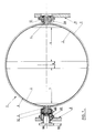
- Figure 1 is shown in diametral section a spherical tank 1, with an external diameter of 650 mm and consisting of a metal liner 2, for example titanium, with a thickness of about 1 mm, on which a a filament envelope 3 was wound, for example in "Kevlar".
- a metal liner 2 for example titanium
- a thickness of about 1 mm on which a a filament envelope 3 was wound, for example in "Kevlar.
- poles two tubular pins 4 and 5, integral with the liner 2, serving to support and to drive the liner in rotation for its winding.
- One of the pins will later be closed, while the other will receive a connection for filling and emptying the tank.
- the buckling likely to appear on the liner 2 can be found essentially in two symmetrical zones identified in 6 and 7 in FIG. 1 and which correspond to the total surface of the sphere reduced by the two caps of the poles corresponding to reinforcement zones d thickness of the liner in line with the trunnions and a small equatorial belt 8.
- the latter corresponds to a connection and welding area of the two hemispheres defining the liner 2, an area which therefore has better rigidity and is not subject to buckling.
- the method of detecting possible buckling of the liner 2 consists, according to the invention, in making two holographic images of the same area to be checked of the sphere 1, taken in two states of stress different from the sphere, interfere.
- a thermal stress exerted according to an embodiment of the invention, by means of a fluid introduced inside the sphere and having a different temperature, higher or lower, at ambient temperature.
- enclosures such as tanks, of revolution shape, spherical or cylindro-spherical for example, for which it is necessary to explore practically the entire surface.
- enclosures such as tanks, of revolution shape, spherical or cylindro-spherical for example, for which it is necessary to explore practically the entire surface.
- external of the enclosure to be checked that is to say presenting the latter under the recording laser beam in different positions in order to cover, step by step, the entire of said surface, but it is quite obvious that if the area to be checked can be fully lit by the laser beam in a single pass, it will not be necessary to move the object to be checked, or even possibly to provide support and presentation means for this object, with controlled movement .
- the invention will be described by using, as the fluid applying a thermal stress, air brought to a determined temperature higher than the ambient temperature, but one could possibly use as fluid another gas, or else a liquid, such than water for example.
- the thermal stress applying fluid can also be used at a temperature below ambient temperature.
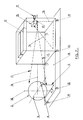
- FIG. 2 represents a spherical reservoir 1 of the type of FIG. 1, supported by a device in the form of a fork 9, the two ends of the fork of which support the pins 4.5 of the sphere 1.
- the center of the sphere is located on the vertical axis 10 of the fork.
- Controlled movement control means are provided for pivoting the axis 10 of the support and presentation device 9 by the desired angle, in one direction or the other.
- one of the supports for the journals 4.5 is arranged to allow the rotation of the sphere 1 around the axis of the journals, in one direction or the other, to the desired degree.
- the sphere 1 is capable of being illuminated by a beam symbolized at 11 from a recording or shooting laser 12.
- the beam from the laser 12 is divided by a splitter 13 into a part constituting the object beam 11 and a part constituting the reference beam 14.
- a holographic camera with a thermoplastic film 15 is placed near the separator 13 so as to see the sphere 1 substantially at the same angle as the object beam 11 whose axis is symbolized at 16 and passes through the center of the sphere 1.
- the camera 15 receives the laser beam reflected by the sphere 1 as well as, at a determined angle, the reference beam 14.
- a viewing camera 17 placed behind the holographic camera makes it possible to collect the image of the interferograms.
- FIG. 2 represents only the parts of the control installation which must be isolated from any vibration and which, therefore, must be mounted on a floating chassis symbolized in 18, itself mounted on shock absorbers symbolized in 19.
- the holographic interferometry technique imposes a great stability of the optical elements and of the object under test and the vibrations are particularly harmful to the production of holograms.
- the role of the shock absorbers 19 is to filter the vibration frequencies above 5 Hz coming from the ground. Similarly, the motorization of the movements of the support device and presentation of the sphere 1 must take this requirement into account and be produced for example with slow damped stops.
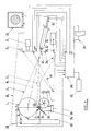
- FIG. 3 is a general diagram of a control installation implementing the method of the invention and incorporating the elements of FIG. 2, isolated from the vibrations of the ground and grouped inside the fictitious frame 20.
- the sphere 1 is represented in FIG. 3 in diametral section with the axis of the poles (4,5) in the plane of the figure.
- the control by holographic interferometry imposes to apply a constraint to the object under test.
- the stress is a thermal stress applied homogeneously to the entire liner and implemented by introducing air at a determined temperature inside the sphere in order to define two states of different constraint allowing to take two holographic shots of the sphere in these two states of constraint.
- Hot air is injected at a controlled temperature and flow, from an injection device symbolized at 21, not integral with the assembly 20 and connected by a flexible pipe 22 to an injection cane 23 inside the sphere 1 arranged in the pin 4 for example.
- the tip of the rod 23 is arranged as a diffuser and so as to collect the air after circulation inside the sphere, this air being evacuated from the sphere by a second pipe. 24 venting.
- a feedback loop 25 produced by a temperature measurement 26 on the air outlet of the sphere makes it possible to regulate (27) the temperature of the air injected by the device 21.
- a microcomputer 28 connected (link 29) to the device 21 and to the feedback loop 25 makes it possible to regulate the temperature and optionally the flow rate of the air injected into the sphere 1 so as to control the temperature rise ramp of air in the sphere as a function of time.
- the optical circuit comprises a recording or shooting laser 12 constituted for example by a pulsed laser of the Ruby type, the beam path of which is materialized by a He-Ne 30 tracer laser.
- the optical assembly is arranged in a folded cavity with an arm reference (14) adaptable in length.
- the holographic recording system consists of the camera with a thermoplastic film 15. This type of camera, well known, realizes in situ and in very short times holograms, thus allowing to proceed in a relatively short time and fully automatically to the production of successive interferograms.
- a read-back laser 31 for example of the He-Ne type identical to the tracer laser 30 and whose wavelength is as close as possible to that of the recording laser 12.
- the read-back beam 31 is substituted for the reference beam 14 using a pivoting mirror 32.
- the viewing camera 17 placed behind the thermoplastic film camera 15 is for example of the video or CCD type and is connected to a control monitor 33.
- the camera 17 makes it possible to collect the image of the interferograms, this image being, parallel to its display on the monitor 33, digitized in an image card placed in the microcomputer 28.
- a printer 34 connected to the microcomputer 28 makes it possible, as will be explained below, to edit a test report for sphere 1.
- a streamer 35 makes it possible to carry out the necessary backups on the microcomputer 28.
- the microcomputer 28 is of course connected to the control means (link 36) for the rotation of the sphere 1 around the axis of the poles or journals 4.5 and to the control means (link 37) for the rotation of the device support and presentation 9 (figure 2) of sphere 1.
- an infrared optical pyrometer 38 connected to the microcomputer 28, is responsible for measuring the infrared radiation of the sphere 1.
- the pyrometer 38 is placed for example at a distance of between 100 and 500 mm from the sphere, in the shadow cone of the latter (relative to the laser illumination).
- FIG. 4 shows in a little more detail a particular embodiment of the optical assembly of the installation of FIG. 2.
- the beam coming from the recording laser 12 is reflected at 45 ° by a deflection mirror 39 towards a separator 13 ', of particular design constituting another characteristic of the method of the invention.
- the object beam 11 at the outlet of the separator 13 'passes through a set 40 of diffuse illumination.
- the reference beam 14 is reflected at 45 ° by a mirror 41, then by reference mirrors at angles of 20 ° respectively fixed 42 and adjustable 43, making it possible to have optical mounting arms of equal length (reference beam 14 / object beam 11), and finally by a last mirror 44 for returning to the thermoplastic film camera 15.
- a single He-Ne laser (30, 31) fulfills the functions of tracing and re-reading respectively of the lasers 30 and 31 of FIG. 3.
- the beam coming from the laser 30, 31 is deflected at 45 ° by a mirror 45 in the direction of a movable return mirror 46 between two positions, one for which it is on the path of the beam from the laser 12 and returns the beam from the He-Ne laser towards the mirror 39 and the other, for which it is outside the path of the laser beam 12.
- the separator 13 ′ is made up, in accordance with the invention, of a movable plate 47 carrying in parallel and side by side a plate of anti-reflective glass 48 allowing the entire beam to pass over the branch reference 14, during proofreading, a separating blade L1 for controlling a "Kevlar" surface, a separating blade L2 for controlling a carbon surface and possibly one or more other separating blades suitable for other composite materials.
- a motor (not shown) allows, under the control of the microcomputer 28, to move the wafer 47 to place in the beam returned by the mirror 39 either the separator L1 or the separator L2, depending on the nature of the composite material , or the proofreading blade 48.
- These blades L1, L2 have different characteristics allowing the reference 14 / object 11 ratio to be adjusted as a function of the type of composite material.
- the blade 48 makes it possible to keep the same optical path on the reference arm 14 by creating, during the re-reading, the same offset linked to the refraction as the blades L1, L2 during the recording.
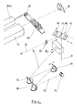
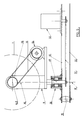
- FIG. 5 schematically illustrates an embodiment of the support means and presentation of the sphere 1.
- the fork-shaped support 9 comprises for example a vertical shaft 49 mounted pivoting in a ball bearing system 50 fixed on the floating frame 18 and driven, at its lower end, by means of a chain transmission 51, by a stepping motor 52 also mounted on the chassis 18, the latter being connected to the ground, symbolized by a fixed chassis 53, by shock absorbers 19.
- the fork 9 also includes a lateral extension supporting a stepping motor 54 for driving, for example by a toothed belt 55, of a pinion 56 wedged on the axis of the journals 4.5 and secured to the sphere 1.
- the motor 52 ensures the controlled rotation of the fork 9 around the vertical axis 10, while the motor 54 ensures the controlled rotation of the sphere 1 around its horizontal axis 4,5.
- the sphere 1 is mounted on the fork 9 as illustrated by way of example in FIG. 1, using ball joints 57 engaged on the pins 4, 5 and retained in cages 58 fixed on the branches of the fork 9.
- One of the pins (4) serves as a passage for the diffusing rod 23.
- the rod 23 which is a simple tube provided with a rounded end pierced with diffusion holes, is arranged at the interior of the duct 24, also introduced into the pin 4, for collecting and evacuating the air outside the enclosure.
- the other journal (5) is secured to a drive hub 59, itself secured to said pinion 56 for driving in rotation of the sphere 1.
- holographic interferometry was implemented in two different states of thermal stress of the sphere 1, said thermal stress being applied, in the present example, by means of a flow of air at a determined temperature injected inside the sphere.
- a second holographic image taken of the same surface part is performed while the sphere is in a second state of thermal stress due to the presence inside said sphere of said air flow at a determined temperature.
- the second holographic image capture makes it possible to obtain an interferogram, the network of fringes of which accounts for disturbances in the isodeplacement lines and thus signals the presence of buckling.
- FIGS. 8 and 9 representing, the first, a regular network of fringes of an interferogram of an area of the healthy sphere, that is to say having no buckling, and, the second, an interferogram whose network of fringes presents singularities indicated by the arrow S, revealing a buckling.
- the interferogram thus obtained makes it possible not only to signal the presence of a buckling (or of several distinct buckling) but also to locate it and circumscribe it precisely inside the surface of the sphere illuminated by the recording laser.
- the first holographic image can be taken at room temperature, that is to say before the injection of hot air inside the sphere.
- room temperature that is to say before the injection of hot air inside the sphere.
- the temperature inside the sphere must be controlled so as to deviate from the ambient temperature without ever exceeding the maximum temperature authorized for the safety of the tank. This maximum temperature is fixed for the types of "Kevlar" or carbon tanks indicated above at 50 ° C.
- the control of the temperature and the flow rate of the air injected into the sphere 1 makes it possible to control the ramp of rise in temperature of the air inside the sphere.
- the second holographic image is taken a few seconds later.
- the triggering of the second image capture is not done as a function of time because it is difficult to assess, from one reservoir to another, the time of propagation of the thermal front through the wall, but as a function of the rise in temperature detected outside of sphere 1 using the pyrometer 38.
- the triggering threshold for the second image can be adopted, for example a temperature rise detected by the pyrometer 38 of 0.1 or 0.2 ° C relative to the time of the taking of the first image.
- the installation makes it possible to automatically and successively repeat the production of such an interferogram for different parts of the external surface of the sphere and during a single rise in temperature of the sphere between the ambient temperature and the maximum tolerated temperature, for example 50 ° C.
- the operating process is as follows. First, the sphere 1 to be checked is put in place on the support and presentation device 9 (FIG. 2). The sphere is positioned from so as to present, as illustrated in FIG. 3, one of its poles or hemispheres (pin 4) towards the recording laser 12. In fact, so that there is no shadow cast on the holographic image, the beam 11 is positioned so that one of its edges substantially tangents the sphere at the level of said pin 4.
- the heating of the sphere 1 is started by sending by the injection device 21 a flow of hot air with controlled flow.
- the air injected into the sphere 1 is uniformly distributed, is recovered by the pipe 24 and, preferably, recycled to the device 21 to limit the heating of the environment, in particular the optical equipment.
- the control of the air temperature and its flow rate, using the devices 21, 27 makes it possible to control the ramp for the temperature rise of the air inside the sphere.
- Figure 7 is a timing diagram illustrating the rise in temperature of the sphere 1 during its control.
- the temperature, detected by the pyrometer 38 will go from the ambient temperature ⁇ a to the equilibrium temperature ⁇ e, substantially lower than the maximum limit temperature ⁇ max tolerable for the composite material. It is during the rectilinear part of the rise in temperature between ⁇ a and ⁇ e that the n interferograms corresponding to n different parts of the external surface of the sphere, necessary and sufficient to cover, will be carried out automatically and under the control of the microcomputer 28. the entire surface to be checked.
- the first interferogram I 1 is defined by the two images taken P 1 and P 2 triggered from the signal supplied by the pyrometer 38.
- the first tap P 1 is triggered from a temperature threshold outside the atmosphere and the second, upon detection by the pyrometer 38 of a temperature rise ⁇ , from the moment of taking p 1 , equal to 0.1 or 0.2 ° C for example.
- the laser 12 fire orders are given by the microcomputer 28, commanding and controlling by software appropriate all the parameters of the installation as well as the control of the heating means of the sphere, of positioning of the latter, of the holographic camera 15 (advance of the thermoplastic film, heating of the latter for its development).
- the microcomputer 28 also controls for each shot or image taking, the tilting of the replay mirror 32 (or the displacement of the mirror 46 in the case of using the assembly of FIG. 4), the lighting of the laser of re-reading 31, the acquisition of the image, via the camera 17, for its storage, then the return to the initial position of the mirrors 32 or 46.
- the sphere 1 can be completely controlled using six interferograms, namely three with the orientation of the sphere shown in FIG. 3, the sphere being simply pivoted twice around the axis of the pins 4,5 and three other interferograms (and two rotations around the 4.5 axis) after 180 ° rotation (command 37) of the 4.5 axis. During these movements the pyrometer 38 and the devices 21 and 25 remain stationary.
- the video monitor 33 makes it possible to view each interferogram.
- the printer 34 makes it possible to edit a report of the check carried out.
- a so-called “manual” function allows the operator, via the microcomputer 28, to access elements of the installation or pieces of the program (development phase, adjustments, return to a particular point set up to date during inspection).
- the slope of the temperature rise ramp of the sphere (figure 7) can be more or less steep: it depends on the temperature range available between ambient temperature and the maximum authorized temperature and on the number of interferograms to be performed during of the same rise in temperature. This is why it is important to provide means for controlling the temperature and the flow rate of the air injected inside the sphere 1.
- the air must also be clean, dusted, dehumidified.
- FIG. 6 illustrates an embodiment of a control box grouping together the elements of the installation of FIG. 3.
- the various mechanical and optical components of the installation are placed in a fairing or box 61 with hatches or doors 62 d 'access for various manipulations or interventions such as in particular the installation and removal of the tank to be checked, the loading of the holographic camera.
- a control and display console is provided and in which the keyboard 63 for dialogue with the microcomputer 28, the video console 64 of the latter, the monitor 33 and the printer 34 are grouped together.
- Such a source can be substituted for the fluid source (21 to 23) described above, without modifications to the other parts of the device illustrated in FIG. 3.
Landscapes
- Engineering & Computer Science (AREA)
- Physics & Mathematics (AREA)
- General Physics & Mathematics (AREA)
- Mechanical Engineering (AREA)
- General Engineering & Computer Science (AREA)
- Holo Graphy (AREA)
- Investigating Strength Of Materials By Application Of Mechanical Stress (AREA)
- Microscoopes, Condenser (AREA)
- Investigating Or Analyzing Materials Using Thermal Means (AREA)
- Investigating Materials By The Use Of Optical Means Adapted For Particular Applications (AREA)
- Length Measuring Devices By Optical Means (AREA)
Abstract
Description
- La présente invention se rapporte au contrôle non destructif d'enceintes en matériau composite bobiné sur liner métallique par interférométrie holographique.
- Les enceintes en matériau composite bobiné sur liner métallique, telles que par exemple les réservoirs utilisés dans la technique spatiale pour le stockage de gaz sous haute pression, sont constituées d'un liner, par exemple en titane, qui assure une fonction d'étanchéité, revêtu extérieurement d'une coque en matériau composite bobiné, par exemple en "Kevlar" ou en carbone, qui assure la tenue mécanique, notamment à la pression, de l'ensemble.
- Ces réservoirs peuvent avoir différentes formes, sphériques ou cylindro-sphériques par exemple, avec des diamètres variables de l'ordre de quelques dizaines de centimètres.
- De façon à augmenter le domaine de fonctionnement linéaire du métal du liner pour le ramener au plus près de celui de la fibre de la coque, on soumet le liner à une pré-contrainte en gonflant les réservoirs au-delà de la limite élastique du métal.
- Celui-ci se déforme de façon irréversible et lorsque la pression interne est supprimée, le liner se trouve comprimé alors que le composite reste légèrement tendu.
- Une telle opération peut entraîner l'apparition de défauts internes localisés, dénommés flambages, du liner.
- Ces flambages dont des replis internes localisés du liner formant des sortes de cloques dont la forme, variable, peut couvrir une surface de l'ordre de 50 mm de diamètre, et dont la hauteur peut atteindre une dizaine de millimètres.
- Les flambages peuvent constituer des zones de fragilité susceptibles d'être à l'origine de ruptures du liner par écrasement en cours de service du réservoir, du fait de la pression d'utilisation importante de ce dernier, de l'ordre de 300 bars par exemple. De telles ruptures localisées du liner entraînent inévitablement des fuites du gaz contenu dans le réservoir.
- Il est donc nécessaire de détecter les flambages, tout au moins ceux dont l'étendue ou les dimensions dépassent un certain seuil, de l'ordre d'une dizaine de millimètres de diamètre.
- Jusqu'à maintenant on a utilisé pour ce faire une méthode par ultrasons. Mais ce type de méthode, bien que non destructif, valable sur des objets de petites dimensions, n'est pas adapté au contrôle d'objets de grande dimensions car il entraîne des temps de contrôle prohibitifs et est délicat à mettre en oeuvre.
- En effet, il faut utiliser une sonde ultrasonore dont l'extrémité, de faible surface, doit être appliquée contre la face externe du réservoir à contrôler, en maintenant la sonde perpendiculaire à la surface auscultée et immobile le temps d'enregistrer les échos de la sonde à chaque application de cette dernière sur ladite surface. On imagine aisément le temps qui serait nécessaire pour ausculter ainsi, de proche en proche, la totalité de la surface externe par exemple d'un réservoir sphérique d'un diamètre externe de l'ordre de 650 mm par exemple.
- La tâche est par ailleurs compliquée par la surface externe ondulée de la coque composite, en particulier au voisinage des pôles des réservoirs, du fait du mode d'enroulement des couches de fibres, un tel état de surface rendant délicat le positionnement correct de la sonde ultrasonore et incertaine la mesure de celle-ci.
- Enfin, l'interprétation des échos de la sonde nécessite un matériel sophistiqué et un personnel spécialisé.
- On pourrait envisager de transposer au contrôle de réservoirs du type ci-dessus, des techniques connues de contrôle non destructif par interférométrie holographique.
- L'interférométrie holographique est une technique d'imagerie optique bien connue fondée sur l'utilisation d'une lumière cohérente fournie par un émetteur laser.
- Le faisceau de sortie de l'émetteur laser est séparé en un faisceau dit objet et en un faisceau dit de référence. Le faisceau objet est dirigé sur l'objet à analyser et le front d'onde réfléchi par l'objet est recueilli sur un élément photosensible d'enregistrement ou plaque holographique, cependant que le faisceau de référence est dirigé directement sur ladite plaque holographique.
- L'interférence entre les deux ondes cohérentes sur la plaque holographique fixe sur celle-ci, du fait des différences des trajets des faisceaux objet et de référence, les différences d'amplitude lumineuse, c'est-à-dire le codage de la phase par modulation d'amplitude, sous forme de franges constituant un hologramme.
- Après développement de la plaque holographique, si l'on éclaire cette dernière sous le même angle que celui du faisceau de référence, avec une lumière monochromatique, on restitue une image en relief de l'objet.
- L'interférométrie holographique dite à double exposition consiste à superposer sur la même plaque holographique deux hologrammes du même objet sous deux états de contrainte très proches. En général, le premier état correspond à une absence de contrainte tandis que, dans le second état, l'objet est soumis à une sollicitation ou une contrainte qui, s'il y a des défauts d'homogénéité dans l'objet, tels que failles, fissures ou décollements, va entraîner une déformation non-homogène de l'objet qui sera mise en évidence par des singularités dans le jeu de franges de l'interférogramme et qui sera donc facilement observable.
- L'interférométrie holographique a déjà fait l'objet de plusieurs applications au contrôle non destructif d'objets ou structures.
- C'est ainsi que par le brevet FR 84 11450 déposé par la Demanderesse, on décrit un procédé de contrôle par interférométrie holographique du décollement d'un revêtement intérieur de pièces creuses ou réservoirs, dans lequel la caméra holographique est introduite à l'intérieur de l'enceinte à contrôler et les interférogrammes sont réalisés sous deux états de pression de l'intérieur de l'enceinte. Plus précisément, la première prise d'image d'interférogramme est effectuée à pression ambiante alors que la seconde prise d'image est effectuée sous dépression.
- Ce procédé malheureusement n'est pas transposable au contrôle de réservoirs du type dont il est question présentement, d'une part, parce que les dimensions de ces réservoirs et leur accès ne permettent pas l'introduction d'une caméra holographique à l'intérieur; et d'autre part, parce qu'il est hors de question de soumettre l'intérieur de ces réservoirs à des dépressions qui auraient tendance à amplifier ou même à créer les flambages. On ne pourrait pas davantage envisager de créer une surpression à l'intérieur des réservoirs car de telles surpressions ne seraient pas de nature à engendrer des variations des lignes d'isodéplacement à la surface externe des réservoirs, décelables et exploitables par interférométrie holographique.
- On a déjà également utilisé l'interférométrie holographique, en direct ou à double exposition, pour le contrôle d'objets soumis à des sollicitations thermiques.
- Le brevet US 3.681.970 décrit un procédé de contrôle par interférométrie holographique en direct ou à double exposition, sous sollicitation thermique, d'une structure métallique en vue de déceler d'éventuel défauts internes localisés.
- A cet effet, on induit localement à l'intérieur de la structure métallique de la chaleur et on observe les variations dimensionnelles de la surface externe. La chaleur, en migrant vers la surface externe de la structure, va être plus ou moins freinée par l'existence par exemple d'une poche d'air et il apparaîtra ainsi à la surface externe des différentiels de température entraînant des différences locales de dilatation détectées par interférométrie holographique.
- Ce procédé, mettant en oeuvre une injection locale de chaleur par induction électrique, ne permet de contrôler qu'une surface très réduite en sorte qu'il est totalement inapplicable, tout comme le contrôle par sonde ultrasonore rappelé plus haut, au contrôle de surfaces importantes.
- On connaît également le brevet US 3.976.380 décrivant un procédé de contrôle non destructif par interférométrie holographique en temps réel d'objets soumis à des différences de température en vue de déceler d'éventuels défauts internes. L'application de la chaleur à l'objet se fait par conduction ou convection et sur toute la masse de l'objet, car le procédé vise plus précisément le contrôle d'un objet d'un même matériau, le but étant de déceler des anomalies dans l'homogénéité du matériau.
- La présente invention vise à appliquer l'interférométrie holographique à double exposition, sous sollicitation thermique, à la détection d'éventuels flambages dans des enceintes en matériau composite bobiné sur liner métallique.
- L'invention vise en particulier à proposer un procédé véritablement industriel permettant de contrôler rapidement et de manière remarquablement fiable la totalité de la paroi notamment de réservoirs en matériau composite bobiné sur liner métallique et, de préférence, d'effectuer un tel contrôle de façon systématique et entièrement automatique.
- A cet effet, l'invention a pour objet un procédé de contrôle non destructif par interférométrie holographique d'enceintes en matériau composite bobiné sur liner métallique, dans lequel on fait interférer deux images holographiques de la même zone à contrôler, prises dans deux états de sollicitation thermique différents, caractérisé en ce que la sollicitation thermique est appliquée de manière homogène à l'ensemble du liner, à l'intérieur de l'enceinte et la prise d'interférogramme est effectuée à l'extérieur de l'enceinte, en ce que la seconde image est prise après avoir porté le liner à une température différente de celle qu'il avait au moment de la prise de la première image et en ce que le déclenchement de la seconde prise d'image est commandé à la détection, à l'extérieur et à proximité de l'enceinte, d'une variation, consécutive à la modification de température subie par le liner, du rayonnement infra-rouge externe émis par l'enceinte, égale à un seuil prédéterminé.
- Par un tel procédé, on obtient un réseau de franges qui rend compte des lignes d'isodéplacement de la zone observée sous la sollicitation thermique. Plus précisément, au droit d'un défaut tel qu'un flambage entre liner et coque composite externe, existant dans la zone observée, les lignes d'isodéplacement sont perturbées par le fait que le front thermique traversant, de l'intérieur vers l'extérieur, la paroi de l'enceinte contrôlée, est freiné par un phénomène de résistance thermique dû à la présence de la poche formée par ledit flambage et qui se comporte comme une zone isolante.
- Il en résulte que la zone de la coque composite située au droit du flambage se déforme ou se déplace différemment des zones avoisinantes, ce que l'interférogramme révèle par des anomalies locales du réseau de franges.
- Le fait d'appliquer la sollicitation thermique, par exemple à l'aide d'un fluide, à l'intérieur de l'enceinte de façon à porter la totalité de la masse du liner, de manière homogène, aux températures désirées pour les prises d'images holographiques, permet à la caméra holographique d'embrasser dans son champ une très large surface de la face externe de l'enceinte, voire la totalité observable de l'enceinte et, ainsi, en un nombre très réduit d'interférogrammes pouvant être ramené à un seul, de contrôler, de manière rapide et fiable, ladite surface observable.
- Le fluide appliqué à l'intérieur de l'enceinte est de préférence de l'air à une température supérieure à la température régnant dans l'enceinte au moment de la prise de la première image et compatible avec la nature du matériau composite. Toutefois, on pourrait envisager l'application d'un fluide à une température inférieure à la température régnant dans l'enceinte au moment de la prise de la première image.
- Le procédé est avantageusement applicable au contrôle en continu et automatique de la totalité de la surface externe d'enceintes de révolution, de type sphérique ou cylindro-sphérique par exemple, en appliquant à l'intérieur de l'enceinte un fluide à température contrôlée en sorte d'élever ou abaisser régulièrement la température dans l'enceinte pendant un laps de temps suffisant pour opérer successivement plusieurs interférogrammes relatifs chacun à une fraction déterminée de la surface externe de l'enceinte, le nombre d'interférogrammes correspondant au nombre de fractions de surface différentes nécessaires pour couvrir la totalité de ladite surface externe.
- De préférence, l'application dudit fluide à température contrôlée dans l'enceinte est réalisée avant la prise de la première image du premier interférogramme, en sorte d'effectuer ladite prise de la première image à une température à l'intérieur de l'enceinte au moins légèrement supérieure ou inférieure à la température ambiante.
- Dans le cas d'une élévation de température à l'intérieur de l'enceinte à contrôler en totalité, cette élévation sera contrôlée en sorte qu'à la fin du dernier interférogramme la température finale de l'enceinte soit substantiellement en deçà du seuil qui serait préjudiciable au matériau composite.
- Le fluide injecté à l'intérieur de l'enceinte est par exemple de l'air propre, dépoussiéré, déshumidifié, chauffé à une température contrôlée supérieure à la température ambiante, introduit dans l'enceinte et extrait aussitôt suivant un débit régulier contrôlé.
- Le procédé de l'invention fait appel à la technique connue de prise d'interférogrammes in situ, permettant ainsi de contrôler de manière rapide et entièrement automatique la totalité, par exemple, d'un réservoir sphérique en six interférogrammes réalisés en l'espace d'une heure environ, les différents interférogrammes pouvant être, à la manière également connue, contrôlée de manière quasi instantanée, à l'aide d'une caméra vidéo disposée derrière la caméra holographique et associée à un moniteur vidéo, par un opérateur non nécessairement spécialiste de l'holographie.
- L'invention concerne également une installation de contrôle automatique d'enceintes en matériau composite bobiné sur liner métallique mettant en oeuvre le procédé exposé ci-dessus.
- D'autres caractéristiques et avantages de l'invention ressortiront de la description qui va suivre d'un mode de réalisation d'une telle installation, description donnée à titre d'exemple uniquement et en regard des dessins annexés sur lesquels :
- Figure 1 est une vue schématique en coupe diamétrale d'un réservoir sphérique en matériau composite bobiné sur liner métallique ;
- Figure 2 est un schéma d'une partie d'une installation de contrôle de réservoirs selon l'invention ;
- Figure 3 est un schéma général d'une installation de contrôle de réservoirs mettant en oeuvre le procédé de l'invention ;
- Figure 4 représente de manière plus détaillée le montage optique des dispositifs lasers suivant un mode de mise en oeuvre particulier de l'invention ;
- Figure 5 est un schéma illustrant un mode de mise en oeuvre de moyens de support et de présentation d'une enceinte en vue de son contrôle ;
- Figure 6 est une vue en perspective schématique d'un module ou caisson de contrôle de réservoir mettant en oeuvre le procédé de l'invention ;
- Figure 7 est un chronogramme illustrant la prise successive d'interférogrammes conformément à l'invention ;
- Figure 8 représente un interférogramme d'une zone saine sans flambage, et
- Figure 9 représente un interférogramme d'une zone à défaut.
- Sur la figure 1 on a représenté en coupe diamétrale un réservoir sphérique 1, d'une diamètre externe de 650 mm et constitué d'un liner métallique 2, par exemple du titane, d'une épaisseur d'environ 1 mm, sur lequel a été bobiné une enveloppe filamentaire 3, par exemple en "Kevlar". En deux endroits diamétralement opposés de la sphère 1, appelés pôles, sont ménagés deux tourillons tubulaires 4 et 5, solidaires du liner 2, servant au support et à l'entrainement en rotation du liner pour son bobinage. L'un des tourillons sera ultérieurement obturé, cependant que l'autre recevra un raccord pour le remplissage et le vidage du réservoir.
- Les flambages susceptibles d'apparaître sur le liner 2 peuvent se rencontrer essentiellement dans deux zones symétriques repérées en 6 et 7 sur la figure 1 et qui correspondent à la surface totale de la sphère diminuée des deux calottes des pôles correspondant à des zones de renforcement d'épaisseur du liner au droit des tourillons et d'une petite ceinture équatoriale 8. Cette dernière correspond à une zone de raccordement et soudage des deux hémisphères définissant le liner 2, zone qui présente de ce fait une meilleure rigidité et n'est pas sujette à flambage.
- Le procédé de détection d'éventuels flambages du liner 2 consiste, selon l'invention, à faire interférer deux images holographiques de la même zone à contrôler de la sphère 1, prises dans deux états de sollicitation différents de la sphère, la sollicitation appliquée étant une contrainte thermique exercée, suivant un mode de mise en oeuvre de l'invention, par l'intermédiaire d'un fluide introduit à l'intérieur de la sphère et ayant une température différente, supérieure ou inférieure, à la température ambiante.
- L'invention va être décrite plus en détail dans une application au contrôle d'enceintes, tels que des réservoirs, de forme de révolution, sphérique ou cylindro-sphérique par exemple, pour lesquelles il est nécessaire d'explorer pratiquement la totalité de la surface externe de l'enceinte à contrôler, c'est-à-dire de présenter cette dernière sous le faisceau laser d'enregistrement dans différentes positions afin de couvrir, de proche en proche, la totalité de ladite surface, mais il est bien évident que si la zone à contrôler peut être en totalité éclairée par le faisceau laser en une seule passe, il ne sera pas nécessaire de déplacer l'objet à contrôler, ni même éventuellement de prévoir des moyens de support et présentation de cet objet, à déplacement contrôlé.
- De même, l'invention sera décrite en utilisant comme fluide applicateur d'une contrainte thermique de l'air porté à une température déterminée supérieure à la température ambiante, mais on pourrait éventuellement utiliser comme fluide un autre gaz, ou bien un liquide, tel que de l'eau par exemple.
- Le fluide applicateur d'une contrainte thermique peut également tout aussi bien être utilisé à une température inférieure à la température ambiante.
- La figure 2 représente un réservoir sphérique 1 du type de la figure 1, supporté par un dispositif en forme de fourche 9 dont les deux extrémités de la fourche supportent les tourillons 4,5 de la sphère 1. Le centre de la sphère se trouve sur l'axe vertical 10 de la fourche.
- Des moyens à commande de déplacement contrôlée sont prévus pour faire pivoter l'axe 10 du dispositif de support et présentation 9 de l'angle désiré, dans un sens ou dans l'autre.
- De même, l'un des supports des tourillons 4,5 est agencé pour permettre l'entrainement en rotation de la sphère 1 autour de l'axe des tourillons, dans un sens ou dans l'autre, du degré désiré.
- La sphère 1 est susceptible d'être illuminée par un faisceau symbolisé en 11 d'un laser d'enregistrement ou de tir 12.
- Le faisceau issu du laser 12 est divisé par une séparatrice 13 en une partie constituant le faisceau objet 11 et une partie constituant le faisceau de référence 14.
- Une caméra holographique à film thermoplastique 15 est placée à proximité de la séparatrice 13 de façon à voir la sphère 1 sensiblement sous le même angle que le faisceau objet 11 dont l'axe est symbolisé en 16 et passe par le centre de la sphère 1. La caméra 15 reçoit le faisceau laser réfléchi par la sphère 1 ainsi que, sous un angle déterminé, le faisceau de référence 14.
- Une caméra de visualisation 17 placée derrière la caméra holographique permet de recueillir l'image des interférogrammes.
- La figure 2 ne représente que les parties de l'installation de contrôle qui doivent être isolées de tout vibration et qui, de ce fait, doivent être montées sur un châssis flottant symbolisé en 18, monté lui-même sur des amortisseurs symbolisés en 19. La technique d'interférométrie holographique impose une grande stabilité des éléments optiques et de l'objet sous test et les vibrations sont particulièrement néfastes à la production d'hologrammes.
- Le rôle des amortisseurs 19 est de filtrer les fréquences vibratoires supérieures à 5 Hz venant du sol. De même, la motorisation des mouvements du dispositif de support et présentation de la sphère 1 doit tenir compte de cet impératif et être réalisée par exemple avec des butées lentes amorties.
- La figure 3 est un schéma général d'une installation de contrôle mettant en oeuvre le procédé de l'invention et incorporant les éléments de la figure 2, isolés des vibrations du sol et regroupés à l'intérieur du cadre fictif 20.
- La sphère 1 est représentée sur la figure 3 en coupe diamétrale avec l'axe des pôles (4,5) dans le plan de la figure.
- Le contrôle par interférométrie holographique impose d'appliquer une contrainte à l'objet sous test.
- Conformément à l'invention, la contrainte est une contrainte thermique appliquée de manière homogène à l'ensemble du liner et mise en oeuvre en introduisant de l'air à une température déterminée à l'intérieur de la sphère en vue de définir deux états de contrainte différents permettant de prendre deux prises de vue holographiques de la sphère dans ces deux états de contrainte.
- De l'air chaud est injecté à une température et à un débit contrôlés, à partir d'un dispositif d'injection symbolisé en 21, non solidaire de l'ensemble 20 et relié par une canalisation souple 22 à une canne 23 d'injection à l'intérieur de la sphère 1 disposée dans le tourillon 4 par exemple. Afin de ne pas perturber l'environnement holographique l'embout de la canne 23 est agencé comme un diffuseur et de façon à recueillir l'air après circulation à l'intérieur de la sphère, cet air étant évacué de la sphère par une seconde canalisation 24 mise à l'atmosphère.
- Une boucle de contre-réaction 25 réalisée par une prise de température 26 sur la sortie de l'air de la sphère permet de réguler (27) la température de l'air injecté par le dispositif 21.
- Un micro-ordinateur 28 relié (liaison 29) au dispositif 21 et à la boucle de contre-réaction 25 permet de réguler la température et éventuellement le débit de l'air injecté dans la sphère 1 de façon à contrôler la rampe de montée en température de l'air dans la sphère en fonction du temps.
- Le circuit optique comprend un laser d'enregistrement ou de tir 12 constitué par exemple par un laser pulsé de type Rubis dont le trajet du faisceau est matérialisé par un laser traceur He-Ne 30. Le montage optique est disposé en cavité repliée avec un bras référence (14) adaptable en longueur.
- Le système d'enregistrement holographique est constitué par la caméra à film thermoplastique 15. Ce type de caméra, bien connu, réalise in situ et dans des temps très courts des hologrammes, permettant ainsi de procéder en un temps relativement court et de manière entièrement automatique à la réalisation d'interférogrammes successifs.
- Un laser de relecture 31, par exemple de type He-Ne identique au laser traceur 30 et dont la longueur d'onde est aussi proche que possible de celle du laser d'enregistrement 12. Le faisceau de relecture 31 est substitué au faisceau de référence 14 à l'aide d'un miroir pivotant 32.
- La caméra de visualisation 17 placée derrière la caméra à film thermoplastique 15 est par exemple du type vidéo ou CCD et est reliée à un moniteur de contrôle 33. La caméra 17 permet de recueillir l'image des interférogrammes, cette image étant, parallèlement à sa visualisation sur le moniteur 33, numérisée dans une carte-image placée dans le micro-ordinateur 28.
- Une imprimante 34 reliée au micro-ordinateur 28 permet, comme il sera expliqué plus loin, d'éditer un procès-verbal de contrôle de la sphère 1.
- Un streamer 35 permet d'effectuer les sauvegardes nécessaires sur le micro-ordinateur 28.
- Le micro-ordinateur 28 est bien entendu relié aux moyens de commande (liaison 36) de la rotation de la sphère 1 autour de l'axe des pôles ou tourillons 4,5 et aux moyens de commande (liaison 37) de la rotation du dispositif de support et présentation 9 (figure 2) de la sphère 1.
- Enfin, un pyromètre optique infrarouge 38, relié au micro-ordinateur 28, est chargé de mesurer le rayonnement infrarouge de la sphère 1.
- Le pyromètre 38 est disposé par exemple à une distance comprise entre 100 et 500 mm de la sphère, dans le cône d'ombre de cette dernière (par rapport à l'illumination laser).
- La figure 4 représente de manière un peu plus détaillée un mode de réalisation particulier du montage optique de l'installation de la figure 2.
- Le faisceau issu du laser d'enregistrement 12 est réfléchi à 45° par un miroir de renvoi 39 vers une séparatrice 13', de conception particulière constituant une autre caractéristique du procédé de l'invention.
- Le faisceau objet 11 à la sortie de la séparatrice 13' traverse un ensemble 40 d'éclairement diffus.
- Le faisceau de référence 14 est réfléchi à 45° par un miroir 41, puis par des miroirs de renvois sous des angles de 20° respectivement fixe 42 et réglable 43, permettant d'avoir des bras de montage optique d'équilongueur (faisceau référence 14/faisceau objet 11), et enfin par un dernier miroir 44 de renvoi vers la caméra à film thermoplastique 15.
- Dans le dispositif représenté sur la figure 4, un seul laser He-Ne (30,31) remplit les fonctions de traçage et de relecture respectivement des lasers 30 et 31 de la figure 3. A cet effet, le faisceau issu du laser 30,31 est dévié à 45° par un miroir 45 en direction d'un miroir 46 de renvoi mobile entre deux positions, l'une, pour laquelle il est sur la trajectoire du faisceau issu du laser 12 et renvoie le faisceau du laser He-Ne vers le miroir 39 et, l'autre, pour laquelle il est en dehors de la trajectoire du faisceau du laser 12.
- La séparatrice 13′ est constituée, conformément à l'invention, d'une plaquette mobile 47 portant en parallèle et côte à côte une lame de verre traitée anti-reflet 48 laissant passer l'intégralité du faisceau sur la branche référence 14, lors de la relecture, une lame séparatrice L1 pour le contrôle d'une surface en "Kevlar", une lame séparatrice L2 pour le contrôle d'une surface en carbone et éventuellement une ou plusieurs autres lames séparatrices adaptées à d'autres matériaux composites. Un moteur (non représenté) permet, sous la commande du micro-ordinateur 28, de déplacer la plaquette 47 pour placer dans le faisceau renvoyé par le miroir 39 soit la séparatrice L1, soit la séparatrice L2, en fonction de la nature du matériau composite, soit la lame de relecture 48. Ces lames L1, L2 ont des caractéristiques différentes permettant de régler le rapport référence 14/objet 11 en fonction du type du matériau composite.
- La lame 48 permet de conserver le même trajet optique sur le bras référence 14 en créant, lors de la relecture, le même déport lié à la réfraction que les lames L1, L2 lors de l'enregistrement.
- La figure 5 illustre schématiquement un mode de réalisation des moyens de support et présentation de la sphère 1.
- Le support en forme de fourche 9 comporte par exemple un arbre vertical 49 monté tourillonnant dans un système de paliers à billes 50 fixé sur le châssis flottant 18 et entraîné, à son extrémité inférieure, par l'intermédiaire d'une transmission à chaîne 51, par un moteur pas à pas 52 également monté sur le châssis 18, ce dernier étant relié au sol, symbolisé par un châssis fixe 53, par des amortisseurs 19.
- La fourche 9 comporte également un prolongement latéral supportant un moteur pas à pas 54 d'entrainement, par exemple par une courroie crantée 55, d'un pignon 56 calé sur l'axe des tourillons 4,5 et solidaire de la sphère 1.
- Le moteur 52 assure la rotation contrôlée de la fourche 9 autour de l'axe vertical 10, cependant que le moteur 54 assure la rotation contrôlée de la sphère 1 autour de son axe horizontal 4,5.
- La sphère 1 est montée sur la fourche 9 comme illustré à titre d'exemple par la figure 1, à l'aide de rotules 57 engagées sur les tourillons 4, 5 et retenues dans des cages 58 fixées sur les branches de la fourche 9.
- L'un des tourillons (4) sert de passage à la canne diffusante 23. Etant donné le diamètre relativement étroit du passage, la canne 23, qui est un simple tube muni d'une extrémité arrondie percée de trous de diffusion, est disposée à l'intérieur du conduit 24, également introduit dans le tourillon 4, de recueil et d'évacuation de l'air hors de l'enceinte.
- L'autre tourillon (5) est solidarisé d'un moyeu d'entrainement 59, lui-même solidarisé dudit pignon 56 d'entrainement en rotation de la sphère 1.
- On va maintenant décrire le principe du procédé selon l'invention de détection d'éventuels flambages du liner de la sphère 1, ainsi que le processus de contrôle automatique et systématique de la sphère à l'aide de l'installation représentée sur la figure 3.
- Il a été dit plus haut que l'interférométrie holographique était mise en oeuvre dans deux états différents de sollicitation thermique de la sphère 1, ladite sollicitation thermique étant appliquée, dans le présent exemple, à l'aide d'un flux d'air à température déterminée injecté à l'intérieur de la sphère.
- Après une première prise d'image holographique de la surface de la sphère 1 illuminée par le laser d'enregistrement 12, la sphère se trouvant dans un premier état de sollicitation thermique, une seconde prise d'image holographique de la même partie de surface est effectuée alors que la sphère se trouve dans un second état de sollicitation thermique du fait de la présence à l'intérieur de la sphère dudit flux d'air à température déterminée.
- S'il existe un flambage dans la zone à contrôler, cela se traduit par la présence d'une poche qui se comporte comme une zone isolante qui va freiner le cheminement, de l'intérieur de la sphère vers l'extérieur, du front thermique engendré par l'apport de calories à l'intérieur de la sphère. Ce freinage du front thermique se traduit par le fait qu'à la surface externe de la sphère, au droit du flambage, apparaîtra un certain gradient de température perturbant localement les lignes d'isodéplacement de ladite surface externe.
- La seconde prise d'image holographique permet d'obtenir un interférogramme dont le réseau de franges rend compte des perturbations des lignes d'isodéplacement et signale ainsi la présence d'un flambage. Pour illustrer ceci on se reportera aux figures 8 et 9 représentant, la première, un réseau régulier de franges d'un interférogramme d'une zone de la sphère saine, c'est-à-dire ne comportant pas de flambage, et, la seconde, un interférogramme dont le réseau de franges présente des singularités indiquées par la flèche S, révélatrices d'un flambage.
- L'interférogramme ainsi obtenu permet non seulement de signaler la présente d'un flambage (ou de plusieurs flambages distincts) mais encore de le situer et le circonscrire précisément à l'intérieur de la surface de la sphère illuminée par le laser d'enregistrement.
- La première prise d'image holographique peut être effectuée à la température ambiante, c'est-à-dire avant l'injection d'air chaud à l'intérieur de la sphère. Cependant, il est préférable, afin d'être indépendant des conditions de température ambiante et de réaliser dans les mêmes conditions une séquence de plusieurs interférogrammes sur la même sphère et au cours d'une même montée en température de la sphère, d'envoyer de l'air à température et débit contrôlés à l'intérieur de la sphère avant la première prise d'image holographique.
- La température à l'intérieur de la sphère doit être contrôlée de manière à s'écarter de la température ambiante sans jamais dépasser la température maximale autorisée pour la sécurité du réservoir. Cette température maximale est fixée, pour les types de réservoirs à "Kevlar" ou carbone indiqués plus haut à 50°C.
- Le contrôle de la température et du débit de l'air injecté dans la sphère 1 permet de contrôler la rampe de montée en température de l'air à l'intérieur de la sphère.
- La seconde prise d'image holographique est effectuée quelques secondes plus tard. Dans la pratique, le déclenchement de la seconde prise d'image ne se fait pas en fonction du temps car il est difficile d'apprécier, d'un réservoir à un autre, le temps de propagation du front thermique à travers la paroi, mais en fonction de l'élévation de la température détectée à l'extérieur de la sphère 1 à l'aide du pyromètre 38.
- On peut adopter comme seuil de déclenchement de la seconde prise d'image, par exemple une élévation de température détectée par le pyromètre 38 de 0,1 ou 0,2 °C par rapport à l'instant de la prise de la première image.
- L'installation dont le principe est illustré par la figure 3 permet de répéter automatiquement et successivement la réalisation d'un tel interférogramme pour différentes parties de la surface externe de la sphère et au cours d'une seule montée en température de la sphère entre la température ambiante et la température maximale tolérée, par exemple 50°C.
- Il y aura en fait autant d'interférogrammes que de parties différentes de la sphère 1 qu'il sera nécessaire d'illuminer par le laser 12 pour couvrir la totalité de la surface à contrôler.
- Le processus opératoire est le suivant. On met d'abord en place la sphère 1 à contrôler sur le dispositif de support et présentation 9 (figure 2). La sphère est positionnée de manière à présenter, comme illustré par la figure 3, l'un de ses pôles ou hémisphères (tourillon 4) vers le laser d'enregistrement 12. En fait, pour qu'il n'y ait pas d'ombre portée sur l'image holographique, le faisceau 11 est positionné de façon que l'un de ses bords tangente sensiblement la sphère au niveau dudit tourillon 4.
- Le chauffage de la sphère 1 est lancé en envoyant par le dispositif d'injection 21 un flux d'air chaud à débit contrôlé. Comme il a été dit plus haut, l'air injecté dans la sphère 1 est diffusé de façon homogène, est récupéré par la canalisation 24 et, de préférence, recyclé vers le dispositif 21 pour limiter l'échauffement de l'environnement, notamment les matériels optiques.
- Le contrôle de la température de l'air et de son débit, à l'aide des dispositifs 21, 27 permet de contrôler la rampe de montée en température de l'air à l'intérieur de la sphère.
- La figure 7 est un chronogramme illustrant la montée en température de la sphère 1 au cours de son contrôle. La température, détectée par le pyromètre 38, va passer de la température ambiante ϑa à la température d'équilibre ϑe, sensiblement inférieure à la température limite maximale ϑmax supportable pour le matériau composite. C'est durant la partie rectiligne de la montée en température entre ϑa et ϑe que seront effectués automatiquement et sous la commande du micro-ordinateur 28 les n interférogrammes correspondant à n parties différentes de la surface externe de la sphère, nécessaires et suffisantes pour couvrir la totalité de la surface à contrôler.
- Sur la figure 7 on n'a représenté que les deux premiers interférogrammes.
- Le premier interférogramme I1 est défini par les deux prises d'images P1 et P2 déclenchées à partir du signal fourni par le pyromètre 38.
- La première prise P1 est déclenchée à partir d'un seuil de température hors de l'ambiance et la seconde, dès la détection par le pyromètre 38 d'une élévation Δϑ de température, à partir de l'instant de la prise p1, égale à 0,1 ou 0,2 °C par exemple.
- Les ordres de tir du laser 12 sont donnés par le micro-ordinateur 28, commandant et contrôlant par un logiciel approprié tous les paramètres de l'installation ainsi que la commande des moyens de chauffage de la sphère, de positionnement de cette dernière, de la caméra holographique 15 (avance du film thermoplastique, chauffage de ce dernier pour son développement).
- Le micro-ordinateur 28 commande également pour chaque tir ou prise d'image, le basculement du miroir de relecture 32 (ou le déplacement du miroir 46 dans le cas de l'utilisation du montage de la figure 4), l'allumage du laser de relecture 31, l'acquisition de l'image, via la caméra 17, pour son stockage, puis le retour en position initiale des miroirs 32 ou 46.
- Sur la figure 7 on a symbolisé en 60 les ordres, donnés entre deux interférogrammes par le micro-ordinateur 28, pour faire avancer le film thermo-plastique et modifier la position de la sphère 1 en vue de l'interférogramme suivant.
- La sphère 1 peut être totalement contrôlée à l'aide de six interférogrammes, à savoir trois avec l'orientation de la sphère représentée sur la figure 3, la sphère étant simplement pivotée deux fois autour de l'axe des tourillons 4,5 et trois autres interférogrammes (et deux rotations autour de l'axe 4,5) après rotation (commande 37) de 180° de l'axe 4,5. Au cours de ces mouvements le pyromètre 38 et les dispositifs 21 et 25 demeurent immobiles.
- Le moniteur vidéo 33 permet de visualiser chaque interférogramme.
- L'imprimante 34 permet d'éditer un procès-verbal du contrôle effectué.
- Une fonction dite "manuelle" permet à l'opérateur, via le micro-ordinateur 28, d'accéder à des éléments de l'installation ou à des morceaux de programme (phase de mise au point, réglages, retour sur un point singulier mis à jour lors du contrôle).
- La pente de la rampe de montée en température de la sphère (figure 7) peut être plus ou moins forte : cela dépend de la plage de température disponible entre la température ambiante et la température maximale autorisée et du nombre d'interférogrammes à réaliser au cours de la même montée en température. C'est pourquoi il est important de prévoir des moyens de contrôle de la température et du débit de l'air injecté à l'intérieur de la sphère 1.
- L'air doit être par ailleurs propre, dépoussiéré, déshumidifié.
- Il serait possible d'injecter de l'air à une température inférieure à la température ambiante pour procéder à la même série d'interférogrammes qu'avec une rampe de montée en température de la sphère, mais avec une rampe descendante de température, dans des conditions analogues de contrôle de débit et température du flux d'air injecté.
- On peut également envisager d'utiliser un autre fluide gazeux que l'air, ou encore un liquide, par exemple de l'eau.
- La figure 6 illustre un mode de réalisation d'un caisson de contrôle regroupant les éléments de l'installation de la figure 3.
- Pour des questions de sécurité de l'opérateur, et pour réaliser la chambre noire nécessaire à l'enregistrement des interférogrammes holographiques, les divers composants mécaniques et optiques de l'installation sont placés dans un carénage ou caisson 61 avec des trappes ou portes 62 d'accès pour les diverses manipulations ou interventions telles que notamment la mise en place et le retrait du réservoir à contrôler, le chargement de la caméra holographique.
- Un pupitre de commande et visualisation est ménagé et où sont regroupés le clavier 63 de dialogue avec le micro-ordinateur 28, la console vidéo 64 de ce dernier, le moniteur 33 et l'imprimante 34.
- Le procédé de l'invention a été décrit en utilisant comme moyen pour appliquer une contrainte thermique au liner 2 un fluide à température contrôlée injecté à l'intérieur de l'enceinte 1, mais on pourrait également appliquer une telle contrainte à l'aide de tout autre moyen propre à créer la différence de température requise tel que, par exemple, une source de rayonnement infra-rouge montée à l'extrémité d'une tige introduite à l'intérieur de l'enceinte.
- Une telle source peut être substituée à la source de fluide (21 à 23) décrite ci-dessus, sans modifications des autres parties du dispositif illustré par la figure 3.
Claims (21)
- Procédé de contrôle non destructif par interférométrie holographique d'enceintes (1) en matériau composite (3) bobiné sur liner métallique (2), dans lequel on fait interférer deux images holographiques de la même zone à contrôler, prises dans deux états de sollicitation thermique différents, caractérisé en ce que la sollicitation thermique est appliquée de manière homogène à l'ensemble du liner, à l'intérieur de l'enceinte et la prise d'interférogramme est effectuée à l'extérieur de l'enceinte, en ce que la seconde image est prise après avoir porté le liner (2) à une température différente de celle qu'il avait au moment de la prise de la première image et en ce que le déclenchement de la seconde prise d'image est commandé à la détection, à l'extérieur et à proximité de l'enceinte (1), d'une variation, consécutive à la modification de température subie par le liner (2), du rayonnement infra-rouge externe émis par l'enceinte, égale à un seuil prédéterminé.
- Procédé suivant la revendication 1, caractérisé en ce que ledit liner (2) est porté à ladite température différente par application à l'intérieur de l'enceinte (1) d'un fluide.
- Procédé suivant la revendication 1, caractérisé en ce que ledit liner (2) est porté à ladite température différente par introduction à l'intérieur de l'enceinte (1) d'une source de rayonnement infra-rouge.
- Procédé suivant les revendications 1 et 2, caractérisé en ce que l'application dudit fluide à l'intérieur de l'enceinte (1) est faite avant le déclenchement de la première prise d'image.
- Procédé suivant les revendications 2 et 4, caractérisé en ce que le déclenchement de la première prise d'image est effectué après que la température de l'enceinte (1) a atteint, à partir de la température ambiante, la partie rectiligne de la rampe, de montée ou de descente de la température de l'enceinte consécutive à l'application dudit fluide à l'intérieur de ladite enceinte.
- Procédé suivant la revendication 5, caractérisé en ce que le fluide appliqué à l'intérieur de l'enceinte (1) est régulé en température et en débit en sorte d'amener la température de l'enceinte (1) entre la température ambiante et une température limite prédéterminée suivant une courbe de montée, ou descente, rectiligne.
- Procédé suivant l'une des revendications 1 à 3, caractérisé en ce qu'après avoir effectué sur une partie déterminée de la surface de l'enceinte (1) un premier interférogramme par la prise desdites première et seconde images, on effectue sur une deuxième partie de ladite surface, un deuxième interférogramme dans des conditions analogues et on renouvelle l'opération autant de fois que nécessaire pour couvrir toute la zone à contrôler de l'enceinte, en sorte d'obtenir au total n interférogrammes.
- Procédé suivant la revendication 6 ou 7, caractérisé en ce que les interférogrammes sont réalisés les uns à la suite des autres, au cours de la même variation de la température de l'enceinte (1).
- Procédé suivant l'une des revendications 6 à 8, caractérisé en ce que pour chaque interférogramme la prise de la seconde image est déclenchée à la détection, à l'extérieur et à proximité de l'enceinte, d'une variation de la température de l'enceinte par rapport à la température à l'instant de la prise de la première image, égale à un seuil prédéterminé.
- Procédé suivant la revendication 9, caractérisé en ce que ledit seuil de variation de température est de l'ordre de 0,1 à 0,2 °C.
- Procédé suivant l'une des revendications 2, 4 à 10, caractérisé en ce que le fluide appliqué à l'intérieur de l'enceinte (1) est de l'air.
- Dispositif pour la mise en oeuvre du procédé selon l'une des revendications 1 à 3, comportant des moyens (9) de support de l'enceinte (1) à contrôler, une caméra holographique (15), un montage optique comprenant un laser d'enregistrement (12), un laser de relecture (31) et des moyens optiques (13,32 ; 40 à 46) pour l'obtention de faisceaux objet (11), de référence (14), et de relecture, caractérisé en ce qu'il comprend, en outre, des moyens (21 à 23) pour faire varier la température du liner (2) de l'enceinte (1), des moyens (38) pour détecter la température de l'enceinte (1) à l'extérieur et à proximité de celle-ci et des moyens (28) reliés à la caméra holographique (15), aux lasers d'enregistrement (12) et de relecture (31) et auxdits moyens (38) de détection de la température de l'enceinte (1) pour commander les prises d'images holographiques.
- Dispositif suivant la revendication 12, caractérisé en ce que lesdits moyens de support de l'enceinte (1) à contrôler sont constitués par un support en forme de fourche (9) aux extrémités de laquelle est fixée de manière amovible l'enceinte (1) suivant un axe de symétrie de cette dernière, des moyens (9a à 9g) étant prévus pour faire pivoter de manière contrôlée, d'une part, l'enceinte autour dudit axe et, d'autre part, ledit support en forme de fourche (9) autour d'un axe perpendiculaire audit axe de l'enceinte (1).
- Dispositif suivant la revendication 12 ou 13, caractérisé en ce que lesdits moyens pour faire varier la température du liner (2) de l'enceinte (1) sont des moyens pour injecter à l'intérieur de l'enceinte un fluide, des moyens (25, 29) étant prévus pour contrôler la température et le débit dudit fluide.
- Dispositif suivant la revendication 14, caractérisé en ce que lesdits moyens pour injecter le fluide à l'intérieur de l'enceinte (1) sont une canne diffusante (23) associée à une canalisation (24) d'évacuation du fluide après circulation à l'intérieur de l'enceinte.
- Dispositif suivant la revendication 15, caractérisé en ce que ladite canalisation (24) d'évacuation du fluide est reliée à un circuit de recyclage du fluide à l'intérieur de l'enceinte (1).
- Dispositif suivant la revendication 12 ou 13, caractérisé en ce que lesdits moyens pour faire varier la température du liner (2) de l'enceinte (1) sont une source de rayonnement infra-rouge.
- Dispositif suivant l'une des revendications 12 à 17, caractérisé en ce que les moyens de support (9) et de positionnement (49 à 56) de l'enceinte (1) à contrôler et les moyens optiques d'enregistrement holographiques sont montés sur un châssis flottant (18) reliés au sol par un système amortisseur (19).
- Dispositif suivant l'une des revendications 12 à 18, caractérisé en ce qu'il comporte, en outre, une caméra de visualisation (17) placée derrière la caméra holographique (15) et reliée à un moniteur vidéo (33).
- Dispositif suivant l'une des revendications 12 à 19, caractérisé en ce que le montage optique comporte une séparatrice constituée d'une plaquette (47) mobile de façon à présenter dans l'axe du faisceau des lasers d'enregistrement (12) et de relecture (31), soit l'une de plusieurs lames séparatrices (L1,L2) de caractéristiques adaptées à la nature du matériau composite de l'enceinte, en vue du réglage du rapport faisceau de référence (14)/ faisceau objet (11), soit une lame (48) laissant passer l'intégralité du faisceau laser sur la branche référence (14), lors de la relecture.
- Dispositif suivant l'une des revendications 12 à 20, caractérisé en ce qu'il comporte un micro-ordinateur (28), équipé d'une imprimante (34) et relié aux divers éléments, composants ou paramètres à commander et/ou contrôler, de la caméra holographique (15), des lasers (12,30,31) et du montage optique, des moyens de support et positionnement (9) de l'enceinte (1), des moyens (23) pour faire varier la température du liner (2) de l'enceinte, des moyens (38) de détection de la température de l'enceinte à l'extérieur de celle-ci, et l'éventuelle caméra de visualisation (17), ledit micro-ordinateur (28) étant programmé pour effectuer automatiquement une séquence complète d'interférogrammes de contrôle de l'enceinte (1).
Applications Claiming Priority (2)
| Application Number | Priority Date | Filing Date | Title |
|---|---|---|---|
| FR9101982A FR2672684B1 (fr) | 1991-02-13 | 1991-02-13 | Procede et dispositif de controle non destructif par interferometrie holographique d'enceintes en materiau composite bobine sur liner metallique. |
| FR9101982 | 1991-02-13 |
Publications (2)
| Publication Number | Publication Date |
|---|---|
| EP0499559A1 true EP0499559A1 (fr) | 1992-08-19 |
| EP0499559B1 EP0499559B1 (fr) | 1998-06-24 |
Family
ID=9409888
Family Applications (1)
| Application Number | Title | Priority Date | Filing Date |
|---|---|---|---|
| EP92450001A Expired - Lifetime EP0499559B1 (fr) | 1991-02-13 | 1992-02-07 | Procédé et dispositif de contrÔle non-destructif par interféromètre holographique d'enceintes en matériau composite |
Country Status (8)
| Country | Link |
|---|---|
| US (1) | US5448352A (fr) |
| EP (1) | EP0499559B1 (fr) |
| JP (1) | JPH05113419A (fr) |
| AT (1) | ATE167737T1 (fr) |
| CA (1) | CA2061097A1 (fr) |
| DE (1) | DE69225986T2 (fr) |
| ES (1) | ES2119805T3 (fr) |
| FR (1) | FR2672684B1 (fr) |
Cited By (1)
| Publication number | Priority date | Publication date | Assignee | Title |
|---|---|---|---|---|
| FR2770639A1 (fr) * | 1997-11-05 | 1999-05-07 | Aerospatiale | Procede de mesure de l'expansion de volume d'un reservoir pressurise et dispositif pour sa mise en oeuvre |
Families Citing this family (8)
| Publication number | Priority date | Publication date | Assignee | Title |
|---|---|---|---|---|
| US5786533A (en) * | 1996-04-17 | 1998-07-28 | Michelin North America, Inc. | Method for analyzing a separation in a deformable structure |
| US20070277919A1 (en) | 2006-05-16 | 2007-12-06 | The Boeing Company | Systems and methods for monitoring automated composite manufacturing processes |
| DE102007040353B3 (de) * | 2007-08-27 | 2009-04-23 | Mähner, Bernward | Vorrichtung zum Prüfen eines Prüfobjekts, insbesondere eines Reifens, mittels eines zerstörungsfreien Messverfahrens |
| RU2580411C1 (ru) * | 2015-01-12 | 2016-04-10 | Федеральное государственное автономное образовательное учреждение высшего образования "Национальный исследовательский Томский политехнический университет" | Тепловизионный дефектоскоп |
| WO2019028465A1 (fr) * | 2017-08-04 | 2019-02-07 | University Of South Florida | Système et procédé sans contact pour détecter des défauts dans le cadre d'un processus de fabrication additive |
| EP3757445A1 (fr) * | 2019-06-24 | 2020-12-30 | Hexagon Ragasco AS | Système et procédé de test de récipients sous pression composites |
| CN113390360B (zh) * | 2021-06-16 | 2022-10-28 | 内蒙古工业大学 | 一种槽式太阳能集热管形变检测方法及装置 |
| CN116678340B (zh) * | 2023-07-28 | 2023-12-12 | 华能澜沧江水电股份有限公司 | 引张线测量装置及其控制方法 |
Citations (9)
| Publication number | Priority date | Publication date | Assignee | Title |
|---|---|---|---|---|
| FR2048189A5 (en) * | 1969-06-03 | 1971-03-19 | Cooptronics Inc | Holographic detection of the deformation - of objects |
| US3644047A (en) * | 1969-05-08 | 1972-02-22 | Gc Optronics Inc | Apparatus and method of simultaneously inspecting a plurality of surfaces of a body by holographic interferometry |
| US3681970A (en) * | 1970-03-09 | 1972-08-08 | G C Optronics Inc | Method of flaw detection using internal heating |
| US3711202A (en) * | 1969-12-08 | 1973-01-16 | Rohr Corp | Holographic testing apparatus |
| US3938889A (en) * | 1974-06-04 | 1976-02-17 | The United States Of America As Represented By The Secretary Of The Air Force | Method and apparatus for measuring linear thermal expansion of polymeric material |
| US3976380A (en) * | 1973-03-13 | 1976-08-24 | Opto-Produkte Ag | Holographic arrangement for testing materials without destroying same |
| GB2018455A (en) * | 1978-04-03 | 1979-10-17 | Goodyear Tire & Rubber | Determining depth location of separations within a tyre |
| GB2021802A (en) * | 1978-05-20 | 1979-12-05 | Rolls Royce | Measuring wall thickness holographically |
| US4506981A (en) * | 1982-10-14 | 1985-03-26 | The B. F. Goodrich Company | Method for detection of blown beads in pneumatic tires |
Family Cites Families (3)
| Publication number | Priority date | Publication date | Assignee | Title |
|---|---|---|---|---|
| US3797938A (en) * | 1972-10-16 | 1974-03-19 | Trw Inc | Optical apparatus for measuring deformation of parabolic antennas |
| FR2568026B1 (fr) * | 1984-07-19 | 1988-09-16 | Aerospatiale | Camera holographique et dispositif de controle non-destructif utilisant une telle camera |
| US4999681A (en) * | 1988-06-24 | 1991-03-12 | Mader David L | Real-time halographic interferometry with a pulsed laser and flicker-free viewing |
-
1991
- 1991-02-13 FR FR9101982A patent/FR2672684B1/fr not_active Expired - Fee Related
-
1992
- 1992-02-07 DE DE69225986T patent/DE69225986T2/de not_active Expired - Fee Related
- 1992-02-07 EP EP92450001A patent/EP0499559B1/fr not_active Expired - Lifetime
- 1992-02-07 ES ES92450001T patent/ES2119805T3/es not_active Expired - Lifetime
- 1992-02-07 AT AT92450001T patent/ATE167737T1/de not_active IP Right Cessation
- 1992-02-12 CA CA002061097A patent/CA2061097A1/fr not_active Abandoned
- 1992-02-13 JP JP4059291A patent/JPH05113419A/ja active Pending
-
1994
- 1994-12-20 US US08/359,859 patent/US5448352A/en not_active Expired - Fee Related
Patent Citations (9)
| Publication number | Priority date | Publication date | Assignee | Title |
|---|---|---|---|---|
| US3644047A (en) * | 1969-05-08 | 1972-02-22 | Gc Optronics Inc | Apparatus and method of simultaneously inspecting a plurality of surfaces of a body by holographic interferometry |
| FR2048189A5 (en) * | 1969-06-03 | 1971-03-19 | Cooptronics Inc | Holographic detection of the deformation - of objects |
| US3711202A (en) * | 1969-12-08 | 1973-01-16 | Rohr Corp | Holographic testing apparatus |
| US3681970A (en) * | 1970-03-09 | 1972-08-08 | G C Optronics Inc | Method of flaw detection using internal heating |
| US3976380A (en) * | 1973-03-13 | 1976-08-24 | Opto-Produkte Ag | Holographic arrangement for testing materials without destroying same |
| US3938889A (en) * | 1974-06-04 | 1976-02-17 | The United States Of America As Represented By The Secretary Of The Air Force | Method and apparatus for measuring linear thermal expansion of polymeric material |
| GB2018455A (en) * | 1978-04-03 | 1979-10-17 | Goodyear Tire & Rubber | Determining depth location of separations within a tyre |
| GB2021802A (en) * | 1978-05-20 | 1979-12-05 | Rolls Royce | Measuring wall thickness holographically |
| US4506981A (en) * | 1982-10-14 | 1985-03-26 | The B. F. Goodrich Company | Method for detection of blown beads in pneumatic tires |
Non-Patent Citations (1)
| Title |
|---|
| APPLIED OPTICS. vol. 21, no. 20, Octobre 1982, NEW YORK US WAGNER ET AL.: 'USING OPTICAL CORRELATION TO MEASURE LEAK RATES IN SEALED PACKAGES.' * |
Cited By (1)
| Publication number | Priority date | Publication date | Assignee | Title |
|---|---|---|---|---|
| FR2770639A1 (fr) * | 1997-11-05 | 1999-05-07 | Aerospatiale | Procede de mesure de l'expansion de volume d'un reservoir pressurise et dispositif pour sa mise en oeuvre |
Also Published As
| Publication number | Publication date |
|---|---|
| DE69225986T2 (de) | 1999-03-25 |
| FR2672684A1 (fr) | 1992-08-14 |
| FR2672684B1 (fr) | 1994-02-04 |
| EP0499559B1 (fr) | 1998-06-24 |
| CA2061097A1 (fr) | 1992-08-14 |
| DE69225986D1 (de) | 1998-07-30 |
| US5448352A (en) | 1995-09-05 |
| ES2119805T3 (es) | 1998-10-16 |
| JPH05113419A (ja) | 1993-05-07 |
| ATE167737T1 (de) | 1998-07-15 |
Similar Documents
| Publication | Publication Date | Title |
|---|---|---|
| EP0499559B1 (fr) | Procédé et dispositif de contrÔle non-destructif par interféromètre holographique d'enceintes en matériau composite | |
| FR2511523A1 (fr) | Procede et dispositif pour pratiquer, verifier et regler la position d'une serie de trous dans un element | |
| WO1996041697A1 (fr) | Installation pour travailler une zone d'un tube au moyen d'un faisceau laser et application aux tubes d'une canalisation sur une barge de pose en mer ou de recuperation de cette canalisation | |
| JPH0521420B2 (fr) | ||
| FR2542125A1 (fr) | Appareil et procede pour verifier les soudures des bouchons d'extremite de barres de combustible pour reacteur nucleaire | |
| WO2013139718A1 (fr) | Procédé et dispositif de contrôle d'un matériau composite par ultrasons laser | |
| FR2631731A1 (fr) | Ensemble d'entrainement de support de sonde pour la detection de defauts dans des tubes, notamment des tubes de generateurs de vapeur | |
| EP0310526B1 (fr) | Procédé et dispositif de contrôle de la pression régnant dans une enceinte ou capacité | |
| EP0234982B1 (fr) | Dispositif de contrôle non-destructif d'une pièce par holographie optique | |
| FR2897158A1 (fr) | Dispositif et procede manuel de positionnement d'une source de radiographie par rayons gamma d'au moins une soudure d'une tubulure. | |
| EP0965038B1 (fr) | Procede d'examen photothermique d'une piece | |
| FR2499718A1 (fr) | Procede et dispositif pour la detection des defauts de surface des pieces mecaniques, en particulier des pieces a surface courbe | |
| EP0248705B1 (fr) | Appareil d'irradiation pour circuits électroniques | |
| EP1099947A2 (fr) | Procédé et dispositif pour faire un essai optique d'un pneu | |
| EP0668493B1 (fr) | Procédé et dispositif de contrÔle de nids d'abeilles à l'aide de fibres optiques | |
| FR2568026A1 (fr) | Camera holographique et dispositif de controle non-destructif utilisant une telle camera | |
| EP3781902B1 (fr) | Dispositif de mesure pour déterminer l'épaisseur d'une couche d'un matériau | |
| FR2570502A1 (fr) | Installation pour le controle ultrasonore de pieces, et dispositif pour balayer une surface de la piece a controler | |
| EP0056554B1 (fr) | Dispositif de contrôle en service de l'intégrité des soudures des structures off-shore | |
| FR2908674A1 (fr) | Dispositif de nettoyage et de depollution d'un objet a environnement confine non etanche limite par une paroi a membrane souple | |
| EP0329554B1 (fr) | Procédé et installation de détection de crayons non étanches dans un assemblage de combustible nucléaire | |
| FR2591341A1 (fr) | Technique de detection de defauts optiques sur ligne de production de verre | |
| FR2515347A1 (fr) | Procede de detection et de localisation de micro-fuites dans une paroi et notamment dans la barriere secondaire des cuves de methaniers | |
| EP3182097B1 (fr) | Dispositif de contrôle par tomographie en cohérence optique notamment dans un congé d'une pièce composite | |
| FR2908875A1 (fr) | Dispositif de mesure sans contact de la deformation d'une membrane, et applications |
Legal Events
| Date | Code | Title | Description |
|---|---|---|---|
| PUAI | Public reference made under article 153(3) epc to a published international application that has entered the european phase |
Free format text: ORIGINAL CODE: 0009012 |
|
| AK | Designated contracting states |
Kind code of ref document: A1 Designated state(s): AT BE CH DE ES FR GB IT LI LU NL |
|
| 17P | Request for examination filed |
Effective date: 19930129 |
|
| 17Q | First examination report despatched |
Effective date: 19930701 |
|
| APCB | Communication from the board of appeal sent |
Free format text: ORIGINAL CODE: EPIDOS OBAPE |
|
| APCB | Communication from the board of appeal sent |
Free format text: ORIGINAL CODE: EPIDOS OBAPE |
|
| APCB | Communication from the board of appeal sent |
Free format text: ORIGINAL CODE: EPIDOS OBAPE |
|
| APCB | Communication from the board of appeal sent |
Free format text: ORIGINAL CODE: EPIDOS OBAPE |
|
| APCB | Communication from the board of appeal sent |
Free format text: ORIGINAL CODE: EPIDOS OBAPE |
|
| APCB | Communication from the board of appeal sent |
Free format text: ORIGINAL CODE: EPIDOS OBAPE |
|
| APAB | Appeal dossier modified |
Free format text: ORIGINAL CODE: EPIDOS NOAPE |
|
| GRAG | Despatch of communication of intention to grant |
Free format text: ORIGINAL CODE: EPIDOS AGRA |
|
| GRAG | Despatch of communication of intention to grant |
Free format text: ORIGINAL CODE: EPIDOS AGRA |
|
| GRAH | Despatch of communication of intention to grant a patent |
Free format text: ORIGINAL CODE: EPIDOS IGRA |
|
| GRAH | Despatch of communication of intention to grant a patent |
Free format text: ORIGINAL CODE: EPIDOS IGRA |
|
| GRAA | (expected) grant |
Free format text: ORIGINAL CODE: 0009210 |
|
| AK | Designated contracting states |
Kind code of ref document: B1 Designated state(s): AT BE CH DE ES FR GB IT LI LU NL |
|
| PG25 | Lapsed in a contracting state [announced via postgrant information from national office to epo] |
Ref country code: NL Free format text: LAPSE BECAUSE OF FAILURE TO SUBMIT A TRANSLATION OF THE DESCRIPTION OR TO PAY THE FEE WITHIN THE PRESCRIBED TIME-LIMIT Effective date: 19980624 Ref country code: AT Free format text: LAPSE BECAUSE OF FAILURE TO SUBMIT A TRANSLATION OF THE DESCRIPTION OR TO PAY THE FEE WITHIN THE PRESCRIBED TIME-LIMIT Effective date: 19980624 |
|
| REF | Corresponds to: |
Ref document number: 167737 Country of ref document: AT Date of ref document: 19980715 Kind code of ref document: T |
|
| REG | Reference to a national code |
Ref country code: CH Ref legal event code: EP |
|
| REF | Corresponds to: |
Ref document number: 69225986 Country of ref document: DE Date of ref document: 19980730 |
|
| GBT | Gb: translation of ep patent filed (gb section 77(6)(a)/1977) |
Effective date: 19980911 |
|
| REG | Reference to a national code |
Ref country code: ES Ref legal event code: FG2A Ref document number: 2119805 Country of ref document: ES Kind code of ref document: T3 |
|
| NLV1 | Nl: lapsed or annulled due to failure to fulfill the requirements of art. 29p and 29m of the patents act | ||
| PGFP | Annual fee paid to national office [announced via postgrant information from national office to epo] |
Ref country code: GB Payment date: 19990125 Year of fee payment: 8 |
|
| PG25 | Lapsed in a contracting state [announced via postgrant information from national office to epo] |
Ref country code: LU Free format text: LAPSE BECAUSE OF NON-PAYMENT OF DUE FEES Effective date: 19990207 |
|
| PGFP | Annual fee paid to national office [announced via postgrant information from national office to epo] |
Ref country code: ES Payment date: 19990222 Year of fee payment: 8 |
|
| PG25 | Lapsed in a contracting state [announced via postgrant information from national office to epo] |
Ref country code: LI Free format text: LAPSE BECAUSE OF NON-PAYMENT OF DUE FEES Effective date: 19990228 Ref country code: CH Free format text: LAPSE BECAUSE OF NON-PAYMENT OF DUE FEES Effective date: 19990228 |
|
| PGFP | Annual fee paid to national office [announced via postgrant information from national office to epo] |
Ref country code: BE Payment date: 19990316 Year of fee payment: 8 |
|
| PGFP | Annual fee paid to national office [announced via postgrant information from national office to epo] |
Ref country code: DE Payment date: 19990406 Year of fee payment: 8 |
|
| PLBE | No opposition filed within time limit |
Free format text: ORIGINAL CODE: 0009261 |
|
| 26N | No opposition filed | ||
| REG | Reference to a national code |
Ref country code: CH Ref legal event code: PL |
|
| PG25 | Lapsed in a contracting state [announced via postgrant information from national office to epo] |
Ref country code: GB Free format text: LAPSE BECAUSE OF NON-PAYMENT OF DUE FEES Effective date: 20000207 |
|
| PG25 | Lapsed in a contracting state [announced via postgrant information from national office to epo] |
Ref country code: ES Free format text: LAPSE BECAUSE OF NON-PAYMENT OF DUE FEES Effective date: 20000208 |
|
| PG25 | Lapsed in a contracting state [announced via postgrant information from national office to epo] |
Ref country code: BE Free format text: LAPSE BECAUSE OF NON-PAYMENT OF DUE FEES Effective date: 20000228 |
|
| PGFP | Annual fee paid to national office [announced via postgrant information from national office to epo] |
Ref country code: FR Payment date: 20000228 Year of fee payment: 9 |
|
| BERE | Be: lapsed |
Owner name: AEROSPATIALE SOC. NATIONALE INDUSTRIELLE Effective date: 20000228 |
|
| GBPC | Gb: european patent ceased through non-payment of renewal fee |
Effective date: 20000207 |
|
| PG25 | Lapsed in a contracting state [announced via postgrant information from national office to epo] |
Ref country code: DE Free format text: LAPSE BECAUSE OF NON-PAYMENT OF DUE FEES Effective date: 20001201 |
|
| PG25 | Lapsed in a contracting state [announced via postgrant information from national office to epo] |
Ref country code: FR Free format text: LAPSE BECAUSE OF NON-PAYMENT OF DUE FEES Effective date: 20011031 |
|
| REG | Reference to a national code |
Ref country code: ES Ref legal event code: FD2A Effective date: 20010910 |
|
| REG | Reference to a national code |
Ref country code: FR Ref legal event code: ST |
|
| PG25 | Lapsed in a contracting state [announced via postgrant information from national office to epo] |
Ref country code: IT Free format text: LAPSE BECAUSE OF NON-PAYMENT OF DUE FEES;WARNING: LAPSES OF ITALIAN PATENTS WITH EFFECTIVE DATE BEFORE 2007 MAY HAVE OCCURRED AT ANY TIME BEFORE 2007. THE CORRECT EFFECTIVE DATE MAY BE DIFFERENT FROM THE ONE RECORDED. Effective date: 20050207 |
|
| APAH | Appeal reference modified |
Free format text: ORIGINAL CODE: EPIDOSCREFNO |