EP0499559B1 - Procédé et dispositif de contrÔle non-destructif par interféromètre holographique d'enceintes en matériau composite - Google Patents
Procédé et dispositif de contrÔle non-destructif par interféromètre holographique d'enceintes en matériau composite Download PDFInfo
- Publication number
- EP0499559B1 EP0499559B1 EP92450001A EP92450001A EP0499559B1 EP 0499559 B1 EP0499559 B1 EP 0499559B1 EP 92450001 A EP92450001 A EP 92450001A EP 92450001 A EP92450001 A EP 92450001A EP 0499559 B1 EP0499559 B1 EP 0499559B1
- Authority
- EP
- European Patent Office
- Prior art keywords
- enclosure
- temperature
- liner
- holographic
- image
- Prior art date
- Legal status (The legal status is an assumption and is not a legal conclusion. Google has not performed a legal analysis and makes no representation as to the accuracy of the status listed.)
- Expired - Lifetime
Links
Images


Classifications
-
- G—PHYSICS
- G01—MEASURING; TESTING
- G01B—MEASURING LENGTH, THICKNESS OR SIMILAR LINEAR DIMENSIONS; MEASURING ANGLES; MEASURING AREAS; MEASURING IRREGULARITIES OF SURFACES OR CONTOURS
- G01B11/00—Measuring arrangements characterised by the use of optical techniques
- G01B11/16—Measuring arrangements characterised by the use of optical techniques for measuring the deformation in a solid, e.g. optical strain gauge
- G01B11/161—Measuring arrangements characterised by the use of optical techniques for measuring the deformation in a solid, e.g. optical strain gauge by interferometric means
- G01B11/164—Measuring arrangements characterised by the use of optical techniques for measuring the deformation in a solid, e.g. optical strain gauge by interferometric means by holographic interferometry
-
- F—MECHANICAL ENGINEERING; LIGHTING; HEATING; WEAPONS; BLASTING
- F17—STORING OR DISTRIBUTING GASES OR LIQUIDS
- F17C—VESSELS FOR CONTAINING OR STORING COMPRESSED, LIQUEFIED OR SOLIDIFIED GASES; FIXED-CAPACITY GAS-HOLDERS; FILLING VESSELS WITH, OR DISCHARGING FROM VESSELS, COMPRESSED, LIQUEFIED, OR SOLIDIFIED GASES
- F17C1/00—Pressure vessels, e.g. gas cylinder, gas tank, replaceable cartridge
- F17C1/02—Pressure vessels, e.g. gas cylinder, gas tank, replaceable cartridge involving reinforcing arrangements
- F17C1/04—Protecting sheathings
- F17C1/06—Protecting sheathings built-up from wound-on bands or filamentary material, e.g. wires
-
- G—PHYSICS
- G01—MEASURING; TESTING
- G01B—MEASURING LENGTH, THICKNESS OR SIMILAR LINEAR DIMENSIONS; MEASURING ANGLES; MEASURING AREAS; MEASURING IRREGULARITIES OF SURFACES OR CONTOURS
- G01B9/00—Measuring instruments characterised by the use of optical techniques
- G01B9/02—Interferometers
- G01B9/021—Interferometers using holographic techniques
-
- F—MECHANICAL ENGINEERING; LIGHTING; HEATING; WEAPONS; BLASTING
- F17—STORING OR DISTRIBUTING GASES OR LIQUIDS
- F17C—VESSELS FOR CONTAINING OR STORING COMPRESSED, LIQUEFIED OR SOLIDIFIED GASES; FIXED-CAPACITY GAS-HOLDERS; FILLING VESSELS WITH, OR DISCHARGING FROM VESSELS, COMPRESSED, LIQUEFIED, OR SOLIDIFIED GASES
- F17C2203/00—Vessel construction, in particular walls or details thereof
- F17C2203/06—Materials for walls or layers thereof; Properties or structures of walls or their materials
- F17C2203/0602—Wall structures; Special features thereof
- F17C2203/0604—Liners
-
- F—MECHANICAL ENGINEERING; LIGHTING; HEATING; WEAPONS; BLASTING
- F17—STORING OR DISTRIBUTING GASES OR LIQUIDS
- F17C—VESSELS FOR CONTAINING OR STORING COMPRESSED, LIQUEFIED OR SOLIDIFIED GASES; FIXED-CAPACITY GAS-HOLDERS; FILLING VESSELS WITH, OR DISCHARGING FROM VESSELS, COMPRESSED, LIQUEFIED, OR SOLIDIFIED GASES
- F17C2203/00—Vessel construction, in particular walls or details thereof
- F17C2203/06—Materials for walls or layers thereof; Properties or structures of walls or their materials
- F17C2203/0602—Wall structures; Special features thereof
- F17C2203/0612—Wall structures
- F17C2203/0614—Single wall
- F17C2203/0624—Single wall with four or more layers
-
- F—MECHANICAL ENGINEERING; LIGHTING; HEATING; WEAPONS; BLASTING
- F17—STORING OR DISTRIBUTING GASES OR LIQUIDS
- F17C—VESSELS FOR CONTAINING OR STORING COMPRESSED, LIQUEFIED OR SOLIDIFIED GASES; FIXED-CAPACITY GAS-HOLDERS; FILLING VESSELS WITH, OR DISCHARGING FROM VESSELS, COMPRESSED, LIQUEFIED, OR SOLIDIFIED GASES
- F17C2203/00—Vessel construction, in particular walls or details thereof
- F17C2203/06—Materials for walls or layers thereof; Properties or structures of walls or their materials
- F17C2203/0634—Materials for walls or layers thereof
- F17C2203/0636—Metals
-
- F—MECHANICAL ENGINEERING; LIGHTING; HEATING; WEAPONS; BLASTING
- F17—STORING OR DISTRIBUTING GASES OR LIQUIDS
- F17C—VESSELS FOR CONTAINING OR STORING COMPRESSED, LIQUEFIED OR SOLIDIFIED GASES; FIXED-CAPACITY GAS-HOLDERS; FILLING VESSELS WITH, OR DISCHARGING FROM VESSELS, COMPRESSED, LIQUEFIED, OR SOLIDIFIED GASES
- F17C2203/00—Vessel construction, in particular walls or details thereof
- F17C2203/06—Materials for walls or layers thereof; Properties or structures of walls or their materials
- F17C2203/0634—Materials for walls or layers thereof
- F17C2203/0658—Synthetics
- F17C2203/0663—Synthetics in form of fibers or filaments
- F17C2203/0673—Polymers
-
- F—MECHANICAL ENGINEERING; LIGHTING; HEATING; WEAPONS; BLASTING
- F17—STORING OR DISTRIBUTING GASES OR LIQUIDS
- F17C—VESSELS FOR CONTAINING OR STORING COMPRESSED, LIQUEFIED OR SOLIDIFIED GASES; FIXED-CAPACITY GAS-HOLDERS; FILLING VESSELS WITH, OR DISCHARGING FROM VESSELS, COMPRESSED, LIQUEFIED, OR SOLIDIFIED GASES
- F17C2209/00—Vessel construction, in particular methods of manufacturing
- F17C2209/21—Shaping processes
- F17C2209/2154—Winding
-
- F—MECHANICAL ENGINEERING; LIGHTING; HEATING; WEAPONS; BLASTING
- F17—STORING OR DISTRIBUTING GASES OR LIQUIDS
- F17C—VESSELS FOR CONTAINING OR STORING COMPRESSED, LIQUEFIED OR SOLIDIFIED GASES; FIXED-CAPACITY GAS-HOLDERS; FILLING VESSELS WITH, OR DISCHARGING FROM VESSELS, COMPRESSED, LIQUEFIED, OR SOLIDIFIED GASES
- F17C2221/00—Handled fluid, in particular type of fluid
- F17C2221/03—Mixtures
- F17C2221/031—Air
-
- F—MECHANICAL ENGINEERING; LIGHTING; HEATING; WEAPONS; BLASTING
- F17—STORING OR DISTRIBUTING GASES OR LIQUIDS
- F17C—VESSELS FOR CONTAINING OR STORING COMPRESSED, LIQUEFIED OR SOLIDIFIED GASES; FIXED-CAPACITY GAS-HOLDERS; FILLING VESSELS WITH, OR DISCHARGING FROM VESSELS, COMPRESSED, LIQUEFIED, OR SOLIDIFIED GASES
- F17C2223/00—Handled fluid before transfer, i.e. state of fluid when stored in the vessel or before transfer from the vessel
- F17C2223/03—Handled fluid before transfer, i.e. state of fluid when stored in the vessel or before transfer from the vessel characterised by the pressure level
- F17C2223/036—Very high pressure (>80 bar)
-
- F—MECHANICAL ENGINEERING; LIGHTING; HEATING; WEAPONS; BLASTING
- F17—STORING OR DISTRIBUTING GASES OR LIQUIDS
- F17C—VESSELS FOR CONTAINING OR STORING COMPRESSED, LIQUEFIED OR SOLIDIFIED GASES; FIXED-CAPACITY GAS-HOLDERS; FILLING VESSELS WITH, OR DISCHARGING FROM VESSELS, COMPRESSED, LIQUEFIED, OR SOLIDIFIED GASES
- F17C2250/00—Accessories; Control means; Indicating, measuring or monitoring of parameters
- F17C2250/04—Indicating or measuring of parameters as input values
- F17C2250/0404—Parameters indicated or measured
- F17C2250/0439—Temperature
-
- F—MECHANICAL ENGINEERING; LIGHTING; HEATING; WEAPONS; BLASTING
- F17—STORING OR DISTRIBUTING GASES OR LIQUIDS
- F17C—VESSELS FOR CONTAINING OR STORING COMPRESSED, LIQUEFIED OR SOLIDIFIED GASES; FIXED-CAPACITY GAS-HOLDERS; FILLING VESSELS WITH, OR DISCHARGING FROM VESSELS, COMPRESSED, LIQUEFIED, OR SOLIDIFIED GASES
- F17C2260/00—Purposes of gas storage and gas handling
- F17C2260/04—Reducing risks and environmental impact
- F17C2260/042—Reducing risk of explosion
Definitions
- the present invention relates to control not destructive of composite material enclosures wound on liner metallic by holographic interferometry.
- Composite material enclosures wound on liner metallic such as for example the tanks used in space technology for high gas storage pressure, consist of a liner, for example made of titanium, which provides a sealing function, coated on the outside of a shell of wound composite material, for example in "Kevlar” or carbon, which provides mechanical strength, including pressure, of the whole.
- These tanks can have different shapes, spherical or cylindro-spherical for example, with variable diameters of the order of a few tens of centimeters.
- the liner In order to increase the linear operating range of the metal of the liner to bring it closer to that of the fiber of the hull, the liner is subjected to a pre-stress in inflating the tanks beyond the elastic limit of the metal.
- buckling including localized internal folds of the liner forming kinds of blisters whose variable shape can cover an area of the order of 50 mm in diameter, and of which the height can reach ten millimeters.
- Buckling can be fragile areas likely to cause liner ruptures by crushing during tank service, due to significant use pressure of the latter, of the order of 300 bars for example. Such localized ruptures of the liner inevitably lead to leakage of the gas contained in the tank.
- the task is further complicated by the surface corrugated external of the composite shell, in particular at proximity of the poles of the reservoirs, due to the mode winding layers of fibers, such a surface condition making it difficult to correctly position the probe ultrasonic and uncertain the measurement thereof.
- Holographic interferometry is a technique well-known optical imaging based on the use of a coherent light provided by a laser transmitter.
- the laser transmitter output beam is separated into one said object beam and into a reference beam.
- the object beam is directed at the object to be analyzed and the front wave reflected by the object is collected on an element photosensitive recording or holographic plate, however that the reference beam is directed directly on said holographic plate.
- Holographic interferometry known as double exposure consists of superimposing on the same holographic plate two holograms of the same object under two very constrained states relatives.
- the first state corresponds to an absence of constraint while, in the second state, the object is subject to a solicitation or a constraint which, if there are homogeneity in the object, such as faults, cracks or detachments, will cause a non-homogeneous deformation of the object which will be highlighted by singularities in the set of fringes of the interferogram and which will therefore easily observable.
- Double exposure holographic interferometry has already been the subject of various applications.
- This process is not intended to detect faults located in the mass of the sample.
- US Patent 3,681,970 describes a method of control by live or dual holographic interferometry exposure, under thermal stress, of a structure metallic to detect any internal faults located.
- This process does not control that a very small area so that it is totally not applicable, just like ultrasonic probe control recalled above, when checking large areas.
- the present invention aims to apply holographic interferometry to double exposure, under thermal stress, to the detection of possible buckling in enclosures of composite material wound on liner metallic.
- the invention aims in particular to propose a truly process industrial allowing to control quickly and remarkably reliable the entire wall including tanks made of composite material wound on a metal liner and, preferably, to carry out such a control of systematic and fully automatic.
- the invention relates to a method of control not destructive by holographic interferometry of an object with a view to detection possible defects such as buckling, in which two interferes holographic images of the same area to be checked, taken in two states of different thermal stress, characterized in that the object is an enclosure made of composite material wound on a metal liner, in that the stress is applied uniformly to the entire face inside the enclosure and the interferogram is taken on at minus part of the outer face of the enclosure, in that the second image is taken after having brought the liner to a temperature different from that which it had at the time of taking the first image and in that the triggering of the second image capture is controlled upon detection, outside and near the enclosure, a variation, consecutive to the temperature change undergone by the liner, infrared radiation external emitted by the enclosure, equal to a predetermined threshold, revealing the arrival at outside the enclosure of the thermal front generated by the modification of temperature inside, so to show on said interferogram a network of fringes reporting possible line disturbances of local is
- a network of fringes is obtained which accounts for the isodeplacement lines of the area observed under thermal stress. More specifically, in the event of a defect such as a buckling between liner and hull composite external, existing in the observed area, the lines are disrupted by the fact that the front through, from the inside to the outside, the wall of the controlled enclosure, is hampered by a phenomenon of thermal resistance due to the presence of the pocket formed by said buckling and which behaves like an insulating zone.
- the area of the composite hull located at buckling right deforms or moves differently from surrounding areas, which the interferogram reveals by local anomalies of the fringe network.
- the fluid applied inside the enclosure is preferably air at a temperature above the temperature prevailing in the enclosure at the time of taking the first image and compatible with the nature of the material composite.
- a fluid at a temperature below the prevailing temperature in the enclosure when the first image was taken.
- the method is advantageously applicable to the control in continuous and automatic over the entire external surface of speakers of revolution, of spherical or cylindro-spherical type for example, applying inside of the enclosure a temperature-controlled fluid so as to raise or regularly lower the temperature in the enclosure for a sufficient time to operate successively several interferograms each relating to a fraction determined from the outer surface of the enclosure, the number of interferograms corresponding to the number of fractions of different areas needed to cover all of said outer surface.
- the application of said fluid at a controlled temperature in the speaker is made before taking the first image of the first interferogram, so as to carry out said taking of the first image at a temperature inside the enclosure at least slightly higher or below room temperature.
- the fluid injected inside the enclosure is for example clean air, dusted, dehumidified, heated to a controlled temperature above room temperature, introduced into the enclosure and extracted immediately following a regular flow controlled.
- the method of the invention uses the known technique of setting in situ interferograms, thus enabling rapid and fully automatic the whole, for example, of a spherical tank in six interferograms produced in about an hour, the different interferograms which can be, in the manner also known, controlled for almost instantly, using a video camera positioned behind the holographic camera and associated with a video monitor, by an operator not necessarily a specialist in holography.
- the invention also relates to a device for implementing the above process, comprising means for supporting the object to be checked, a holographic camera, an optical assembly comprising a laser recording and optical means for obtaining object beams, reference, and proofreading, characterized in that the support means for the object to be checked are arranged to support the enclosure, in that it further comprises a read-back laser, means for applying homogeneous to the entire inner side of the enclosure a thermal stress, means for detecting a predetermined threshold of variation of the temperature of at least part of the external face of the enclosure, by external infrared radiation emitted by the enclosure and means connected to the holographic camera, to the lasers for recording and re-reading and said enclosure temperature detection means for order the taking of holographic images.
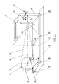
- Figure 1 is shown in diametral section a spherical tank 1, with an external diameter of 650 mm and consisting of a metal liner 2, for example titanium, with a thickness of approximately 1 mm, on which a filamentary envelope 3, for example in "Kevlar".
- a metal liner 2 for example titanium
- a filamentary envelope 3 for example in "Kevlar
- two tubular pins 4 and 5 integral with the liner 2, used to support and rotate the liner for its winding.
- One of the pins will be later closed, however the other will receive a connection for filling and emptying the tank.
- Buckling likely to appear on liner 2 can be found essentially in two areas symmetrical identified in 6 and 7 in Figure 1 and which correspond to the total area of the sphere minus the two poles of the poles corresponding to areas of reinforcement of the thickness of the liner in line with the pins and a small equatorial belt 8.
- the latter corresponds to a connection and welding area of the two hemispheres defining liner 2, an area which therefore presents a better rigidity and is not subject to buckling.
- the method of detecting possible buckling of the liner 2 consists, according to the invention, in making two images interfere holographics of the same area to be checked of sphere 1, taken in two different stress states of the sphere, the applied stress being a constraint thermal exerted, according to an embodiment of the invention, by means of a fluid introduced to inside the sphere and having a different temperature, higher or lower, at room temperature.
- enclosures such as tanks, of revolution, spherical or cylindro-spherical shape example, for which it is necessary to explore practically the entire external surface of the enclosure to control, i.e. to present the latter under the recording laser beam in different positions in order to cover, step by step, the entire said surface, but it is obvious that if the area to be controlled can be fully illuminated by the laser beam in one single pass, it will not be necessary to move the object to control, or even possibly provide means for support and presentation of this object, controlled movement.
- the invention will be described using as fluid applying thermal stress to the air brought to a determined temperature higher than the temperature ambient but we could possibly use it as another gas, or a liquid, such as water, example.
- the fluid applying thermal stress can also just as well be used at a temperature below room temperature.
- FIG. 2 represents a spherical reservoir 1 of the type of Figure 1, supported by a fork-shaped device 9 whose two ends of the fork support the journals 4,5 of the sphere 1.
- the center of the sphere is located on the vertical axis 10 of the fork.
- Controlled movement control means are provided to rotate the axis 10 of the support device and presentation 9 of the desired angle, in one direction or in the other.
- one of the supports for the pins 4.5 is arranged to allow the rotation of sphere 1 around the axis of the trunnions, in one direction or the other, of the desired degree.
- the sphere 1 is likely to be illuminated by a beam symbolized at 11 from a recording or shooting laser 12.
- the beam from the laser 12 is divided by a separator 13 in one part constituting the object bundle 11 and a part constituting the reference beam 14.
- a holographic camera with a thermoplastic film 15 is placed near the divider 13 so as to see the sphere 1 at substantially the same angle as the object beam 11 whose axis is symbolized at 16 and passes through the center of the sphere 1.
- the camera 15 receives the laser beam reflected by sphere 1 as well as, at a determined angle, the beam of reference 14.
- a viewing camera 17 placed behind the camera holographic collects the image of interferograms.
- Figure 2 shows only the parts of the control installation which must be isolated from everything vibration and which must therefore be mounted on a floating chassis symbolized in 18, itself mounted on shock absorbers symbolized in 19.
- the interferometry technique holographic imposes a great stability of the elements optics and the object under test and the vibrations are particularly harmful to the production of holograms.
- shock absorbers 19 The role of the shock absorbers 19 is to filter the frequencies vibrations greater than 5 Hz coming from the ground. Likewise, the motorization of the movements of the support device and presentation of sphere 1 must take this imperative into account and be made for example with slow damped stops.
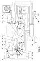
- Figure 3 is a general diagram of an installation of control implementing the method of the invention and incorporating the elements of figure 2, isolated from vibrations from the ground and grouped inside the fictitious frame 20.
- the sphere 1 is shown in Figure 3 in section diametral with the axis of the poles (4,5) in the plane of the figure.
- Holographic interferometry testing requires to apply a constraint to the object under test.
- the constraint is a heat stress applied uniformly to the whole liner and implementation by introducing air at a determined temperature inside the sphere in sight define two different stress states allowing take two holographic shots of the sphere in these two states of constraint.
- Hot air is injected at a temperature and at a rate controlled, from an injection device symbolized in 21, not integral with the assembly 20 and connected by a flexible pipe 22 to a injection pipe 23 to inside the sphere 1 arranged in the pin 4 by example.
- the tip of the cane 23 is arranged as a diffuser and so as to collect the air after circulation at the interior of the sphere, this air being evacuated from the sphere by a second pipe 24 vented to the atmosphere.
- a feedback loop 25 produced by a temperature 26 on the air outlet of the sphere allows to regulate (27) the temperature of the air injected by the device 21.
- the optical circuit includes a recording laser or firing 12 constituted for example by a pulsed laser of the type Ruby whose beam path is materialized by a laser He-Ne 30 plotter.
- the optical assembly is arranged in a cavity folded with a reference arm (14) adaptable in length.
- the holographic recording system consists of by the thermoplastic film camera 15. This type of camera, well known, realizes in situ and in very short times holograms, allowing to proceed in one time relatively short and fully automatic at the realization of successive interferograms.
- a re-reading laser 31 for example of the He-Ne type identical to the laser tracer 30 and whose wavelength is as close as possible to that of the recording laser 12.
- the reading beam 31 is substituted for the reading beam reference 14 using a pivoting mirror 32.
- the viewing camera 17 placed behind the camera thermoplastic film 15 is for example of the video or CCD type and is connected to a control monitor 33.
- the camera 17 collects the image of the interferograms, this image being, parallel to its display on the monitor 33, digitized in an image card placed in the microcomputer 28.
- a printer 34 connected to the microcomputer 28 allows, as will be explained later, to edit a report of sphere control 1.
- Streamer 35 allows backups necessary on the microcomputer 28.
- the microcomputer 28 is of course connected to the means control (link 36) of the rotation of the sphere 1 around of the axis of the poles or journals 4.5 and to the control means (link 37) of the rotation of the support device and presentation 9 (figure 2) of sphere 1.
- an infrared optical pyrometer 38 connected to the microcomputer 28, is responsible for measuring infrared radiation of sphere 1.
- the pyrometer 38 is arranged for example at a distance between 100 and 500 mm from the sphere, in the cone shadow of the latter (compared to the illumination laser).
- Figure 4 shows in a little more detail a particular embodiment of the optical assembly of the installation of figure 2.
- the beam from the recording laser 12 is reflected at 45 ° by a deflection mirror 39 to a divider 13 ', of special design.
- the object beam 11 at the outlet of the separator 13 ' passes through a set 40 of diffuse illumination.
- the reference beam 14 is reflected at 45 ° by a mirror 41, then by reflecting mirrors at angles of 20 ° respectively fixed 42 and adjustable 43, allowing to have optical mounting arms of equilonger (reference beam 14 / object beam 11), and finally by a last mirror 44 of reference to the thermoplastic film camera 15.
- the separator 13 is formed, in accordance with the invention, a movable plate 47 carrying in parallel and side by side a glass slide treated anti-reflection 48 leaving pass the entire beam over the branch reference 14, during the rereading, a separating blade L1 for the control a "Kevlar" surface, a separating blade L2 for the control of a carbon surface and possibly one or several other separating blades adapted to others composite materials.
- a motor (not shown) allows, under the microcomputer 28, to move the wafer 47 to place in the beam returned by the mirror 39 either the separator L1, or the separator L2, depending on the nature of the composite material, i.e. the proofreading blade 48.
- These blades L1, L2 have different characteristics used to adjust the reference 14 / object 11 ratio by depending on the type of composite material.
- the blade 48 makes it possible to keep the same optical path on the reference arm 14 by creating, during the re-reading, the same offset linked to the refraction that the blades L1, L2 during the record.
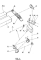
- FIG. 5 schematically illustrates a mode of realization of the support means and presentation of the sphere 1.
- the fork-shaped support 9 comprises for example a vertical shaft 49 mounted swiveling in a system of ball bearings 50 fixed on the floating frame 18 and driven, at its lower end, through of a chain transmission 51, by a stepping motor 52 also mounted on the chassis 18, the latter being connected to the ground, symbolized by a fixed frame 53, by shock absorbers 19.
- the fork 9 also has a lateral extension supporting a stepping motor 54 for driving, for example by a toothed belt 55, a pinion 56 wedged on the axis of pins 4,5 and secured to sphere 1.
- the motor 52 ensures the controlled rotation of the fork 9 around the vertical axis 10, while the motor 54 ensures controlled rotation of sphere 1 around its axis horizontal 4.5.
- the sphere 1 is mounted on the fork 9 as illustrated in example as shown in Figure 1, using ball joints 57 engaged on pins 4, 5 and retained in cages 58 fixed on the fork legs 9.
- One of the pins (4) serves as a passage for the cane diffusing 23.
- the rod 23 which is a simple tube provided with a rounded end pierced with diffusion holes, is arranged inside the duct 24, also introduced into the pin 4, for collecting and removing air from the enclosure.
- the other journal (5) is secured to a hub drive 59, itself secured to said pinion 56 for rotating the sphere 1.
- a second image capture holographic of the same surface part is performed then that the sphere is in a second state of stress thermal due to the presence inside the sphere said flow of air at a determined temperature.
- the second holographic image capture provides a interferogram whose fringe network accounts for disruption of the isodelocation lines and thus signals the presence of a buckling.
- FIGS. 8 and 9 representing, the first, a network regular fringes of an interferogram of an area of the healthy sphere, that is to say one without buckling, and, the second, an interferogram whose network of fringes has singularities indicated by the arrow S, indicative of a buckling.
- the interferogram thus obtained not only makes it possible to report the presence of a buckling (or more than one buckling) separate) but also to locate and circumscribe it precisely inside the surface of the illuminated sphere by the recording laser.
- the first holographic image capture can be performed at room temperature, i.e. before injecting hot air inside the sphere.
- room temperature i.e. before injecting hot air inside the sphere.
- the temperature inside the sphere must be controlled so as to deviate from the ambient temperature without ever exceeding the maximum temperature authorized for the tank safety. This maximum temperature is fixed, for the types of "Kevlar" or carbon tanks indicated higher at 50 ° C.
- Control of the temperature and flow rate of the injected air in sphere 1 allows you to control the ramp up air temperature inside the sphere.
- the second holographic image is taken a few seconds later.
- the the second image is not triggered by function of time because it is difficult to appreciate, from a tank to another, the propagation time of the front thermal through the wall but depending on the elevation of the temperature detected outside of sphere 1 to using the pyrometer 38.
- the trigger threshold of the second image capture for example a rise in temperature detected by the pyrometer 38 by 0.1 or 0.2 ° C compared to the moment the first image is taken.
- the installation allows to repeat automatically and successively the realization of such an interferogram for different parts of the outer surface of the sphere and in a single temperature rise of the sphere between the temperature ambient temperature and the maximum tolerated temperature, for example 50 ° C.
- the operating process is as follows. We first put in places sphere 1 to be checked on the support device and presentation 9 (figure 2). The sphere is positioned from so as to present, as illustrated in FIG. 3, one of its poles or hemispheres (pin 4) towards the laser 12. In fact, so that there is no shadow carried on the holographic image, the beam 11 is positioned so that one of its edges tangent substantially the sphere at said pin 4.
- the heating of the sphere 1 is started by sending by the injection device 21 a flow of hot air at flow rate control.
- the air injected into the sphere 1 is distributed homogeneously, is recovered by the line 24 and, preferably, recycled to the device 21 to limit the heating of the environment, in particular optical equipment.
- Control of the air temperature and its flow, using the devices 21, 27 makes it possible to control the ramp of rise in air temperature inside the sphere.
- Figure 7 is a timing diagram illustrating the rise in temperature of sphere 1 during its control.
- the temperature, detected by the pyrometer 38 will go from the ambient temperature ⁇ a at equilibrium temperature ⁇ e, significantly lower than the maximum limit temperature ⁇ max bearable for composite material. It's during the game straight line of the rise in temperature between ⁇ a and ⁇ e that will be carried out automatically and under the control of the microcomputer 28 the n interferograms corresponding to n parts different from the outer surface of the sphere, necessary and sufficient to cover the entire surface to control.
- the first interferogram I 1 is defined by the two image captures P 1 and P 2 triggered on the basis of the signal supplied by the pyrometer 38.
- the first tap P 1 is triggered from a temperature threshold outside the ambient and the second, upon detection by the pyrometer 38 of a temperature rise ⁇ , from the moment of taking p 1 , equal to 0.1 or 0.2 ° C for example.
- the laser 12 fire orders are given by the microcomputer 28, commanding and controlling by software appropriate all installation parameters as well as the control of the heating means of the sphere, of positioning of the latter, of the holographic camera 15 (advance of the thermoplastic film, heating of the latter for its development).
- the microcomputer 28 also controls for each shot or image capture, tilting the replay mirror 32 (or the displacement of the mirror 46 in the case of the use of the assembly of FIG. 4), switching on the readback laser 31, the acquisition of the image, via the camera 17, for its storage, then return to the initial position of the mirrors 32 or 46.
- Sphere 1 can be fully controlled using six interferograms, namely three with the orientation of the sphere shown in Figure 3, the sphere being simply rotated twice around the axis of pins 4,5 and three other interferograms (and two rotations around the axis 4,5) after rotation (command 37) of 180 ° of the axis 4,5. At during these movements the pyrometer 38 and the devices 21 and 25 remain stationary.
- the video monitor 33 makes it possible to view each interferogram.
- the printer 34 makes it possible to edit a report of the control performed.
- a so-called “manual” function allows the operator, via the microcomputer 28, to access elements of installation or pieces of the program (implementation phase in point, settings, return to an updated singular point during the check).
- the slope of the temperature rise ramp of the sphere (figure 7) can be more or less strong: it depends on the available temperature range between room temperature and the maximum allowable temperature and number interferograms to be performed during the same climb temperature. This is why it is important to plan for air temperature and flow control means injected inside the sphere 1.
- the air must also be clean, dust-free, dehumidified.
- Figure 6 illustrates an embodiment of a box of control grouping together the elements of the installation of the figure 3.
- the various components mechanical and optical of the installation are placed in a fairing or box 61 with hatches or access doors 62 for various manipulations or interventions such as including the placement and removal of the reservoir to control, loading the holographic camera.
- a control and display console is provided and where are grouped the keyboard 63 for dialogue with the microcomputer 28, the latter’s video console 64, the monitor 33 and the printer 34.
- Such a source may be substituted for the source of fluid (21 to 23) described above, without modification of the other parts of the device illustrated in FIG. 3.
Landscapes
- Physics & Mathematics (AREA)
- General Physics & Mathematics (AREA)
- Engineering & Computer Science (AREA)
- Mechanical Engineering (AREA)
- General Engineering & Computer Science (AREA)
- Holo Graphy (AREA)
- Microscoopes, Condenser (AREA)
- Investigating Or Analyzing Materials Using Thermal Means (AREA)
- Investigating Materials By The Use Of Optical Means Adapted For Particular Applications (AREA)
- Investigating Strength Of Materials By Application Of Mechanical Stress (AREA)
- Length Measuring Devices By Optical Means (AREA)
Description
- Figure 1 est une vue schématique en coupe diamétrale d'un réservoir sphérique en matériau composite bobiné sur liner métallique ;
- Figure 2 est un schéma d'une partie d'une installation de contrôle de réservoirs selon l'invention ;
- Figure 3 est un schéma général d'une installation de contrôle de réservoirs mettant en oeuvre le procédé de l'invention ;
- Figure 4 représente de manière plus détaillée le montage optique des dispositifs lasers suivant un mode de mise en oeuvre particulier de l'invention ;
- Figure 5 est un schéma illustrant un mode de mise en oeuvre de moyens de support et de présentation d'une enceinte en vue de son contrôle ;
- Figure 6 est une vue en perspective schématique d'un module ou caisson de contrôle de réservoir mettant en oeuvre le procédé de l'invention ;
- Figure 7 est un chronogramme illustrant la prise successive d'interférogrammes conformément à l'invention ;
- Figure 8 représente un interférogramme d'une zone saine sans flambage, et
- Figure 9 représente un interférogramme d'une zone à défaut.
Claims (21)
- Procédé de contrôle non destructif par interférométrie holographique d'un objet (1) en vue de la détection d'éventuels défauts tels que des flambages, dans lequel on fait interférer deux images holographiques de la même zone à contrôler, prises dans deux états de sollicitation thermique différents, caractérisé en ce que l'objet est une enceinte (1) en matériau composite (3) bobiné sur liner métallique (2), en ce que la sollicitation thermique est appliquée de manière homogène à l'ensemble de la face intérieure de l'enceinte et la prise d'interférogramme est effectuée sur au moins une partie de la face externe de l'enceinte, en ce que la seconde image est prise après avoir porté le liner (2) à une température différente de celle qu'il avait au moment de la prise de la première image et en ce que le déclenchement de la seconde prise d'image est commandé à la détection, à l'extérieur et à proximité de l'enceinte (1), d'une variation, consécutive à la modification de température subie par le liner (2) , du rayonnement infra-rouge externe émis par l'enceinte, égale à un seuil prédéterminé révélant l'arrivée à l'extérieur de l'enceinte du front thermique engendré par la modification de température à l'intérieur, en sorte de faire apparaítre sur ledit interférogramme un réseau de franges rendant compte d'éventuelles perturbations de lignes d'isodéplacement locales de la surface externe consécutives à un défaut.
- Procédé suivant la revendication 1, caractérisé en ce que ledit liner (2) est porté à ladite température différente par application à l'intérieur de l'enceinte (1) d'un fluide.
- Procédé suivant la revendication 1, caractérisé en ce que ledit liner (2) est porté à ladite température différente par introduction à l'intérieur de l'enceinte (1) d'une source de rayonnement infra-rouge.
- Procédé suivant les revendications 1 et 2, caractérisé en ce que l'application dudit fluide à l'intérieur de l'enceinte (1) est faite avant le déclenchement de la première prise d'image.
- Procédé suivant les revendications 2 et 4, caractérisé en ce que le déclenchement de la première prise d'image est effectué après que la température de l'enceinte (1) a atteint, à partir de la température ambiante, la partie rectiligne de la rampe, de montée ou de descente de la température de l'enceinte consécutive à l'application dudit fluide à l'intérieur de ladite enceinte.
- Procédé suivant la revendication 5, caractérisé en ce que le fluide appliqué à l'intérieur de l'enceinte (1) est régulé en température et en débit en sorte d'amener la température de l'enceinte (1) entre la température ambiante et une température limite prédéterminée suivant une courbe de montée, ou descente, rectiligne.
- Procédé suivant l'une des revendications 1 à 3, caractérisé en ce qu'après avoir effectué sur une partie déterminée de la surface de l'enceinte (1) un premier interférogramme par la prise desdites première et seconde images, on effectue sur une deuxième partie de ladite surface, un deuxième interférogramme dans des conditions analogues et on renouvelle l'opération autant de fois que nécessaire pour couvrir toute la zone à contrôler de l'enceinte, en sorte d'obtenir au total n interférogrammes.
- Procédé suivant la revendication 6 ou 7, caractérisé en ce que les interférogrammes sont réalisés les uns à la suite des autres, au cours de la même variation de la température de l'enceinte (1).
- Procédé suivant l'une des revendications 6 à 8, caractérisé en ce que pour chaque interférogramme la prise de la seconde image est déclenchée à la détection, à l'extérieur et à proximité de l'enceinte, d'une variation de la température de l'enceinte par rapport à la température à l'instant de la prise de la première image, égale à un seuil prédéterminé.
- Procédé suivant la revendication 9, caractérisé en ce que ledit seuil de variation de température est de l'ordre de 0,1 à 0,2 °C.
- Procédé suivant l'une des revendications 2, 4 à 10, caractérisé en ce que le fluide appliqué à l'intérieur de l'enceinte (1) est de l'air.
- Dispositif pour la mise en oeuvre du procédé selon l'une des revendications 1 à 3, comportant des moyens (9) de support de l'objet (1) à contrôler, une caméra holographique (15), un montage optique comprenant un laser d'enregistrement (12) et des moyens optiques (13,32 ; 40 à 46) pour l'obtention de faisceaux objet (11), de référence (14), et de relecture, caractérisé en ce que les moyens (9) de support de l'objet à contrôler sont agencés de manière à supporter l'enceinte (1), en ce qu'il comprend, en outre, un laser de relecture (31), des moyens (21 à 23) pour appliquer de manière homogène à l'ensemble de la face interne de l'enceinte (1) une sollicitation thermique, des moyens (38) pour détecter un seuil prédéterminé de variation de la température d'au moins une partie de la face externe de l'enceinte (1), par le rayonnement infra-rouge externe émis par l'enceinte et des moyens (28) reliés à la caméra holographique (15), aux lasers d'enregistrement (12) et de relecture (31) et auxdits moyens (38) de détection de la température de l'enceinte (1) pour commander les prises d'images holographiques.
- Dispositif suivant la revendication 12, caractérisé en ce que lesdits moyens de support de l'enceinte (1) à contrôler sont constitués par un support en forme de fourche (9) aux extrémités de laquelle est fixée de manière amovible l'enceinte (1) suivant un axe de symétrie de cette dernière, des moyens (9a à 9g) étant prévus pour faire pivoter de manière contrôlée, d'une part, l'enceinte autour dudit axe et, d'autre part, ledit support en forme de fourche (9) autour d'un axe perpendiculaire audit axe de l'enceinte (1).
- Dispositif suivant la revendication 12 ou 13, caractérisé en ce que lesdits moyens pour faire varier la température du liner (2) de l'enceinte (1) sont des moyens pour injecter à l'intérieur de l'enceinte un fluide, des moyens (25, 29) étant prévus pour contrôler la température et le débit dudit fluide.
- Dispositif suivant la revendication 14, caractérisé en ce que lesdits moyens pour injecter le fluide à l'intérieur de l'enceinte (1) sont une canne diffusante (23) associée à une canalisation (24) d'évacuation du fluide après circulation à l'intérieur de l'enceinte.
- Dispositif suivant la revendication 15, caractérisé en ce que ladite canalisation (24) d'évacuation du fluide est reliée à un circuit de recyclage du fluide à l'intérieur de l'enceinte (1).
- Dispositif suivant la revendication 12 ou 13, caractérisé en ce que lesdits moyens pour faire varier la température du liner (2) de l'enceinte (1) sont une source de rayonnement infra-rouge.
- Dispositif suivant l'une des revendications 12 à 17, caractérisé en ce que les moyens de support (9) et de positionnement (49 à 56) de l'enceinte (1) à contrôler et les moyens optiques d'enregistrement holographiques sont montés sur un châssis flottant (18) reliés au sol par un système amortisseur (19).
- Dispositif suivant l'une des revendications 12 à 18, caractérisé en ce qu'il comporte, en outre, une caméra de visualisation (17) placée derrière la caméra holographique (15) et reliée à un moniteur vidéo (33).
- Dispositif suivant l'une des revendications 12 à 19, caractérisé en ce que le montage optique comporte une séparatrice constituée d'une plaquette (47) mobile de façon à présenter dans l'axe du faisceau des lasers d'enregistrement (12) et de relecture (31), soit l'une de plusieurs lames séparatrices (L1,L2) de caractéristiques adaptées à la nature du matériau composite de l'enceinte, en vue du réglage du rapport faisceau de référence (14)/ faisceau objet (11), soit une lame (48) laissant passer l'intégralité du faisceau laser sur la branche référence (14), lors de la relecture.
- Dispositif suivant l'une des revendications 12 à 20, caractérisé en ce qu'il comporte un micro-ordinateur (28), équipé d'une imprimante (34) et relié aux divers éléments, composants ou paramètres à commander et/ou contrôler, de la caméra holographique (15), des lasers (12,30,31) et du montage optique, des moyens de support et positionnement (9) de l'enceinte (1), des moyens (23) pour faire varier la température du liner (2) de l'enceinte, des moyens (38) de détection de la température de l'enceinte à l'extérieur de celle-ci, et l'éventuelle caméra de visualisation (17), ledit micro-ordinateur (28) étant programmé pour effectuer automatiquement une séquence complète d'interférogrammes de contrôle de l'enceinte (1).
Applications Claiming Priority (2)
| Application Number | Priority Date | Filing Date | Title |
|---|---|---|---|
| FR9101982 | 1991-02-13 | ||
| FR9101982A FR2672684B1 (fr) | 1991-02-13 | 1991-02-13 | Procede et dispositif de controle non destructif par interferometrie holographique d'enceintes en materiau composite bobine sur liner metallique. |
Publications (2)
| Publication Number | Publication Date |
|---|---|
| EP0499559A1 EP0499559A1 (fr) | 1992-08-19 |
| EP0499559B1 true EP0499559B1 (fr) | 1998-06-24 |
Family
ID=9409888
Family Applications (1)
| Application Number | Title | Priority Date | Filing Date |
|---|---|---|---|
| EP92450001A Expired - Lifetime EP0499559B1 (fr) | 1991-02-13 | 1992-02-07 | Procédé et dispositif de contrÔle non-destructif par interféromètre holographique d'enceintes en matériau composite |
Country Status (8)
| Country | Link |
|---|---|
| US (1) | US5448352A (fr) |
| EP (1) | EP0499559B1 (fr) |
| JP (1) | JPH05113419A (fr) |
| AT (1) | ATE167737T1 (fr) |
| CA (1) | CA2061097A1 (fr) |
| DE (1) | DE69225986T2 (fr) |
| ES (1) | ES2119805T3 (fr) |
| FR (1) | FR2672684B1 (fr) |
Cited By (1)
| Publication number | Priority date | Publication date | Assignee | Title |
|---|---|---|---|---|
| CN113390360A (zh) * | 2021-06-16 | 2021-09-14 | 内蒙古工业大学 | 一种槽式太阳能集热管形变检测方法及装置 |
Families Citing this family (8)
| Publication number | Priority date | Publication date | Assignee | Title |
|---|---|---|---|---|
| US5786533A (en) * | 1996-04-17 | 1998-07-28 | Michelin North America, Inc. | Method for analyzing a separation in a deformable structure |
| FR2770639B1 (fr) * | 1997-11-05 | 2000-01-21 | Aerospatiale | Procede de mesure de l'expansion de volume d'un reservoir pressurise et dispositif pour sa mise en oeuvre |
| US20070277919A1 (en) | 2006-05-16 | 2007-12-06 | The Boeing Company | Systems and methods for monitoring automated composite manufacturing processes |
| DE102007040353B3 (de) * | 2007-08-27 | 2009-04-23 | Mähner, Bernward | Vorrichtung zum Prüfen eines Prüfobjekts, insbesondere eines Reifens, mittels eines zerstörungsfreien Messverfahrens |
| RU2580411C1 (ru) * | 2015-01-12 | 2016-04-10 | Федеральное государственное автономное образовательное учреждение высшего образования "Национальный исследовательский Томский политехнический университет" | Тепловизионный дефектоскоп |
| WO2019028465A1 (fr) * | 2017-08-04 | 2019-02-07 | University Of South Florida | Système et procédé sans contact pour détecter des défauts dans le cadre d'un processus de fabrication additive |
| EP3757445A1 (fr) * | 2019-06-24 | 2020-12-30 | Hexagon Ragasco AS | Système et procédé de test de récipients sous pression composites |
| CN116678340B (zh) * | 2023-07-28 | 2023-12-12 | 华能澜沧江水电股份有限公司 | 引张线测量装置及其控制方法 |
Family Cites Families (12)
| Publication number | Priority date | Publication date | Assignee | Title |
|---|---|---|---|---|
| US3644047A (en) * | 1969-05-08 | 1972-02-22 | Gc Optronics Inc | Apparatus and method of simultaneously inspecting a plurality of surfaces of a body by holographic interferometry |
| FR2048189A5 (en) * | 1969-06-03 | 1971-03-19 | Cooptronics Inc | Holographic detection of the deformation - of objects |
| US3711202A (en) * | 1969-12-08 | 1973-01-16 | Rohr Corp | Holographic testing apparatus |
| US3681970A (en) * | 1970-03-09 | 1972-08-08 | G C Optronics Inc | Method of flaw detection using internal heating |
| US3797938A (en) * | 1972-10-16 | 1974-03-19 | Trw Inc | Optical apparatus for measuring deformation of parabolic antennas |
| DE2312435C3 (de) * | 1973-03-13 | 1978-06-08 | Opto-Produkte Ag, Zuerich (Schweiz) | Holographische Anordnung zur Ermittlung unregelmäßiger Verformungen durch zerstörungsfreie Werkstoffprüfung |
| US3938889A (en) * | 1974-06-04 | 1976-02-17 | The United States Of America As Represented By The Secretary Of The Air Force | Method and apparatus for measuring linear thermal expansion of polymeric material |
| US4234256A (en) * | 1978-04-03 | 1980-11-18 | The Goodyear Tire & Rubber Company | Determining depth location of separations within a tire |
| GB2021802A (en) * | 1978-05-20 | 1979-12-05 | Rolls Royce | Measuring wall thickness holographically |
| US4506981A (en) * | 1982-10-14 | 1985-03-26 | The B. F. Goodrich Company | Method for detection of blown beads in pneumatic tires |
| FR2568026B1 (fr) * | 1984-07-19 | 1988-09-16 | Aerospatiale | Camera holographique et dispositif de controle non-destructif utilisant une telle camera |
| US4999681A (en) * | 1988-06-24 | 1991-03-12 | Mader David L | Real-time halographic interferometry with a pulsed laser and flicker-free viewing |
-
1991
- 1991-02-13 FR FR9101982A patent/FR2672684B1/fr not_active Expired - Fee Related
-
1992
- 1992-02-07 EP EP92450001A patent/EP0499559B1/fr not_active Expired - Lifetime
- 1992-02-07 AT AT92450001T patent/ATE167737T1/de not_active IP Right Cessation
- 1992-02-07 DE DE69225986T patent/DE69225986T2/de not_active Expired - Fee Related
- 1992-02-07 ES ES92450001T patent/ES2119805T3/es not_active Expired - Lifetime
- 1992-02-12 CA CA002061097A patent/CA2061097A1/fr not_active Abandoned
- 1992-02-13 JP JP4059291A patent/JPH05113419A/ja active Pending
-
1994
- 1994-12-20 US US08/359,859 patent/US5448352A/en not_active Expired - Fee Related
Cited By (1)
| Publication number | Priority date | Publication date | Assignee | Title |
|---|---|---|---|---|
| CN113390360A (zh) * | 2021-06-16 | 2021-09-14 | 内蒙古工业大学 | 一种槽式太阳能集热管形变检测方法及装置 |
Also Published As
| Publication number | Publication date |
|---|---|
| JPH05113419A (ja) | 1993-05-07 |
| US5448352A (en) | 1995-09-05 |
| EP0499559A1 (fr) | 1992-08-19 |
| FR2672684A1 (fr) | 1992-08-14 |
| ES2119805T3 (es) | 1998-10-16 |
| ATE167737T1 (de) | 1998-07-15 |
| FR2672684B1 (fr) | 1994-02-04 |
| DE69225986T2 (de) | 1999-03-25 |
| DE69225986D1 (de) | 1998-07-30 |
| CA2061097A1 (fr) | 1992-08-14 |
Similar Documents
| Publication | Publication Date | Title |
|---|---|---|
| EP0499559B1 (fr) | Procédé et dispositif de contrÔle non-destructif par interféromètre holographique d'enceintes en matériau composite | |
| JPH0521420B2 (fr) | ||
| WO2013139718A1 (fr) | Procédé et dispositif de contrôle d'un matériau composite par ultrasons laser | |
| EP0310526B1 (fr) | Procédé et dispositif de contrôle de la pression régnant dans une enceinte ou capacité | |
| EP0234982B1 (fr) | Dispositif de contrôle non-destructif d'une pièce par holographie optique | |
| EP0965038B1 (fr) | Procede d'examen photothermique d'une piece | |
| CA2054973A1 (fr) | Dispositif de test d'equipements en mouvement | |
| FR2897158A1 (fr) | Dispositif et procede manuel de positionnement d'une source de radiographie par rayons gamma d'au moins une soudure d'une tubulure. | |
| FR2499718A1 (fr) | Procede et dispositif pour la detection des defauts de surface des pieces mecaniques, en particulier des pieces a surface courbe | |
| EP1099947A2 (fr) | Procédé et dispositif pour faire un essai optique d'un pneu | |
| EP4731978A1 (fr) | Système de mesure de pression différentielle en milieu sous-marin | |
| FR2568026A1 (fr) | Camera holographique et dispositif de controle non-destructif utilisant une telle camera | |
| US20080291458A1 (en) | Holographic interferometry for non-destructive testing of power sources | |
| EP0668493A1 (fr) | Procédé et dispositif de contrôle de nids d'abeilles à l'aide de fibres optiques | |
| EP3781902B1 (fr) | Dispositif de mesure pour déterminer l'épaisseur d'une couche d'un matériau | |
| FR2634026A1 (fr) | ||
| FR2580396A1 (fr) | Dispositif pour indiquer et/ou mesurer les ecoulements de matiere extremement faibles | |
| FR2908674A1 (fr) | Dispositif de nettoyage et de depollution d'un objet a environnement confine non etanche limite par une paroi a membrane souple | |
| FR2570502A1 (fr) | Installation pour le controle ultrasonore de pieces, et dispositif pour balayer une surface de la piece a controler | |
| EP0056554B1 (fr) | Dispositif de contrôle en service de l'intégrité des soudures des structures off-shore | |
| EP3182097B1 (fr) | Dispositif de contrôle par tomographie en cohérence optique notamment dans un congé d'une pièce composite | |
| EP0329554B1 (fr) | Procédé et installation de détection de crayons non étanches dans un assemblage de combustible nucléaire | |
| FR2515347A1 (fr) | Procede de detection et de localisation de micro-fuites dans une paroi et notamment dans la barriere secondaire des cuves de methaniers | |
| FR2591341A1 (fr) | Technique de detection de defauts optiques sur ligne de production de verre | |
| FR2908875A1 (fr) | Dispositif de mesure sans contact de la deformation d'une membrane, et applications |
Legal Events
| Date | Code | Title | Description |
|---|---|---|---|
| PUAI | Public reference made under article 153(3) epc to a published international application that has entered the european phase |
Free format text: ORIGINAL CODE: 0009012 |
|
| AK | Designated contracting states |
Kind code of ref document: A1 Designated state(s): AT BE CH DE ES FR GB IT LI LU NL |
|
| 17P | Request for examination filed |
Effective date: 19930129 |
|
| 17Q | First examination report despatched |
Effective date: 19930701 |
|
| APCB | Communication from the board of appeal sent |
Free format text: ORIGINAL CODE: EPIDOS OBAPE |
|
| APCB | Communication from the board of appeal sent |
Free format text: ORIGINAL CODE: EPIDOS OBAPE |
|
| APCB | Communication from the board of appeal sent |
Free format text: ORIGINAL CODE: EPIDOS OBAPE |
|
| APCB | Communication from the board of appeal sent |
Free format text: ORIGINAL CODE: EPIDOS OBAPE |
|
| APCB | Communication from the board of appeal sent |
Free format text: ORIGINAL CODE: EPIDOS OBAPE |
|
| APCB | Communication from the board of appeal sent |
Free format text: ORIGINAL CODE: EPIDOS OBAPE |
|
| APAB | Appeal dossier modified |
Free format text: ORIGINAL CODE: EPIDOS NOAPE |
|
| GRAG | Despatch of communication of intention to grant |
Free format text: ORIGINAL CODE: EPIDOS AGRA |
|
| GRAG | Despatch of communication of intention to grant |
Free format text: ORIGINAL CODE: EPIDOS AGRA |
|
| GRAH | Despatch of communication of intention to grant a patent |
Free format text: ORIGINAL CODE: EPIDOS IGRA |
|
| GRAH | Despatch of communication of intention to grant a patent |
Free format text: ORIGINAL CODE: EPIDOS IGRA |
|
| GRAA | (expected) grant |
Free format text: ORIGINAL CODE: 0009210 |
|
| AK | Designated contracting states |
Kind code of ref document: B1 Designated state(s): AT BE CH DE ES FR GB IT LI LU NL |
|
| PG25 | Lapsed in a contracting state [announced via postgrant information from national office to epo] |
Ref country code: NL Free format text: LAPSE BECAUSE OF FAILURE TO SUBMIT A TRANSLATION OF THE DESCRIPTION OR TO PAY THE FEE WITHIN THE PRESCRIBED TIME-LIMIT Effective date: 19980624 Ref country code: AT Free format text: LAPSE BECAUSE OF FAILURE TO SUBMIT A TRANSLATION OF THE DESCRIPTION OR TO PAY THE FEE WITHIN THE PRESCRIBED TIME-LIMIT Effective date: 19980624 |
|
| REF | Corresponds to: |
Ref document number: 167737 Country of ref document: AT Date of ref document: 19980715 Kind code of ref document: T |
|
| REG | Reference to a national code |
Ref country code: CH Ref legal event code: EP |
|
| REF | Corresponds to: |
Ref document number: 69225986 Country of ref document: DE Date of ref document: 19980730 |
|
| GBT | Gb: translation of ep patent filed (gb section 77(6)(a)/1977) |
Effective date: 19980911 |
|
| REG | Reference to a national code |
Ref country code: ES Ref legal event code: FG2A Ref document number: 2119805 Country of ref document: ES Kind code of ref document: T3 |
|
| NLV1 | Nl: lapsed or annulled due to failure to fulfill the requirements of art. 29p and 29m of the patents act | ||
| PGFP | Annual fee paid to national office [announced via postgrant information from national office to epo] |
Ref country code: GB Payment date: 19990125 Year of fee payment: 8 |
|
| PG25 | Lapsed in a contracting state [announced via postgrant information from national office to epo] |
Ref country code: LU Free format text: LAPSE BECAUSE OF NON-PAYMENT OF DUE FEES Effective date: 19990207 |
|
| PGFP | Annual fee paid to national office [announced via postgrant information from national office to epo] |
Ref country code: ES Payment date: 19990222 Year of fee payment: 8 |
|
| PG25 | Lapsed in a contracting state [announced via postgrant information from national office to epo] |
Ref country code: LI Free format text: LAPSE BECAUSE OF NON-PAYMENT OF DUE FEES Effective date: 19990228 Ref country code: CH Free format text: LAPSE BECAUSE OF NON-PAYMENT OF DUE FEES Effective date: 19990228 |
|
| PGFP | Annual fee paid to national office [announced via postgrant information from national office to epo] |
Ref country code: BE Payment date: 19990316 Year of fee payment: 8 |
|
| PGFP | Annual fee paid to national office [announced via postgrant information from national office to epo] |
Ref country code: DE Payment date: 19990406 Year of fee payment: 8 |
|
| PLBE | No opposition filed within time limit |
Free format text: ORIGINAL CODE: 0009261 |
|
| 26N | No opposition filed | ||
| REG | Reference to a national code |
Ref country code: CH Ref legal event code: PL |
|
| PG25 | Lapsed in a contracting state [announced via postgrant information from national office to epo] |
Ref country code: GB Free format text: LAPSE BECAUSE OF NON-PAYMENT OF DUE FEES Effective date: 20000207 |
|
| PG25 | Lapsed in a contracting state [announced via postgrant information from national office to epo] |
Ref country code: ES Free format text: LAPSE BECAUSE OF NON-PAYMENT OF DUE FEES Effective date: 20000208 |
|
| PG25 | Lapsed in a contracting state [announced via postgrant information from national office to epo] |
Ref country code: BE Free format text: LAPSE BECAUSE OF NON-PAYMENT OF DUE FEES Effective date: 20000228 |
|
| PGFP | Annual fee paid to national office [announced via postgrant information from national office to epo] |
Ref country code: FR Payment date: 20000228 Year of fee payment: 9 |
|
| BERE | Be: lapsed |
Owner name: AEROSPATIALE SOC. NATIONALE INDUSTRIELLE Effective date: 20000228 |
|
| GBPC | Gb: european patent ceased through non-payment of renewal fee |
Effective date: 20000207 |
|
| PG25 | Lapsed in a contracting state [announced via postgrant information from national office to epo] |
Ref country code: DE Free format text: LAPSE BECAUSE OF NON-PAYMENT OF DUE FEES Effective date: 20001201 |
|
| PG25 | Lapsed in a contracting state [announced via postgrant information from national office to epo] |
Ref country code: FR Free format text: LAPSE BECAUSE OF NON-PAYMENT OF DUE FEES Effective date: 20011031 |
|
| REG | Reference to a national code |
Ref country code: ES Ref legal event code: FD2A Effective date: 20010910 |
|
| REG | Reference to a national code |
Ref country code: FR Ref legal event code: ST |
|
| PG25 | Lapsed in a contracting state [announced via postgrant information from national office to epo] |
Ref country code: IT Free format text: LAPSE BECAUSE OF NON-PAYMENT OF DUE FEES;WARNING: LAPSES OF ITALIAN PATENTS WITH EFFECTIVE DATE BEFORE 2007 MAY HAVE OCCURRED AT ANY TIME BEFORE 2007. THE CORRECT EFFECTIVE DATE MAY BE DIFFERENT FROM THE ONE RECORDED. Effective date: 20050207 |
|
| APAH | Appeal reference modified |
Free format text: ORIGINAL CODE: EPIDOSCREFNO |