EP0499670A1 - Dispositif de commande de valves - Google Patents
Dispositif de commande de valves Download PDFInfo
- Publication number
- EP0499670A1 EP0499670A1 EP91102469A EP91102469A EP0499670A1 EP 0499670 A1 EP0499670 A1 EP 0499670A1 EP 91102469 A EP91102469 A EP 91102469A EP 91102469 A EP91102469 A EP 91102469A EP 0499670 A1 EP0499670 A1 EP 0499670A1
- Authority
- EP
- European Patent Office
- Prior art keywords
- valve
- control device
- frame
- valve control
- housing
- Prior art date
- Legal status (The legal status is an assumption and is not a legal conclusion. Google has not performed a legal analysis and makes no representation as to the accuracy of the status listed.)
- Granted
Links
- 238000005266 casting Methods 0.000 claims abstract description 4
- 239000012530 fluid Substances 0.000 claims abstract description 3
- MEKOFIRRDATTAG-UHFFFAOYSA-N 2,2,5,8-tetramethyl-3,4-dihydrochromen-6-ol Chemical compound C1CC(C)(C)OC2=C1C(C)=C(O)C=C2C MEKOFIRRDATTAG-UHFFFAOYSA-N 0.000 claims abstract 3
- 229910000679 solder Inorganic materials 0.000 claims description 10
- 150000001875 compounds Chemical class 0.000 description 5
- 238000007789 sealing Methods 0.000 description 3
- 230000008878 coupling Effects 0.000 description 2
- 238000010168 coupling process Methods 0.000 description 2
- 238000005859 coupling reaction Methods 0.000 description 2
- 238000004519 manufacturing process Methods 0.000 description 2
- 229920003023 plastic Polymers 0.000 description 2
- 239000004033 plastic Substances 0.000 description 2
- 238000004382 potting Methods 0.000 description 2
- 229910052782 aluminium Inorganic materials 0.000 description 1
- XAGFODPZIPBFFR-UHFFFAOYSA-N aluminium Chemical compound [Al] XAGFODPZIPBFFR-UHFFFAOYSA-N 0.000 description 1
- 239000011324 bead Substances 0.000 description 1
- 239000004020 conductor Substances 0.000 description 1
- 238000011161 development Methods 0.000 description 1
- 230000018109 developmental process Effects 0.000 description 1
- 230000007613 environmental effect Effects 0.000 description 1
- 230000017525 heat dissipation Effects 0.000 description 1
- 239000012528 membrane Substances 0.000 description 1
- 229910052751 metal Inorganic materials 0.000 description 1
- 239000002184 metal Substances 0.000 description 1
- 229920002635 polyurethane Polymers 0.000 description 1
- 239000004814 polyurethane Substances 0.000 description 1
- 238000005476 soldering Methods 0.000 description 1
- 238000004804 winding Methods 0.000 description 1
Images

Classifications
-
- H—ELECTRICITY
- H05—ELECTRIC TECHNIQUES NOT OTHERWISE PROVIDED FOR
- H05K—PRINTED CIRCUITS; CASINGS OR CONSTRUCTIONAL DETAILS OF ELECTRIC APPARATUS; MANUFACTURE OF ASSEMBLAGES OF ELECTRICAL COMPONENTS
- H05K7/00—Constructional details common to different types of electric apparatus
- H05K7/14—Mounting supporting structure in casing or on frame or rack
-
- B—PERFORMING OPERATIONS; TRANSPORTING
- B60—VEHICLES IN GENERAL
- B60T—VEHICLE BRAKE CONTROL SYSTEMS OR PARTS THEREOF; BRAKE CONTROL SYSTEMS OR PARTS THEREOF, IN GENERAL; ARRANGEMENT OF BRAKING ELEMENTS ON VEHICLES IN GENERAL; PORTABLE DEVICES FOR PREVENTING UNWANTED MOVEMENT OF VEHICLES; VEHICLE MODIFICATIONS TO FACILITATE COOLING OF BRAKES
- B60T13/00—Transmitting braking action from initiating means to ultimate brake actuator with power assistance or drive; Brake systems incorporating such transmitting means, e.g. air-pressure brake systems
- B60T13/10—Transmitting braking action from initiating means to ultimate brake actuator with power assistance or drive; Brake systems incorporating such transmitting means, e.g. air-pressure brake systems with fluid assistance, drive, or release
- B60T13/66—Electrical control in fluid-pressure brake systems
- B60T13/68—Electrical control in fluid-pressure brake systems by electrically-controlled valves
-
- B—PERFORMING OPERATIONS; TRANSPORTING
- B60—VEHICLES IN GENERAL
- B60T—VEHICLE BRAKE CONTROL SYSTEMS OR PARTS THEREOF; BRAKE CONTROL SYSTEMS OR PARTS THEREOF, IN GENERAL; ARRANGEMENT OF BRAKING ELEMENTS ON VEHICLES IN GENERAL; PORTABLE DEVICES FOR PREVENTING UNWANTED MOVEMENT OF VEHICLES; VEHICLE MODIFICATIONS TO FACILITATE COOLING OF BRAKES
- B60T8/00—Arrangements for adjusting wheel-braking force to meet varying vehicular or ground-surface conditions, e.g. limiting or varying distribution of braking force
- B60T8/32—Arrangements for adjusting wheel-braking force to meet varying vehicular or ground-surface conditions, e.g. limiting or varying distribution of braking force responsive to a speed condition, e.g. acceleration or deceleration
- B60T8/34—Arrangements for adjusting wheel-braking force to meet varying vehicular or ground-surface conditions, e.g. limiting or varying distribution of braking force responsive to a speed condition, e.g. acceleration or deceleration having a fluid pressure regulator responsive to a speed condition
- B60T8/36—Arrangements for adjusting wheel-braking force to meet varying vehicular or ground-surface conditions, e.g. limiting or varying distribution of braking force responsive to a speed condition, e.g. acceleration or deceleration having a fluid pressure regulator responsive to a speed condition including a pilot valve responding to an electromagnetic force
- B60T8/3615—Electromagnetic valves specially adapted for anti-lock brake and traction control systems
- B60T8/3675—Electromagnetic valves specially adapted for anti-lock brake and traction control systems integrated in modulator units
Definitions
- valve control device e.g. an electronic control unit for an anti-lock braking system (ABS), in which the brake fluid actuating the wheel brakes is controlled with two valves per wheel.
- ABS anti-lock braking system
- the valves are each operated by an electromagnet and are usually combined in a so-called valve block.
- the invention has for its object to provide a valve control device which is able to compensate for manufacturing tolerances of the valve block and thus enables easy assembly.
- valve control device having the features of claim 1.
- the resilient embedding of the electromagnetic coils in the housing frame has the advantage that the elastic mass in which the coils are embedded simultaneously seals the electronic components of the valve control unit from the environment.
- a valve control device 1 (FIG. 1) has a housing which essentially consists of a housing frame 2 and a cover 3.
- the frame 2 is e.g. made of aluminum and the lid 3 made of plastic.
- Valve coils 4 ie the coil bodies and windings of the individual electromagnets for valve actuation, are resiliently embedded in the frame 2. This is achieved, for example, in that the valve coils 4 are fixed in their position relative to the frame 2 and the spaces are filled with a sealing compound 6.
- a suitable plastic for example a polyurethane with the necessary elasticity, is used as the potting compound. After the casting compound 6 has hardened, the valve coils 4 are held in their position, but the holder is so flexible that manufacturing tolerances of the valve block (compare FIGS. 4 and 5) are easily compensated for.
- the sealing compound 6 seals the electrical components still to be described against the Valve block and against the environment, so that they are protected against environmental influences.
- a circuit carrier which receives the electrical and electronic circuit components, which in the exemplary embodiment shown consists of a first printed circuit board 7 and a second printed circuit board 8 which are flexibly connected to one another by two ribbon cables 9, 10.
- the circuit boards 7 and 8 are only shown schematically, since the circuit itself is not part of the invention. Suitable ABS control circuits are known in multiple versions.
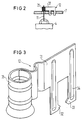
- the connecting wires 11 of the valve coils 4 are connected to the power modules arranged on the circuit board 2 via solder contacts 12, which in turn are connected to conductor tracks of the circuit board 7 (not shown) and which will be explained in detail with reference to FIGS. 3 and 4.
- the ribbon cables 9 and 10 are connected to the printed circuit board 7 by being inserted into holders 13 and 14, respectively. They are connected to the printed circuit board 8 via corresponding holders 15 and 16.
- the colders 13 to 16 are fastened on the respective printed circuit boards 7, 8 by latching hooks 16a which are inserted through bores in the respective printed circuit board.
- Power components 17, of which only one is shown in the drawing, are glued to the housing frame 2 over a wide area for better heat dissipation. Your upturned connecting legs are inserted through contact holes in the circuit board 7 and soldered. In order to be able to securely insert the connecting legs into the contact holes during assembly, a foldable threading aid 18 is fastened to the frame 2.
- a plug part in the form of a male connector 19 is fastened to the cover 3 with rivets 20. It is electrically connected to the printed circuit board 8 by lines 21. Not one in the drawing The illustrated connector coupling part is pushed onto the male connector with two screws 22 attached to the cover 3.
- a seal 26 ensures tightness.
- the housing frame 2 is provided on its upper edge with a continuous groove into which a seal 27 is inserted, which ensures tightness between the frame 2 and the cover 3.
- the cover 3 is screwed to the frame 2 by four screws 29.
- the entire valve housing 1 is fastened to the valve block with two screws 30.
- the solder contacts 12 are formed as a sheet metal part. They have a fastening lug 31 which is provided with two latching hooks 32, 33 which protrude downward and which are each reinforced by a bead 34. A cylindrical shaped pad 35 connects to the fastening tab 31.
- the fastening tab 31 can be coated with a solder resist.
- the latching hooks 32, 33 are inserted through corresponding bores in the printed circuit board 7 and then snap into place on the underside thereof.
- the circuit board 7 is then inserted into the frame 2 so that the connecting wires 11 of the valve coils 4 each protrude through a solder eye 35.
- the circuit board 7 is placed together with the frame 2 in a solder bath - for example a wave solder bath - in which the connecting wires 11 are soldered to the respective solder contact 12.
- the latching hooks 32, 33 are also soldered to the printed circuit board 7.
- the surge side during soldering is the side of the printed circuit board 7 which is at the top in the drawing.
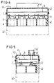
- valve control device 41 (FIGS. 4 and 5) is shown in the assembled state, an associated valve block 40 being indicated by dashed lines. It has eight individual valve housings or valve domes 44, which are already inserted into the coil bodies of the solenoid valve coils 4 here.
- the potting compound 6, which fixes the valve coils 4 in the frame 42, enables the valve control device 41 to be simply pushed onto the valve block 40 due to its flexibility.
- the valve control unit 41 largely corresponds to the valve control unit 1.
- the cover 43 which can be made in one or two parts, has here, however, a plug part 45 projecting vertically upwards, which is also provided with a knife strip 46.
- the circuit board 7 also forms the power board here, it is provided with power modules 17, while the circuit board 8 forms the processor board. Both printed circuit boards 7 and 8 connected by ribbon cable 9 can also be replaced by an elastic printed circuit board.
Landscapes
- Engineering & Computer Science (AREA)
- Physics & Mathematics (AREA)
- Electromagnetism (AREA)
- Transportation (AREA)
- Mechanical Engineering (AREA)
- Fluid Mechanics (AREA)
- Microelectronics & Electronic Packaging (AREA)
- Magnetically Actuated Valves (AREA)
Priority Applications (2)
| Application Number | Priority Date | Filing Date | Title |
|---|---|---|---|
| DE59106681T DE59106681D1 (de) | 1991-02-20 | 1991-02-20 | Ventilsteuergerät. |
| EP19910102469 EP0499670B1 (fr) | 1991-02-20 | 1991-02-20 | Dispositif de commande de valves |
Applications Claiming Priority (1)
| Application Number | Priority Date | Filing Date | Title |
|---|---|---|---|
| EP19910102469 EP0499670B1 (fr) | 1991-02-20 | 1991-02-20 | Dispositif de commande de valves |
Publications (2)
| Publication Number | Publication Date |
|---|---|
| EP0499670A1 true EP0499670A1 (fr) | 1992-08-26 |
| EP0499670B1 EP0499670B1 (fr) | 1995-10-11 |
Family
ID=8206433
Family Applications (1)
| Application Number | Title | Priority Date | Filing Date |
|---|---|---|---|
| EP19910102469 Expired - Lifetime EP0499670B1 (fr) | 1991-02-20 | 1991-02-20 | Dispositif de commande de valves |
Country Status (2)
| Country | Link |
|---|---|
| EP (1) | EP0499670B1 (fr) |
| DE (1) | DE59106681D1 (fr) |
Cited By (21)
| Publication number | Priority date | Publication date | Assignee | Title |
|---|---|---|---|---|
| DE4232205A1 (de) * | 1992-09-25 | 1994-03-31 | Siemens Ag | Ventilsteuergerät und Verfahren zu seiner Herstellung |
| WO1994025320A1 (fr) * | 1993-04-30 | 1994-11-10 | Itt Automotive Europe Gmbh | Regulateur electro-hydraulique de pression |
| DE4315206A1 (de) * | 1993-05-07 | 1994-11-10 | Teves Gmbh Alfred | Elektrohydraulische Druckregelvorrichtung |
| WO1995003960A1 (fr) * | 1993-07-29 | 1995-02-09 | Itt Automotive Europe Gmbh | Dispositif electrohydraulique de regulation de la pression |
| DE4327887A1 (de) * | 1993-08-19 | 1995-02-23 | Teves Gmbh Alfred | Elektrohydraulische Druckregelvorrichtung |
| WO1995007201A1 (fr) * | 1993-09-11 | 1995-03-16 | Itt Automotive Europe Gmbh | Regulateur de pression electro-hydraulique |
| WO1995028303A1 (fr) * | 1994-04-13 | 1995-10-26 | Robert Bosch Gmbh | Dispositif electro-hydraulique regulateur de pression, notamment pour le systeme de freinage a patinage controle d'un vehicule |
| WO1996000670A1 (fr) * | 1994-06-28 | 1996-01-11 | Itt Automotive Europe Gmbh | Dispositif de regulation de la pression |
| EP0705747A1 (fr) * | 1994-10-07 | 1996-04-10 | The Whitaker Corporation | Actionneur hydraulique commandé électronique |
| WO1996013416A1 (fr) * | 1994-10-26 | 1996-05-09 | Itt Automotive Europe Gmbh | Groupe hydraulique |
| WO1996013415A1 (fr) * | 1994-10-28 | 1996-05-09 | Siemens Aktiengesellschaft | Dispositif de commande a soupapes |
| WO1996020856A1 (fr) * | 1995-01-07 | 1996-07-11 | Itt Automotive Europe Gmbh | Groupe hydraulique |
| GB2319897B (en) * | 1996-10-25 | 2001-04-18 | Aisin Seiki | Electromagnetic valve unit |
| DE10026564C1 (de) * | 2000-05-30 | 2001-11-29 | Daimler Chrysler Ag | Ventilsteuergerät |
| DE10026570A1 (de) * | 2000-05-30 | 2002-01-03 | Daimler Chrysler Ag | Ventilsteuergerät |
| DE10050291A1 (de) * | 2000-10-10 | 2002-05-08 | Conti Temic Microelectronic | Ventilsteuergerät |
| DE10050288A1 (de) * | 2000-10-19 | 2002-05-16 | Conti Temic Microelectronic | Ventilsteuergerät |
| EP1120592A3 (fr) * | 2000-01-25 | 2002-11-13 | Framatome Connectors International | Dispositif de commande d'une soupape électromagnétique |
| WO2004005094A1 (fr) * | 2002-07-03 | 2004-01-15 | Continental Teves Ag & Co. Ohg | Groupe hydraulique |
| DE10328221A1 (de) * | 2003-06-24 | 2005-01-27 | Sauer-Danfoss Aps | Elektromagnetischer Ventilantrieb |
| WO2010000505A1 (fr) * | 2008-06-30 | 2010-01-07 | Robert Bosch Gmbh | Agencement de commutation électromécanique modulaire |
Families Citing this family (12)
| Publication number | Priority date | Publication date | Assignee | Title |
|---|---|---|---|---|
| DE69308513T2 (de) * | 1992-12-21 | 1997-06-12 | Sumitomo Electric Industries | Antiblockierbremssystem |
| DE4318420A1 (de) * | 1993-06-03 | 1994-12-08 | Bosch Gmbh Robert | Ventilblockaggregat |
| US5758931A (en) * | 1995-03-30 | 1998-06-02 | Sumitomo Wiring Systems, Ltd. | Electric control unit integrated with a hydraulic unit in an anti-lock brake system |
| DE19781961T1 (de) * | 1996-08-20 | 1999-07-15 | Kelsey Hayes Co | Elektromagnetspulenanordnung und -verbindung |
| DE19640261C2 (de) * | 1996-09-30 | 1998-07-16 | Siemens Ag | Ventilsteuergerät mit dreidimensionaler Leiterplatte in MID-Technik |
| DE19704152C2 (de) | 1997-02-04 | 1998-11-05 | Siemens Ag | Steuergerät für ein Antiblockiersystem |
| EP0872396B1 (fr) | 1997-04-16 | 2003-05-21 | Siemens Aktiengesellschaft | Dispositif de commande de valves |
| DE10085047T1 (de) | 1999-09-10 | 2002-11-07 | Kelsey Hayes Co | Elektrohydraulische Steuereinheit für ein elektronisches Bremssteuerungssystem |
| EP1132274B1 (fr) | 2000-02-26 | 2004-04-07 | WABCO GmbH & CO. OHG | Modulateur de pression de freinage pour système de freinage électronique |
| DE10009116A1 (de) * | 2000-02-26 | 2001-08-30 | Wabco Gmbh & Co Ohg | Ventileinrichtung für die Vorsteuereinheit eines Bremsdruckmodulators |
| DE10009117B4 (de) | 2000-02-26 | 2009-07-30 | Wabco Gmbh | Konstruktion eines Bremsdruckmodulators für Anhänger mit elektronischer Bremsanlage |
| DE102005003293A1 (de) * | 2005-01-24 | 2006-07-27 | Continental Teves Ag & Co. Ohg | Befestigungsvorrichtung für Sensoren oder Aktoren |
Citations (6)
| Publication number | Priority date | Publication date | Assignee | Title |
|---|---|---|---|---|
| DE3012650A1 (de) * | 1980-04-01 | 1981-10-15 | Robert Bosch Gmbh, 7000 Stuttgart | Elektrische schaltungsanordnung mit einer leiterplatte und einem nicht auf der leiterplatte befestigten bauelement |
| EP0105219A2 (fr) * | 1982-10-02 | 1984-04-11 | Robert Bosch Gmbh | Système de commande ou de réglage |
| WO1989010286A1 (fr) * | 1988-04-20 | 1989-11-02 | Alfred Teves Gmbh | Dispositif electrohydraulique de regulation de pression |
| DE3836405A1 (de) * | 1988-10-26 | 1990-05-03 | Teves Gmbh Alfred | Platinenanordnung, insbesondere fuer einen ventilblock einer schlupfgeregelten hydraulischen bremsanlage |
| EP0373551A2 (fr) * | 1988-12-12 | 1990-06-20 | LUCAS INDUSTRIES public limited company | Ensemble de régulation de pression, en particulier pour installations de freinage de véhicule |
| DE3906548A1 (de) * | 1989-03-02 | 1990-09-06 | Bosch Gmbh Robert | Drucksteuerventil |
-
1991
- 1991-02-20 DE DE59106681T patent/DE59106681D1/de not_active Expired - Lifetime
- 1991-02-20 EP EP19910102469 patent/EP0499670B1/fr not_active Expired - Lifetime
Patent Citations (6)
| Publication number | Priority date | Publication date | Assignee | Title |
|---|---|---|---|---|
| DE3012650A1 (de) * | 1980-04-01 | 1981-10-15 | Robert Bosch Gmbh, 7000 Stuttgart | Elektrische schaltungsanordnung mit einer leiterplatte und einem nicht auf der leiterplatte befestigten bauelement |
| EP0105219A2 (fr) * | 1982-10-02 | 1984-04-11 | Robert Bosch Gmbh | Système de commande ou de réglage |
| WO1989010286A1 (fr) * | 1988-04-20 | 1989-11-02 | Alfred Teves Gmbh | Dispositif electrohydraulique de regulation de pression |
| DE3836405A1 (de) * | 1988-10-26 | 1990-05-03 | Teves Gmbh Alfred | Platinenanordnung, insbesondere fuer einen ventilblock einer schlupfgeregelten hydraulischen bremsanlage |
| EP0373551A2 (fr) * | 1988-12-12 | 1990-06-20 | LUCAS INDUSTRIES public limited company | Ensemble de régulation de pression, en particulier pour installations de freinage de véhicule |
| DE3906548A1 (de) * | 1989-03-02 | 1990-09-06 | Bosch Gmbh Robert | Drucksteuerventil |
Cited By (31)
| Publication number | Priority date | Publication date | Assignee | Title |
|---|---|---|---|---|
| FR2696226A1 (fr) * | 1992-09-25 | 1994-04-01 | Siemens Ag | Appareil de commande de soupape et son procédé de fabrication. |
| DE4232205A1 (de) * | 1992-09-25 | 1994-03-31 | Siemens Ag | Ventilsteuergerät und Verfahren zu seiner Herstellung |
| WO1994025320A1 (fr) * | 1993-04-30 | 1994-11-10 | Itt Automotive Europe Gmbh | Regulateur electro-hydraulique de pression |
| DE4315206A1 (de) * | 1993-05-07 | 1994-11-10 | Teves Gmbh Alfred | Elektrohydraulische Druckregelvorrichtung |
| US5681099A (en) * | 1993-05-07 | 1997-10-28 | Itt Automotive Europe Gmbh | Electrohydraulic pressure control device |
| WO1995003960A1 (fr) * | 1993-07-29 | 1995-02-09 | Itt Automotive Europe Gmbh | Dispositif electrohydraulique de regulation de la pression |
| DE4327887A1 (de) * | 1993-08-19 | 1995-02-23 | Teves Gmbh Alfred | Elektrohydraulische Druckregelvorrichtung |
| US5692813A (en) * | 1993-08-19 | 1997-12-02 | Itt Automotive Europe Gmbh | Electrohydraulic pressure control device |
| US5662392A (en) * | 1993-09-11 | 1997-09-02 | Itt Automotive Europe Gmbh | Electrohydraulic pressure control device |
| WO1995007201A1 (fr) * | 1993-09-11 | 1995-03-16 | Itt Automotive Europe Gmbh | Regulateur de pression electro-hydraulique |
| WO1995028303A1 (fr) * | 1994-04-13 | 1995-10-26 | Robert Bosch Gmbh | Dispositif electro-hydraulique regulateur de pression, notamment pour le systeme de freinage a patinage controle d'un vehicule |
| WO1996000670A1 (fr) * | 1994-06-28 | 1996-01-11 | Itt Automotive Europe Gmbh | Dispositif de regulation de la pression |
| EP0705747A1 (fr) * | 1994-10-07 | 1996-04-10 | The Whitaker Corporation | Actionneur hydraulique commandé électronique |
| WO1996013416A1 (fr) * | 1994-10-26 | 1996-05-09 | Itt Automotive Europe Gmbh | Groupe hydraulique |
| WO1996013415A1 (fr) * | 1994-10-28 | 1996-05-09 | Siemens Aktiengesellschaft | Dispositif de commande a soupapes |
| WO1996020856A1 (fr) * | 1995-01-07 | 1996-07-11 | Itt Automotive Europe Gmbh | Groupe hydraulique |
| GB2319897B (en) * | 1996-10-25 | 2001-04-18 | Aisin Seiki | Electromagnetic valve unit |
| EP1120592A3 (fr) * | 2000-01-25 | 2002-11-13 | Framatome Connectors International | Dispositif de commande d'une soupape électromagnétique |
| US6863254B2 (en) | 2000-05-30 | 2005-03-08 | Conti Temic Microelectronic Gmbh | Valve control unit |
| DE10026570A1 (de) * | 2000-05-30 | 2002-01-03 | Daimler Chrysler Ag | Ventilsteuergerät |
| EP1160494A2 (fr) | 2000-05-30 | 2001-12-05 | Conti Temic microelectronic GmbH | Boítier de contrôle pour soupape |
| DE10026564C1 (de) * | 2000-05-30 | 2001-11-29 | Daimler Chrysler Ag | Ventilsteuergerät |
| DE10026570B4 (de) * | 2000-05-30 | 2013-11-21 | Conti Temic Microelectronic Gmbh | Ventilsteuergerät |
| DE10050291A1 (de) * | 2000-10-10 | 2002-05-08 | Conti Temic Microelectronic | Ventilsteuergerät |
| DE10050291C2 (de) * | 2000-10-10 | 2003-05-22 | Conti Temic Microelectronic | Ventilsteuergerät |
| DE10050288A1 (de) * | 2000-10-19 | 2002-05-16 | Conti Temic Microelectronic | Ventilsteuergerät |
| WO2004005094A1 (fr) * | 2002-07-03 | 2004-01-15 | Continental Teves Ag & Co. Ohg | Groupe hydraulique |
| US7264317B2 (en) | 2002-07-03 | 2007-09-04 | Continental Teves Ag & Co. Ohg | Hydraulic unit |
| DE10328221A1 (de) * | 2003-06-24 | 2005-01-27 | Sauer-Danfoss Aps | Elektromagnetischer Ventilantrieb |
| DE10328221B4 (de) * | 2003-06-24 | 2006-06-14 | Sauer-Danfoss Aps | Elektromagnetischer Ventilantrieb |
| WO2010000505A1 (fr) * | 2008-06-30 | 2010-01-07 | Robert Bosch Gmbh | Agencement de commutation électromécanique modulaire |
Also Published As
| Publication number | Publication date |
|---|---|
| DE59106681D1 (de) | 1995-11-16 |
| EP0499670B1 (fr) | 1995-10-11 |
Similar Documents
| Publication | Publication Date | Title |
|---|---|---|
| EP0499670B1 (fr) | Dispositif de commande de valves | |
| DE69513575T2 (de) | Magnetventilbefestigung für Blockierschutzbremssysteme | |
| DE4232205C2 (de) | Ventilsteuergerät und Verfahren zu seiner Herstellung | |
| EP0370080B1 (fr) | Dispositif electrohydraulique de regulation de pression | |
| EP0924971B1 (fr) | Dispositif pour la connexion de plaques à circuit imprimé | |
| WO2005058664A2 (fr) | Unite de commande electronique de systemes de freinage de vehicules automobiles | |
| DE8910805U1 (de) | Elektrische Verbindungsvorrichtung | |
| DE19529314A1 (de) | Drucksteuervorrichtung | |
| DE4321331A1 (de) | Anbausteuergerät | |
| EP1282544A1 (fr) | Dispositif de freinage a module capteur de pression integre | |
| EP0705183A1 (fr) | Appareil de commande auxiliaire | |
| DE102015211219A1 (de) | Elektronisches Steuergerät | |
| DE19747142A1 (de) | Elektromagnetische Ventileinheit | |
| DE19826938A1 (de) | Drucksteuereinrichtung für ein Fahrzeug | |
| DE19640261C2 (de) | Ventilsteuergerät mit dreidimensionaler Leiterplatte in MID-Technik | |
| DE112016005686T5 (de) | Elektrischer Verteiler | |
| DE10036086A1 (de) | Elektrische Verbindung von Aktuatoren oder Sensoren mit Kontakten eines Schaltungsträgers und Bremsdruckregelvorrichtung oder aktives Feder-oder Dämpfungssystem sowie Gehäuse für die Bremsdruckregelvorrichtung oder das aktive Feder -oder Dämpfungssystem | |
| DE19701940A1 (de) | Bremsdrucksteuerung | |
| DE10026570B4 (de) | Ventilsteuergerät | |
| DE19518519C2 (de) | Ventilsteuergerät | |
| DE19529144A1 (de) | Drucksteuervorrichtung mit integrierter elektrischer Steuerung | |
| EP0736429A2 (fr) | Unité hydraulique pour système de freinage antiblocage | |
| WO1994014306A1 (fr) | Dispositif a support plastique permettant de loger et de maintenir un module electronique | |
| WO2004060723A1 (fr) | Ensemble electromecanique | |
| EP0814985A1 (fr) | Organe electrohydraulique |
Legal Events
| Date | Code | Title | Description |
|---|---|---|---|
| PUAI | Public reference made under article 153(3) epc to a published international application that has entered the european phase |
Free format text: ORIGINAL CODE: 0009012 |
|
| AK | Designated contracting states |
Kind code of ref document: A1 Designated state(s): AT BE CH DE DK ES FR GB GR IT LI LU NL SE |
|
| RBV | Designated contracting states (corrected) |
Designated state(s): DE FR GB IT |
|
| 17P | Request for examination filed |
Effective date: 19920915 |
|
| 17Q | First examination report despatched |
Effective date: 19940503 |
|
| GRAA | (expected) grant |
Free format text: ORIGINAL CODE: 0009210 |
|
| AK | Designated contracting states |
Kind code of ref document: B1 Designated state(s): DE FR GB IT |
|
| REF | Corresponds to: |
Ref document number: 59106681 Country of ref document: DE Date of ref document: 19951116 |
|
| ET | Fr: translation filed | ||
| ITF | It: translation for a ep patent filed | ||
| GBT | Gb: translation of ep patent filed (gb section 77(6)(a)/1977) |
Effective date: 19951216 |
|
| PLBE | No opposition filed within time limit |
Free format text: ORIGINAL CODE: 0009261 |
|
| STAA | Information on the status of an ep patent application or granted ep patent |
Free format text: STATUS: NO OPPOSITION FILED WITHIN TIME LIMIT |
|
| 26N | No opposition filed | ||
| REG | Reference to a national code |
Ref country code: GB Ref legal event code: IF02 |
|
| PGFP | Annual fee paid to national office [announced via postgrant information from national office to epo] |
Ref country code: IT Payment date: 20100220 Year of fee payment: 20 Ref country code: FR Payment date: 20100226 Year of fee payment: 20 |
|
| PGFP | Annual fee paid to national office [announced via postgrant information from national office to epo] |
Ref country code: GB Payment date: 20100218 Year of fee payment: 20 Ref country code: DE Payment date: 20100228 Year of fee payment: 20 |
|
| REG | Reference to a national code |
Ref country code: DE Ref legal event code: R071 Ref document number: 59106681 Country of ref document: DE |
|
| REG | Reference to a national code |
Ref country code: GB Ref legal event code: PE20 Expiry date: 20110219 |
|
| PG25 | Lapsed in a contracting state [announced via postgrant information from national office to epo] |
Ref country code: GB Free format text: LAPSE BECAUSE OF EXPIRATION OF PROTECTION Effective date: 20110219 |
|
| PG25 | Lapsed in a contracting state [announced via postgrant information from national office to epo] |
Ref country code: DE Free format text: LAPSE BECAUSE OF EXPIRATION OF PROTECTION Effective date: 20110220 |