EP0705747A1 - Actionneur hydraulique commandé électronique - Google Patents
Actionneur hydraulique commandé électronique Download PDFInfo
- Publication number
- EP0705747A1 EP0705747A1 EP95306925A EP95306925A EP0705747A1 EP 0705747 A1 EP0705747 A1 EP 0705747A1 EP 95306925 A EP95306925 A EP 95306925A EP 95306925 A EP95306925 A EP 95306925A EP 0705747 A1 EP0705747 A1 EP 0705747A1
- Authority
- EP
- European Patent Office
- Prior art keywords
- subassembly
- coil
- sealing
- wiring board
- printed circuit
- Prior art date
- Legal status (The legal status is an assumption and is not a legal conclusion. Google has not performed a legal analysis and makes no representation as to the accuracy of the status listed.)
- Ceased
Links
- 238000000034 method Methods 0.000 title description 3
- 238000007789 sealing Methods 0.000 claims abstract description 37
- 230000002093 peripheral effect Effects 0.000 claims abstract description 20
- 239000000565 sealant Substances 0.000 claims description 3
- 239000012530 fluid Substances 0.000 claims description 2
- 230000013011 mating Effects 0.000 claims 1
- 238000005476 soldering Methods 0.000 abstract description 12
- 229910000679 solder Inorganic materials 0.000 description 9
- 239000004033 plastic Substances 0.000 description 7
- 239000002184 metal Substances 0.000 description 6
- 229910052751 metal Inorganic materials 0.000 description 6
- 239000000463 material Substances 0.000 description 5
- 238000004519 manufacturing process Methods 0.000 description 4
- 229910052802 copper Inorganic materials 0.000 description 3
- 239000010949 copper Substances 0.000 description 3
- 230000005855 radiation Effects 0.000 description 3
- 239000000758 substrate Substances 0.000 description 3
- RYGMFSIKBFXOCR-UHFFFAOYSA-N Copper Chemical compound [Cu] RYGMFSIKBFXOCR-UHFFFAOYSA-N 0.000 description 2
- 238000000465 moulding Methods 0.000 description 2
- 238000004804 winding Methods 0.000 description 2
- 230000003213 activating effect Effects 0.000 description 1
- 239000000853 adhesive Substances 0.000 description 1
- 230000001070 adhesive effect Effects 0.000 description 1
- 230000000712 assembly Effects 0.000 description 1
- 238000000429 assembly Methods 0.000 description 1
- 230000006835 compression Effects 0.000 description 1
- 238000007906 compression Methods 0.000 description 1
- 238000010276 construction Methods 0.000 description 1
- 238000007796 conventional method Methods 0.000 description 1
- 150000001879 copper Chemical class 0.000 description 1
- 230000007547 defect Effects 0.000 description 1
- 230000002950 deficient Effects 0.000 description 1
- 230000001419 dependent effect Effects 0.000 description 1
- 229920001971 elastomer Polymers 0.000 description 1
- 239000000806 elastomer Substances 0.000 description 1
- 230000005670 electromagnetic radiation Effects 0.000 description 1
- 239000011152 fibreglass Substances 0.000 description 1
- 239000012467 final product Substances 0.000 description 1
- 230000004907 flux Effects 0.000 description 1
- 238000002347 injection Methods 0.000 description 1
- 239000007924 injection Substances 0.000 description 1
- 238000004382 potting Methods 0.000 description 1
- 239000000047 product Substances 0.000 description 1
- 239000003566 sealing material Substances 0.000 description 1
Images




Classifications
-
- B—PERFORMING OPERATIONS; TRANSPORTING
- B60—VEHICLES IN GENERAL
- B60R—VEHICLES, VEHICLE FITTINGS, OR VEHICLE PARTS, NOT OTHERWISE PROVIDED FOR
- B60R16/00—Electric or fluid circuits specially adapted for vehicles and not otherwise provided for; Arrangement of elements of electric or fluid circuits specially adapted for vehicles and not otherwise provided for
- B60R16/02—Electric or fluid circuits specially adapted for vehicles and not otherwise provided for; Arrangement of elements of electric or fluid circuits specially adapted for vehicles and not otherwise provided for electric constitutive elements
- B60R16/023—Electric or fluid circuits specially adapted for vehicles and not otherwise provided for; Arrangement of elements of electric or fluid circuits specially adapted for vehicles and not otherwise provided for electric constitutive elements for transmission of signals between vehicle parts or subsystems
- B60R16/0239—Electronic boxes
-
- B—PERFORMING OPERATIONS; TRANSPORTING
- B60—VEHICLES IN GENERAL
- B60T—VEHICLE BRAKE CONTROL SYSTEMS OR PARTS THEREOF; BRAKE CONTROL SYSTEMS OR PARTS THEREOF, IN GENERAL; ARRANGEMENT OF BRAKING ELEMENTS ON VEHICLES IN GENERAL; PORTABLE DEVICES FOR PREVENTING UNWANTED MOVEMENT OF VEHICLES; VEHICLE MODIFICATIONS TO FACILITATE COOLING OF BRAKES
- B60T8/00—Arrangements for adjusting wheel-braking force to meet varying vehicular or ground-surface conditions, e.g. limiting or varying distribution of braking force
- B60T8/32—Arrangements for adjusting wheel-braking force to meet varying vehicular or ground-surface conditions, e.g. limiting or varying distribution of braking force responsive to a speed condition, e.g. acceleration or deceleration
- B60T8/34—Arrangements for adjusting wheel-braking force to meet varying vehicular or ground-surface conditions, e.g. limiting or varying distribution of braking force responsive to a speed condition, e.g. acceleration or deceleration having a fluid pressure regulator responsive to a speed condition
- B60T8/36—Arrangements for adjusting wheel-braking force to meet varying vehicular or ground-surface conditions, e.g. limiting or varying distribution of braking force responsive to a speed condition, e.g. acceleration or deceleration having a fluid pressure regulator responsive to a speed condition including a pilot valve responding to an electromagnetic force
- B60T8/3615—Electromagnetic valves specially adapted for anti-lock brake and traction control systems
- B60T8/3675—Electromagnetic valves specially adapted for anti-lock brake and traction control systems integrated in modulator units
-
- B—PERFORMING OPERATIONS; TRANSPORTING
- B60—VEHICLES IN GENERAL
- B60T—VEHICLE BRAKE CONTROL SYSTEMS OR PARTS THEREOF; BRAKE CONTROL SYSTEMS OR PARTS THEREOF, IN GENERAL; ARRANGEMENT OF BRAKING ELEMENTS ON VEHICLES IN GENERAL; PORTABLE DEVICES FOR PREVENTING UNWANTED MOVEMENT OF VEHICLES; VEHICLE MODIFICATIONS TO FACILITATE COOLING OF BRAKES
- B60T8/00—Arrangements for adjusting wheel-braking force to meet varying vehicular or ground-surface conditions, e.g. limiting or varying distribution of braking force
- B60T8/32—Arrangements for adjusting wheel-braking force to meet varying vehicular or ground-surface conditions, e.g. limiting or varying distribution of braking force responsive to a speed condition, e.g. acceleration or deceleration
- B60T8/34—Arrangements for adjusting wheel-braking force to meet varying vehicular or ground-surface conditions, e.g. limiting or varying distribution of braking force responsive to a speed condition, e.g. acceleration or deceleration having a fluid pressure regulator responsive to a speed condition
- B60T8/36—Arrangements for adjusting wheel-braking force to meet varying vehicular or ground-surface conditions, e.g. limiting or varying distribution of braking force responsive to a speed condition, e.g. acceleration or deceleration having a fluid pressure regulator responsive to a speed condition including a pilot valve responding to an electromagnetic force
- B60T8/3615—Electromagnetic valves specially adapted for anti-lock brake and traction control systems
- B60T8/3675—Electromagnetic valves specially adapted for anti-lock brake and traction control systems integrated in modulator units
- B60T8/368—Electromagnetic valves specially adapted for anti-lock brake and traction control systems integrated in modulator units combined with other mechanical components, e.g. pump units, master cylinders
-
- F—MECHANICAL ENGINEERING; LIGHTING; HEATING; WEAPONS; BLASTING
- F15—FLUID-PRESSURE ACTUATORS; HYDRAULICS OR PNEUMATICS IN GENERAL
- F15B—SYSTEMS ACTING BY MEANS OF FLUIDS IN GENERAL; FLUID-PRESSURE ACTUATORS, e.g. SERVOMOTORS; DETAILS OF FLUID-PRESSURE SYSTEMS, NOT OTHERWISE PROVIDED FOR
- F15B13/00—Details of servomotor systems ; Valves for servomotor systems
- F15B13/02—Fluid distribution or supply devices characterised by their adaptation to the control of servomotors
- F15B13/06—Fluid distribution or supply devices characterised by their adaptation to the control of servomotors for use with two or more servomotors
- F15B13/08—Assemblies of units, each for the control of a single servomotor only
- F15B13/0803—Modular units
- F15B13/0832—Modular valves
- F15B13/0842—Monoblock type valves, e.g. with multiple valve spools in a common housing
-
- F—MECHANICAL ENGINEERING; LIGHTING; HEATING; WEAPONS; BLASTING
- F15—FLUID-PRESSURE ACTUATORS; HYDRAULICS OR PNEUMATICS IN GENERAL
- F15B—SYSTEMS ACTING BY MEANS OF FLUIDS IN GENERAL; FLUID-PRESSURE ACTUATORS, e.g. SERVOMOTORS; DETAILS OF FLUID-PRESSURE SYSTEMS, NOT OTHERWISE PROVIDED FOR
- F15B13/00—Details of servomotor systems ; Valves for servomotor systems
- F15B13/02—Fluid distribution or supply devices characterised by their adaptation to the control of servomotors
- F15B13/06—Fluid distribution or supply devices characterised by their adaptation to the control of servomotors for use with two or more servomotors
- F15B13/08—Assemblies of units, each for the control of a single servomotor only
- F15B13/0803—Modular units
- F15B13/0846—Electrical details
- F15B13/0853—Electric circuit boards
-
- F—MECHANICAL ENGINEERING; LIGHTING; HEATING; WEAPONS; BLASTING
- F15—FLUID-PRESSURE ACTUATORS; HYDRAULICS OR PNEUMATICS IN GENERAL
- F15B—SYSTEMS ACTING BY MEANS OF FLUIDS IN GENERAL; FLUID-PRESSURE ACTUATORS, e.g. SERVOMOTORS; DETAILS OF FLUID-PRESSURE SYSTEMS, NOT OTHERWISE PROVIDED FOR
- F15B13/00—Details of servomotor systems ; Valves for servomotor systems
- F15B13/02—Fluid distribution or supply devices characterised by their adaptation to the control of servomotors
- F15B13/06—Fluid distribution or supply devices characterised by their adaptation to the control of servomotors for use with two or more servomotors
- F15B13/08—Assemblies of units, each for the control of a single servomotor only
- F15B13/0803—Modular units
- F15B13/0846—Electrical details
- F15B13/0857—Electrical connecting means, e.g. plugs, sockets
-
- F—MECHANICAL ENGINEERING; LIGHTING; HEATING; WEAPONS; BLASTING
- F15—FLUID-PRESSURE ACTUATORS; HYDRAULICS OR PNEUMATICS IN GENERAL
- F15B—SYSTEMS ACTING BY MEANS OF FLUIDS IN GENERAL; FLUID-PRESSURE ACTUATORS, e.g. SERVOMOTORS; DETAILS OF FLUID-PRESSURE SYSTEMS, NOT OTHERWISE PROVIDED FOR
- F15B13/00—Details of servomotor systems ; Valves for servomotor systems
- F15B13/02—Fluid distribution or supply devices characterised by their adaptation to the control of servomotors
- F15B13/06—Fluid distribution or supply devices characterised by their adaptation to the control of servomotors for use with two or more servomotors
- F15B13/08—Assemblies of units, each for the control of a single servomotor only
- F15B13/0803—Modular units
- F15B13/0846—Electrical details
- F15B13/0867—Data bus systems
-
- F—MECHANICAL ENGINEERING; LIGHTING; HEATING; WEAPONS; BLASTING
- F15—FLUID-PRESSURE ACTUATORS; HYDRAULICS OR PNEUMATICS IN GENERAL
- F15B—SYSTEMS ACTING BY MEANS OF FLUIDS IN GENERAL; FLUID-PRESSURE ACTUATORS, e.g. SERVOMOTORS; DETAILS OF FLUID-PRESSURE SYSTEMS, NOT OTHERWISE PROVIDED FOR
- F15B13/00—Details of servomotor systems ; Valves for servomotor systems
- F15B13/02—Fluid distribution or supply devices characterised by their adaptation to the control of servomotors
- F15B13/06—Fluid distribution or supply devices characterised by their adaptation to the control of servomotors for use with two or more servomotors
- F15B13/08—Assemblies of units, each for the control of a single servomotor only
- F15B13/0803—Modular units
- F15B13/0878—Assembly of modular units
- F15B13/0885—Assembly of modular units using valves combined with other components
- F15B13/0892—Valves combined with fluid components
-
- H—ELECTRICITY
- H01—ELECTRIC ELEMENTS
- H01R—ELECTRICALLY-CONDUCTIVE CONNECTIONS; STRUCTURAL ASSOCIATIONS OF A PLURALITY OF MUTUALLY-INSULATED ELECTRICAL CONNECTING ELEMENTS; COUPLING DEVICES; CURRENT COLLECTORS
- H01R13/00—Details of coupling devices of the kinds covered by groups H01R12/70 or H01R24/00 - H01R33/00
- H01R13/46—Bases; Cases
- H01R13/52—Dustproof, splashproof, drip-proof, waterproof, or flameproof cases
- H01R13/5202—Sealing means between parts of housing or between housing part and a wall, e.g. sealing rings
-
- Y—GENERAL TAGGING OF NEW TECHNOLOGICAL DEVELOPMENTS; GENERAL TAGGING OF CROSS-SECTIONAL TECHNOLOGIES SPANNING OVER SEVERAL SECTIONS OF THE IPC; TECHNICAL SUBJECTS COVERED BY FORMER USPC CROSS-REFERENCE ART COLLECTIONS [XRACs] AND DIGESTS
- Y10—TECHNICAL SUBJECTS COVERED BY FORMER USPC
- Y10T—TECHNICAL SUBJECTS COVERED BY FORMER US CLASSIFICATION
- Y10T137/00—Fluid handling
- Y10T137/8593—Systems
- Y10T137/877—With flow control means for branched passages
- Y10T137/87885—Sectional block structure
Definitions
- This invention relates to the fabrication of a sealed and shielded hydraulic pump assembly for use in a system such as an anti-lock breaking system on an automobile.
- Hydraulic valves or actuators are controlled by an electronic control unit which applies electric current to solenoid coils surrounding the valves to actuate the valves.
- the assembly is sealed and a seal is established between a hydraulic subassembly and the electronic control subassembly.
- the hydraulic unit for anti-lock braking systems on automobiles includes a hydraulic pump and an electrical control unit.
- the hydraulic pump or valve actuator unit of these devices includes a number of valves or domes in the form of cylindrical members or fingers.
- the valve element in these cylindrical members is actuated by the magnetic force induced by the current flowing in a toroidal solenoid coil in which the cylindrical member fits.
- Standard unites can have six to ten valve actuators.
- a hydraulic control unit containing the valves and coils for activating the valves are housed in one unit.
- An electronic control unit is located in a separate unit and connected to the hydraulic control unit by electric cable.
- a number of these individual coils are mounted in a coil chamber housing consisting of a plastic housing having pillars extending upward from the lower surface of the coil housing to define individual, substantially cylindrical, cavities into which individual coils are inserted.
- a gasket is positioned between the individual coil housing and the floor of the coil chamber housing to provide a resilient spring force between the coil and the floor.
- the coil leads extend through openings in the floor of the coil chamber housing where they can be connected to the electronic control unit. This connection can be established by soldering the coil leads to a lead frame molded in the housing. Alternatively they can be soldered directly to a printed circuit board which comprises the main substrate for the electronic control subassembly, or they can be soldered to a separate printed circuit board which is heat staked on the exterior of the floor of the coil chamber housing.
- this subassembly After assembling the coils in the coil chamber housing, this subassembly can be tested for electrical continuity and integrity or this test can be done after interconnection of the coil to the electronic control unit. In either case, any defect in the coils or the coil subassembly will be difficult or impossible to repair, thus adding cost to the final product.
- This invention relates to an improved hydraulic pump assembly which can be part of an anti-lock braking system in an automobile.
- This assembly includes a hydraulic valve subassembly, an electronic control subassembly and a coil mounting subassembly.
- the coil mounting subassembly comprises a wiring board, such as a printed circuit board, to which a number of individual coils are soldered.
- the wiring or printed circuit board is then mounted in a peripheral frame with a peripheral seal engaging both the frame and the wiring or printed circuit board.
- the wiring or printed circuit board will then serve as a sealing bulkhead or wall when the hydraulic valve subassembly is mounted on one end of the peripheral frame and the electronic control subassembly is mounted to the other end of the peripheral frame.
- the wiring or printed circuit board and the peripheral frame which is otherwise open on both the top and bottom will then effectively seal the electronic control subassembly from the hydraulic valve subassembly.
- the wiring or printed circuit board can also be double sided with one side having a substantially continuous conductive layer which can serve as an EMI/RFI shield.
- the shield provided by this printed circuit board can reduce the susceptibility of the electronic control unit to external radiation or reduce the radiation emitted by the electronic control unit. This shield can be used in conjunction with the sealed unit or separately.
- the method of fabricating this unit includes the steps of first soldering all of the coils to the coil printed circuit board. Different wiring or printed circuit boards dependent upon the desired coil population can be used eliminating the need to full unused openings in the member forming the sealing bulkhead. Prior to further assembly operations, this coil wiring or printed circuit board subassembly can be tested. The coil wiring or printed circuit board can then be assembled to a peripheral mounting frame with a peripheral seal being formed. Alternatively the board may be sealed on either the upper or the lower face.
- This peripheral frame and the coil wiring or printed circuit board now form a coil and sealing subassembly to which the hydraulic subassembly and the electronic control subassembly can be mounted on opposite ends of the peripheral frame with the coil wiring or printed circuit board now forming a sealing bulkhead between them.
- a paramount object of this invention is to reduce the cost of the entire electronically controlled hydraulic pump assembly. This invention achieves that object by reducing the cost of components, by eliminating assembly operations and by reducing costs associated with defective components or subassemblies.
- a key feature of this invention is that the coil subassembly is adapted for offline assembly. The coils can be attached to the printed circuit board by conventional soldering processes such as through hole soldering or reflow soldering. This subassembly can then be tested prior to its use with other subassemblies and prior to other assembly operations. Rework is now possible and will be less expensive. Furthermore this offline assembly operation is conventional in nature. Other components are not unnecessarily exposed to wave or reflow soldering operations. Thus the plastic housing is not exposed to the high temperatures associated with soldering operations and less expensive materials can be employed.
- the mounting frame By initially mounting the coils to the printed circuit board, the mounting frame now becomes a simpler part. This reduces the complexity and therefore cost of the mold as well as reducing mold cycle time. A simpler part also requires less material resulting in an additional cost saving.
- Manufacturing steps required by the use of a common part can also be eliminated. No longer is a potting operation necessary to fill unused opening in the floor of the housing.
- the tooling costs required to produce different boards for each coil population are insignificant when compared to mold tool costs to make different molded parts.
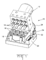
- Figure 1 is a view of the hydraulic unit in which the hydraulic unit containing the pump and valves with the hydraulic control unit shown partially removed to depict the coils and the valves.
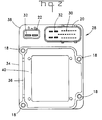
- Figure 2 is a top plan view of the interior of a first embodiment of the peripheral housing frame in which the coil is mounted and to which the hydraulic actuator subassembly and the electronic control subassembly will be mounted.
- Figure 3 is a sectional view of the peripheral mounting frame to which a top loaded coil printed circuit board is mounted.
- Figure 4 is a sectional view similar to section 3 showing the assembly of the coil printed circuit board and the electronics control unit printed circuit board to the peripheral frame.
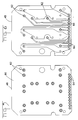
- Figure 5 is a view of one surface of the coil printed circuit board showing a substantially continuous conduction layer which serves as an electrical shield.
- Figure 6 is a view of the opposite solder side of the coil printed circuit board showing the traces connecting individual coils to terminals for connecting the coils to the electronic control unit.
- Figure 7 is a view similar to the view of Figure 3, but showing an embodiment in which the coil printed circuit board is mounted from the bottom.
- Figure 8 is a sectional view similar to Figure 4 showing of the components of the embodiment of Figure 7 in their assembled configuration.
- Figure 9 is a view taken on the lines 9-9 of Figure 10 of an insert molded wiring board which can be used instead of a conventional fiberglass printed circuit baord laminate.
- Figure 10 is a sectional view of the insert molded wiring board taken along section lines 10-10 in Figure 9.
- the electronically controlled hydraulic unit 10 shown in Figure 1 is intended for use in an anti-lock braking system in an automobile.
- the hydraulic actuator unit, subassembly or pump 12 is shown partially removed to expose the interior of the unit. More specifically the orientation of Figure 1 is intended to show the valve actuators 14 on the hydraulic unit 12 and the solenoid coils 16.
- the pump 12 and the valve subassembly containing valves 14 are part of the same hydraulic actuator subassembly.
- the valve actuators 14 are refereed to as domes and comprise generally cylindrical members.
- valve actuators When the unit is properly assembled, these valve actuators extend through the center of the toroidal coils 16 so that the magnetic field induced by the application of an electrical current to the coils 16 causes the valve located in the corresponding valve actuator member 14 to move between a seated and an unseated position.
- Bosses 18 which receive conventional fastening members, not shown are shown on the exterior of the body of the assembly. For example bolts extending upward through bosses 18 could be used to attach the hydraulic subassembly 10 in position. Other conventional fastening means, such as clamps, or other similar devices known to one skilled in the art could also be employed.
- the hydraulic unit 10 also includes an input output connector 20 located on the exterior of the coil chamber in which the coils 16 are located.
- This electrical connector 20 provides for the input and output of both electrical power and signal currents to the device.
- a second connector in the form of header 22 mates with connector 24 to deliver power over external cable 26 to the hydraulic pump 12.
- FIG. 2 is a top plan view of the peripheral coil mounting housing frame 34 of the first embodiment of this invention.
- Signal terminals or pins 30 and power pins 32 in connectors 20 and 22 are visible in this view. These pins can be stitched in the plastic coil mounting housing 34 in a conventional manner.
- the coil mounting housing 34 has continuous peripheral sidewalls 36 extending upward from the base of the housing 34 to form a coil chamber in which a plurality of coils 16 can be located. The sidewalls are shown more clearly in Figure 3.
- the pin header connectors 20 and 22 are located on an extension of the base 38 of the coil mounting housing 34.
- the coil mounting housing 34 also contains a sealing rim 40 consisting of an upwardly facing surface surrounding the central area in which the coils will be positioned. In the embodiment of Figure 2, this sealing rim comprises an upwardly facing surface which extends completely around the inner periphery of the sidewalls 36.
- the exploded section view of Figure 3 shows the components of the coil mounting subassembly 28, the electronic control unit control board 56 and the lower cover 58.
- the coil mounting subassembly 28 comprises the coils 16 mounted to coil printed circuit board 48, which is mounted in the coil mounting housing 34 formed by sidewalls 36, and a resilient seal 42 which maintains sealing integrity between the coil printed circuit board 48 and the coil housing 34.
- a plurality of electrical contact terminals in the form of pins 46 are also mounted on the coil printed circuit board 48. These pins are shown in a conventional single row configuration.
- Each of the coils 16 has two coil leads 50 extending from the bottom. These coil leads are bent to provide resiliency so that the solder joint will not be stressed when a compressive load is applied to the coil in the direction parallel to the axis of the coil. Although not shown, these coils are otherwise conventional in construction.
- a winding on a bobbin is housed in a metallic coil enclosure with the coil leads extending axially from the bottom of the bobbin.
- a coil seal or gasket 52 is positioned between each coil 16 and the printed circuit board 48. In the embodiment shown herein this gasket is secured to the outer periphery of a coil mounting seat 51 which includes a snap in hold down feature 54 extending from the center of the gasket.
- This hold down feature extends through a hold in the coil printed circuit board and secures the coil to the printed circuit board.
- This coil seat can be secured to the printed circuit board and the coil can be subsequently snapped in to engagement with this seat 51.
- the hold down seat can be insert molded to the coil 16 and its outer metal coil housing and the hold down feature 54 can be used to secure the coil 16 to the printed circuit board 48.
- the gasket or seal 52 When the gasket or seal 52 is compressed a seal is formed prohibiting the passage of fluids through the printed circuit board hole in which the hold down is located.
- this seal or gasket 52 also imparts resilience to the coils so that when downward load toward the coil printed circuit board is applied to the coil, the seal or gasket resists that force and urges the coil upward. This significance of this resilience will be subsequently described. It should be understood that the seal or gasket 52 can also be mounted to the coil 16 by insert molding seal to the exterior of the coil body.
- the sidewalls 36 on the coil mounting housing are shown in section in Figure 3.
- Figure 2 shows that these sidewalls are continuous to form a frame or shroud extending around all four sides of the coil cavity defined by the housing 34. This cavity is open on both the top and the bottom of sidewalls 36.
- a sealing rim 40 having an upwardly facing surface extends completely around the inner periphery of the upstanding sidewalls 36. The opening is defined by this sealing rim is smaller than the coil printed circuit board 48 so that the coil printed circuit board overlaps the sealing rim 40 around its entire peripheral length.
- a seal 42 is positioned on the upper surface of the sealing rim 40 between the sealing rim and the coil printed circuit board 48.
- This seal 42 may be a resilient member or it may be a viscous sealing material deposited on the sealing rim. Conventional materials are available to form a suitable seal of this type when placed under compression.
- the coil wiring board subassembly comprising a plurality of coils 16 soldered to the coil printed circuit board 48, is mounted in the coil housing 34 by inserting the coil wiring board subassembly in the open top of the housing 34.
- the coil printed circuit board 48 can then be seated on the sealing rim with the seal 42 maintaining sealing integrity therebetween.
- One or more staking pins 44 extending upwardly from the housing 34 can be bent over to hold the coil printed circuit board securely in place.
- FIG. 4 shows coil subassembly secured to the coil housing 34.
- Figure 4 also shows the assembled configuration of the electronic control printed circuit board 56.
- this printed circuit board contains a number of components, shown here only in representative form. The exact configuration of this control board does not form part of the subject matter of the invention disclosed herein.
- This control board subassembly includes the hardware of the electronic control subassembly or unit.
- pins 46 can be soldered to control board 56 after assembly of the coil board 48 in housing 34.
- the pins in the input/output header 20 can also be soldered to control board 56 after assembly of the coil printed circuit board 48 now forms a sealing bulkhead above the control board 56.
- the tops of coils 16 extend above the upper edge of the sidewalls 36 of the housing frame 34.
- the lip surrounding the base of the valves engage the tops of the metal coil housing of coils 16 forming a tight metal to metal interface.
- the coils are forced down and the resilient coils sealing members 52 exert a force urging the metal coil housings of coils 16 upward into engagement with valve lips. A continuous magnetic flux path is thus formed through the coil housing and the metal valves.
- Figures 5 and 6 show both sides of the double sided coil printed circuit board 48.
- Figure 5 shows the bottom or solder side of the board. Plated through holes 62 are provided so that the coils 16 can be soldered to this board.
- Header 64 is a connector with a plurality of terminals or pins 46 soldered to the printed circuit board 48. These pins can be soldered in plated through holes which are obstructed by the presence of the header in Figure 5.
- Substantially all of the side of the printed circuit board 48 shown in Figure 5 has a substantially continuous conductive surface 60 which can serve as a shield. In the preferred embodiment, this conductive surface 60 comprises a layer of copper deposited on the insulative substrate.
- this copper layer surrounding the plated through holes 62 have been etched to provide an annular insulating area surrounding the solder joints connecting the coils 16 and the pins 46 to the plated though holes.
- This conductive layer can serve as a shield since it is positioned on one side of the control printed circuit board 56. This conductive layer could also serve as a ground plane. The electronic circuits on this control board can thus be shielded from electromagnetic radiation along this side of the assembly. Alternatively this shield would also prevent radiation emanating form the electronic control circuit from affecting other components.
- Figure 6 shows the opposite coil mounting or component side of printed circuit board 48.
- the traces 66 which would connect the coils 16 to the pins 46 are shown in Figure 6.
- this printed circuit board would be a conventional 0.062 inch thick FR-4 printed circuit board. Alternatively thicker boards could be employed.
- Figures 7 and 8 show an alternative version of assembly in which the printed circuit board 148 is mounted to the peripheral housing frame 134 from the bottom instead of from the top as in the embodiment of Figures 2-6.
- Figures 7 and 8 show the bottom mounted embodiment in a fashion analogous to the way that Figures 3 and 4 show the top mounted embodiment.
- the sealing rim 140 comprises a downwardly facing annular surface along which the seal 142 is located. This seal 142 engages the top surface or component side of the coil printed circuit board 148.
- the terminals or pins 146 are not initially mounted in a printed circuit board header as for the top mounted version. In this embodiment the pins 146 are stitched in the housing 134 using a conventional terminal assembly stitching machine.
- the first and second embodiments of this invention show the use of a conventional copper laminate printed circuit board. These printed circuit boards comprise only one type of wiring board which can be employed.
- Figures 9 and 10 show an insert molded wiring board 248 in which a stamped and formed lead frame is used. Insert molding in a conventional operation in which the lead frame is mounted in a mold and then plastic is injected around the lead frame. Portions of the lead frame are then severed to form distinct traces which serve the same purpose as traces on conventional printed circuit boards. As shown in Figure 9 these lead frame traces include holes 262 through which coil leads 52 can be inserted. Solder pads, which are integral portions of the lead frame traces, surround these holes and the coil leads can be soldered directly to these pads in conventional fashion.
- the pins 246 are also integral portions of the lead frame which have been formed at right angles to the portion of the lead frame which forms the traces.
- Plastic has been insert molded around portions of the pin 246 leaving the ends of the pins exposed for soldering to the control board.
- This plastic surrounding pins 246 can serve as wiring board separators and it also serves to secure the lead frame to the plastic substrate.
- the insert molded wiring board 248 of the type shown in the embodiment of Figures 9 and 10 can be substituted directly for the printed circuit boards 48 and 148 of the first two embodiments.
- the assembly operations of both embodiments of this invention are conventional and these components are reliably manufacturable.
- the components are first soldered to the wiring or printed circuit board using conventional soldering operations.
- the components can be wave soldered. If the first embodiment is wave soldered, a secondary operation will be necessary to remove solder deposited on the pins 46. This operation can be performed with a hot air knife and is a conventional operation.
- solder paste can be deposited on printed circuit pads adjacent to the plated through holes, and a surface mount operation, such as reflow soldering can be used to solder the coils and the pins to the printed circuit board.
- solder paste can be deposited on printed circuit pads adjacent to the plated through holes, and a surface mount operation, such as reflow soldering can be used to solder the coils and the pins to the printed circuit board.
- the seals 24 can be molded elastomer seals or a viscous sealant can be deposited along the sealing rim. This sealant can also be an adhesive.
- the materials used for the seal are conventional and readily available.
- the housing frame is an injection molded member which can be easily fabricated. No special materials are necessary. Pins 46, 146 or 246 can also be soldered to the control boards 56 and 156 can be soldered using conventional techniques.
Landscapes
- Engineering & Computer Science (AREA)
- Physics & Mathematics (AREA)
- Mechanical Engineering (AREA)
- Fluid Mechanics (AREA)
- General Engineering & Computer Science (AREA)
- Electromagnetism (AREA)
- Transportation (AREA)
- Magnetically Actuated Valves (AREA)
- Regulating Braking Force (AREA)
- Reciprocating Pumps (AREA)
- Connection Of Motors, Electrical Generators, Mechanical Devices, And The Like (AREA)
Applications Claiming Priority (2)
| Application Number | Priority Date | Filing Date | Title |
|---|---|---|---|
| US08/320,621 US5452948A (en) | 1994-10-07 | 1994-10-07 | Apparatus and method for electronically controlled hydraulic actuator |
| US320621 | 1994-10-07 |
Publications (1)
| Publication Number | Publication Date |
|---|---|
| EP0705747A1 true EP0705747A1 (fr) | 1996-04-10 |
Family
ID=23247220
Family Applications (1)
| Application Number | Title | Priority Date | Filing Date |
|---|---|---|---|
| EP95306925A Ceased EP0705747A1 (fr) | 1994-10-07 | 1995-09-29 | Actionneur hydraulique commandé électronique |
Country Status (6)
| Country | Link |
|---|---|
| US (1) | US5452948A (fr) |
| EP (1) | EP0705747A1 (fr) |
| JP (1) | JPH08121323A (fr) |
| KR (1) | KR960013894A (fr) |
| CN (1) | CN1122759A (fr) |
| BR (1) | BR9504318A (fr) |
Cited By (6)
| Publication number | Priority date | Publication date | Assignee | Title |
|---|---|---|---|---|
| EP0736429A3 (fr) * | 1995-04-05 | 1998-04-29 | Lucas Industries Public Limited Company | Unité hydraulique pour système de freinage antiblocage |
| DE19728303A1 (de) * | 1997-07-03 | 1999-01-07 | Itt Mfg Enterprises Inc | Elektrohydraulische Druckregelvorrichtung |
| EP2127976A3 (fr) * | 2008-05-27 | 2010-07-07 | Nissin Kogyo Co., Ltd. | Unité de commande électronique et dispositif de contrôle du comportement d'un véhicule |
| EP2703241A1 (fr) | 2012-08-31 | 2014-03-05 | Continental Teves AG & Co. oHG | Unité de contrôle électronique pour systèmes de frein de véhicule automobile |
| DE102012215516A1 (de) | 2012-08-31 | 2014-03-06 | Continental Teves Ag & Co. Ohg | Ventilspulenmodul für Kraftfahrzeugbremssysteme |
| DE102015211465A1 (de) | 2015-01-30 | 2016-08-04 | Conti Temic Microelectronic Gmbh | Steuergerät für ein Kraftfahrzeugbremssystem |
Families Citing this family (45)
| Publication number | Priority date | Publication date | Assignee | Title |
|---|---|---|---|---|
| DE69306520T2 (de) * | 1992-10-06 | 1997-04-17 | Sumitomo Electric Industries, Ltd., Osaka | Antiblockier-Bremssystem |
| EP0742765B1 (fr) * | 1994-02-10 | 1998-04-22 | Lucas Industries Public Limited Company | Dispositif de freinage a systeme antiblocage |
| US6000128A (en) * | 1994-06-21 | 1999-12-14 | Sumitomo Special Metals Co., Ltd. | Process of producing a multi-layered printed-coil substrate |
| US5766026A (en) * | 1994-10-07 | 1998-06-16 | The Whitaker Corporation | Electrical connector assembly with sealed and spring biased electrical component |
| US5758931A (en) * | 1995-03-30 | 1998-06-02 | Sumitomo Wiring Systems, Ltd. | Electric control unit integrated with a hydraulic unit in an anti-lock brake system |
| KR100216995B1 (ko) * | 1995-10-23 | 1999-09-01 | 나카타니 사쿠쇼 | 액압제어장치 |
| US5785394A (en) * | 1996-05-24 | 1998-07-28 | Ford Global Technologies, Inc. | Solenoid assembly for anti-lock braking system |
| WO1997047502A1 (fr) * | 1996-06-12 | 1997-12-18 | Kelsey Hayes Company | Connecteur interne de moteur de systeme d'antiblocage de freins |
| JPH1059152A (ja) * | 1996-08-26 | 1998-03-03 | Nisshinbo Ind Inc | 液圧制御装置 |
| DE59808408D1 (de) * | 1997-04-16 | 2003-06-26 | Siemens Ag | Ventilsteuergerät |
| DE19732038A1 (de) * | 1997-07-25 | 1999-01-28 | Itt Mfg Enterprises Inc | Motorangetriebenes Aggregat |
| JPH11167954A (ja) * | 1997-12-02 | 1999-06-22 | Nisshinbo Ind Inc | コネクタ装置の電気的接続構造 |
| JPH11165627A (ja) * | 1997-12-04 | 1999-06-22 | Sumitomo Electric Ind Ltd | 車両用ブレーキ液圧制御装置 |
| US6000679A (en) * | 1997-12-11 | 1999-12-14 | General Motors Corporation | Solenoid coil attachment mechanism |
| JP3627485B2 (ja) * | 1997-12-17 | 2005-03-09 | 三菱電機株式会社 | 車両用圧力制御装置 |
| US6059381A (en) * | 1997-12-19 | 2000-05-09 | Itt Manufacturing Enterprises, Inc. | ABS pump connector |
| US5992946A (en) * | 1997-12-19 | 1999-11-30 | Itt Manufacturing Enterprises, Inc. | ABS pump connector |
| JP2000127934A (ja) * | 1998-10-23 | 2000-05-09 | Unisia Jecs Corp | アンチロックブレーキ装置の液圧ユニット |
| JP3456426B2 (ja) * | 1998-11-24 | 2003-10-14 | 住友電気工業株式会社 | 電子制御ユニット |
| US6183408B1 (en) * | 1999-05-03 | 2001-02-06 | Beckman Coulter, Inc. | Rotor shaft assembly having non-linear stiffness |
| JP2001044024A (ja) * | 1999-08-03 | 2001-02-16 | Nisshinbo Ind Inc | 圧力制御装置 |
| US6241489B1 (en) | 1999-10-08 | 2001-06-05 | Kelsey-Hayes Company | Internal electrical connector for a hydraulic control unit |
| DE19955603C1 (de) * | 1999-11-18 | 2001-02-15 | Siemens Ag | Steuergerät für ein Kraftfahrzeug und Herstellungsverfahren |
| FR2804574B1 (fr) * | 2000-01-28 | 2004-07-23 | Siemens Automotive Sa | Boitier de commande pour dispositif d'antiblocage |
| US6485112B1 (en) | 2001-06-13 | 2002-11-26 | Trw Inc. | Assembly, with lead frame, for antilock brake system and associated method |
| DE10161230B4 (de) * | 2001-12-13 | 2012-03-15 | Robert Bosch Gmbh | Einbaueinheit für eine Getriebesteuerung eines Kraftfahrzeuges |
| JP4102624B2 (ja) * | 2002-09-12 | 2008-06-18 | 株式会社大井製作所 | 配線板がインサート成形されたプラスチック部品の接合構造 |
| EP1618313B1 (fr) * | 2003-04-30 | 2020-12-02 | Goodrich Corporation | Frein electrique destine a un aeronef |
| US7011113B2 (en) * | 2004-03-04 | 2006-03-14 | Sauer-Danfoss Inc. | Hydraulic cartridge valve solenoid coil for direct mount to a printed circuit board |
| JP2006027528A (ja) * | 2004-07-20 | 2006-02-02 | Advics:Kk | 車両用ブレーキ液圧制御装置 |
| KR20070116803A (ko) * | 2005-04-07 | 2007-12-11 | 루크 라멜렌 운트 쿠플룽스바우베타일리궁스 카게 | 전자 유압식 제어 장치 |
| US20080089044A1 (en) * | 2006-10-16 | 2008-04-17 | Raybestos Powertrain, Llc | Spacer block for rebuilt electrically operated automatic transmission controller assembly |
| DE102007055728A1 (de) * | 2006-12-15 | 2008-06-19 | Advics Co., Ltd., Kariya | Fluiddrucksteuervorrichtung |
| DE102007056430A1 (de) * | 2007-11-23 | 2009-05-28 | Knorr-Bremse Systeme für Nutzfahrzeuge GmbH | Verfahren zur Herstellung einer pneumatischen Einrichtung eines Fahrzeugs aus Kunststoffteilen |
| WO2010033827A1 (fr) * | 2008-09-18 | 2010-03-25 | Advanced Powertrain Engineering, Llc | Ensemble circuit imprimé pour module d'électroaimant de transmission automatique |
| CA2717752C (fr) * | 2009-10-15 | 2018-01-23 | Advanced Powertrain Engineering, Llc | Methode de remise a neuf de solenoides pour boites de vitesses automatiques |
| JP2012158228A (ja) * | 2011-01-31 | 2012-08-23 | Advics Co Ltd | ソレノイド制御装置 |
| US9062791B2 (en) * | 2011-05-23 | 2015-06-23 | Nissin Kogyo Co., Ltd. | Electric connection structure of electromagnetic valve drive assembly, electromagnetic valve drive assembly, and vehicle brake fluid pressure control apparatus |
| JP5974493B2 (ja) * | 2012-01-18 | 2016-08-23 | 株式会社村田製作所 | 圧電ポンプ、圧電ポンプの製造方法 |
| JP2014138518A (ja) * | 2013-01-17 | 2014-07-28 | Sumitomo Wiring Syst Ltd | 電気接続箱 |
| US9970533B2 (en) | 2013-11-27 | 2018-05-15 | Advanced Powertrain Engineering, Llc | Solenoid rebuilding method for automatic transmissions |
| WO2015189610A1 (fr) * | 2014-06-11 | 2015-12-17 | Geoprober Limited | Bloc de vannes modulaire |
| JP6681812B2 (ja) * | 2016-09-20 | 2020-04-15 | 日立オートモティブシステムズ株式会社 | 液圧制御装置およびブレーキ制御装置 |
| FR3058496B1 (fr) | 2016-11-09 | 2019-09-06 | Permaswage | Corps de jonction, raccord, systeme hydraulique pour le passage d'un fluide entre deux circuits hydrauliques, procede de montage associe |
| CN114424408B (zh) * | 2019-09-27 | 2025-08-29 | 东京Cosmos电机株式会社 | 电子器件及电子设备 |
Citations (4)
| Publication number | Priority date | Publication date | Assignee | Title |
|---|---|---|---|---|
| US4697863A (en) * | 1985-10-22 | 1987-10-06 | Amp Incorporated | Electrical connector assembly for antiskid braking system |
| WO1992012878A1 (fr) * | 1991-01-15 | 1992-08-06 | Alfred Teves Gmbh | Regulateur electrohydraulique de pression |
| EP0499670A1 (fr) * | 1991-02-20 | 1992-08-26 | Siemens Aktiengesellschaft | Dispositif de commande de valves |
| EP0604111A2 (fr) * | 1992-12-21 | 1994-06-29 | Sumitomo Wiring Systems, Ltd. | Système de freinage à anti-blocage |
Family Cites Families (2)
| Publication number | Priority date | Publication date | Assignee | Title |
|---|---|---|---|---|
| US4785532A (en) * | 1985-10-22 | 1988-11-22 | Amp Incorporated | Method of making electrical connector assembly for antiskid braking system |
| JPH04127057A (ja) * | 1990-09-18 | 1992-04-28 | Michinao Mizugaki | 医薬品製剤の結晶化度の測定方法 |
-
1994
- 1994-10-07 US US08/320,621 patent/US5452948A/en not_active Expired - Fee Related
-
1995
- 1995-09-27 CN CN95116050A patent/CN1122759A/zh active Pending
- 1995-09-29 EP EP95306925A patent/EP0705747A1/fr not_active Ceased
- 1995-09-29 KR KR1019950032735A patent/KR960013894A/ko not_active Abandoned
- 1995-10-06 JP JP7260271A patent/JPH08121323A/ja not_active Withdrawn
- 1995-10-06 BR BR9504318A patent/BR9504318A/pt not_active Application Discontinuation
Patent Citations (4)
| Publication number | Priority date | Publication date | Assignee | Title |
|---|---|---|---|---|
| US4697863A (en) * | 1985-10-22 | 1987-10-06 | Amp Incorporated | Electrical connector assembly for antiskid braking system |
| WO1992012878A1 (fr) * | 1991-01-15 | 1992-08-06 | Alfred Teves Gmbh | Regulateur electrohydraulique de pression |
| EP0499670A1 (fr) * | 1991-02-20 | 1992-08-26 | Siemens Aktiengesellschaft | Dispositif de commande de valves |
| EP0604111A2 (fr) * | 1992-12-21 | 1994-06-29 | Sumitomo Wiring Systems, Ltd. | Système de freinage à anti-blocage |
Non-Patent Citations (1)
| Title |
|---|
| "Neues ABS von Teves", KRAFTHAND, vol. 66, no. 20, 23 October 1993 (1993-10-23), pages 1618/1619 - 1619, XP000403351 * |
Cited By (9)
| Publication number | Priority date | Publication date | Assignee | Title |
|---|---|---|---|---|
| EP0736429A3 (fr) * | 1995-04-05 | 1998-04-29 | Lucas Industries Public Limited Company | Unité hydraulique pour système de freinage antiblocage |
| DE19512804C2 (de) * | 1995-04-05 | 2000-06-15 | Lucas Ind Plc | Hydraulikaggregat für eine blockiergeschützte Fahrzeugbremsanlage |
| DE19728303A1 (de) * | 1997-07-03 | 1999-01-07 | Itt Mfg Enterprises Inc | Elektrohydraulische Druckregelvorrichtung |
| EP2127976A3 (fr) * | 2008-05-27 | 2010-07-07 | Nissin Kogyo Co., Ltd. | Unité de commande électronique et dispositif de contrôle du comportement d'un véhicule |
| US8783794B2 (en) | 2008-05-27 | 2014-07-22 | Nissin Kogyo Co., Ltd. | Electronic control unit and vehicle behavior control device |
| US9221438B2 (en) | 2008-05-27 | 2015-12-29 | Nissin Kogyo Co., Ltd. | Electronic control unit and vehicle behavior control device |
| EP2703241A1 (fr) | 2012-08-31 | 2014-03-05 | Continental Teves AG & Co. oHG | Unité de contrôle électronique pour systèmes de frein de véhicule automobile |
| DE102012215516A1 (de) | 2012-08-31 | 2014-03-06 | Continental Teves Ag & Co. Ohg | Ventilspulenmodul für Kraftfahrzeugbremssysteme |
| DE102015211465A1 (de) | 2015-01-30 | 2016-08-04 | Conti Temic Microelectronic Gmbh | Steuergerät für ein Kraftfahrzeugbremssystem |
Also Published As
| Publication number | Publication date |
|---|---|
| US5452948A (en) | 1995-09-26 |
| CN1122759A (zh) | 1996-05-22 |
| BR9504318A (pt) | 1996-10-08 |
| JPH08121323A (ja) | 1996-05-14 |
| KR960013894A (ko) | 1996-05-22 |
Similar Documents
| Publication | Publication Date | Title |
|---|---|---|
| US5452948A (en) | Apparatus and method for electronically controlled hydraulic actuator | |
| US5766026A (en) | Electrical connector assembly with sealed and spring biased electrical component | |
| US6791170B1 (en) | Onboard semiconductor device | |
| US6155856A (en) | Electronic control unit with electrical connector | |
| US7120030B2 (en) | Housing structure of vehicle-mounted electronic equipment | |
| US5449227A (en) | Solenoid attachment for antilock brake system | |
| US5624277A (en) | Filtered and shielded electrical connector using resilient electrically conductive member | |
| JPH10132122A (ja) | 電磁弁ユニット | |
| US5474108A (en) | Electromagnetic valve unit | |
| EP1581036A2 (fr) | Procédé de fabrication d'un module électronique étanche | |
| US5412340A (en) | Shield structure for use in microwave circuit device | |
| KR100759724B1 (ko) | 제거가능한 커넥터를 위한 전자 제어 모듈 및 그 조립 방법 | |
| US20200137904A1 (en) | Circuit device, method for manufacturing circuit device and connector | |
| US6655989B1 (en) | Environmentally sealed electrical connector system | |
| EP3067992A1 (fr) | Ensemble connecteur électrique, composant électronique et procédé d'assemblage | |
| US11343921B2 (en) | Electronic unit | |
| CN111316505B (zh) | 电路装置 | |
| EP1737286A2 (fr) | Module électronique hermétique à plusieurs circuits sans moyen de fixation, méthode de fabrication | |
| US11239602B2 (en) | ECU assembly with rotating PCB | |
| US5785394A (en) | Solenoid assembly for anti-lock braking system | |
| JP2009070887A (ja) | 電気機器 | |
| EP0854667B1 (fr) | Module de commande électronique | |
| US20240314945A1 (en) | Sealed ecu assembly | |
| KR200302435Y1 (ko) | 하이브리드 정션박스 | |
| JP4375924B2 (ja) | シールド線の接続部の構造 |
Legal Events
| Date | Code | Title | Description |
|---|---|---|---|
| PUAI | Public reference made under article 153(3) epc to a published international application that has entered the european phase |
Free format text: ORIGINAL CODE: 0009012 |
|
| AK | Designated contracting states |
Kind code of ref document: A1 Designated state(s): DE FR GB |
|
| 17P | Request for examination filed |
Effective date: 19960927 |
|
| 17Q | First examination report despatched |
Effective date: 19970711 |
|
| GRAG | Despatch of communication of intention to grant |
Free format text: ORIGINAL CODE: EPIDOS AGRA |
|
| STAA | Information on the status of an ep patent application or granted ep patent |
Free format text: STATUS: THE APPLICATION HAS BEEN REFUSED |
|
| 18R | Application refused |
Effective date: 19990130 |