EP0499719A1 - Digitales Bildwiedergabesystem - Google Patents
Digitales Bildwiedergabesystem Download PDFInfo
- Publication number
- EP0499719A1 EP0499719A1 EP91200361A EP91200361A EP0499719A1 EP 0499719 A1 EP0499719 A1 EP 0499719A1 EP 91200361 A EP91200361 A EP 91200361A EP 91200361 A EP91200361 A EP 91200361A EP 0499719 A1 EP0499719 A1 EP 0499719A1
- Authority
- EP
- European Patent Office
- Prior art keywords
- job
- pages
- reproduction
- printing
- copy
- Prior art date
- Legal status (The legal status is an assumption and is not a legal conclusion. Google has not performed a legal analysis and makes no representation as to the accuracy of the status listed.)
- Granted
Links
- 230000015654 memory Effects 0.000 claims description 107
- 230000009471 action Effects 0.000 claims description 16
- 230000008859 change Effects 0.000 claims description 7
- 238000003860 storage Methods 0.000 claims description 5
- 230000001419 dependent effect Effects 0.000 claims description 2
- 238000007599 discharging Methods 0.000 claims description 2
- 238000012544 monitoring process Methods 0.000 claims description 2
- 238000012360 testing method Methods 0.000 abstract description 31
- 230000002452 interceptive effect Effects 0.000 abstract description 7
- 230000006870 function Effects 0.000 description 32
- 238000000034 method Methods 0.000 description 9
- 230000000994 depressogenic effect Effects 0.000 description 6
- 238000010586 diagram Methods 0.000 description 6
- 230000008569 process Effects 0.000 description 6
- 238000012545 processing Methods 0.000 description 6
- 230000000694 effects Effects 0.000 description 4
- 238000004519 manufacturing process Methods 0.000 description 4
- 238000003825 pressing Methods 0.000 description 3
- 230000009467 reduction Effects 0.000 description 3
- 230000032683 aging Effects 0.000 description 2
- 230000005540 biological transmission Effects 0.000 description 2
- 239000003086 colorant Substances 0.000 description 2
- 230000003247 decreasing effect Effects 0.000 description 2
- 238000003780 insertion Methods 0.000 description 2
- 230000037431 insertion Effects 0.000 description 2
- 238000012546 transfer Methods 0.000 description 2
- 230000003213 activating effect Effects 0.000 description 1
- 238000003491 array Methods 0.000 description 1
- 230000015572 biosynthetic process Effects 0.000 description 1
- 230000000881 depressing effect Effects 0.000 description 1
- 238000001514 detection method Methods 0.000 description 1
- 238000009826 distribution Methods 0.000 description 1
- 239000004973 liquid crystal related substance Substances 0.000 description 1
- 238000012986 modification Methods 0.000 description 1
- 230000004048 modification Effects 0.000 description 1
- 238000011022 operating instruction Methods 0.000 description 1
- 230000003287 optical effect Effects 0.000 description 1
- 230000004044 response Effects 0.000 description 1
Images


Classifications
-
- H—ELECTRICITY
- H04—ELECTRIC COMMUNICATION TECHNIQUE
- H04N—PICTORIAL COMMUNICATION, e.g. TELEVISION
- H04N1/00—Scanning, transmission or reproduction of documents or the like, e.g. facsimile transmission; Details thereof
- H04N1/32—Circuits or arrangements for control or supervision between transmitter and receiver or between image input and image output device, e.g. between a still-image camera and its memory or between a still-image camera and a printer device
- H04N1/32502—Circuits or arrangements for control or supervision between transmitter and receiver or between image input and image output device, e.g. between a still-image camera and its memory or between a still-image camera and a printer device in systems having a plurality of input or output devices
- H04N1/32507—Circuits or arrangements for control or supervision between transmitter and receiver or between image input and image output device, e.g. between a still-image camera and its memory or between a still-image camera and a printer device in systems having a plurality of input or output devices a plurality of input devices
- H04N1/32512—Circuits or arrangements for control or supervision between transmitter and receiver or between image input and image output device, e.g. between a still-image camera and its memory or between a still-image camera and a printer device in systems having a plurality of input or output devices a plurality of input devices of different type, e.g. internal and external devices
-
- H—ELECTRICITY
- H04—ELECTRIC COMMUNICATION TECHNIQUE
- H04N—PICTORIAL COMMUNICATION, e.g. TELEVISION
- H04N1/00—Scanning, transmission or reproduction of documents or the like, e.g. facsimile transmission; Details thereof
- H04N1/00912—Arrangements for controlling a still picture apparatus or components thereof not otherwise provided for
- H04N1/00915—Assigning priority to, or interrupting, a particular operation
-
- H—ELECTRICITY
- H04—ELECTRIC COMMUNICATION TECHNIQUE
- H04N—PICTORIAL COMMUNICATION, e.g. TELEVISION
- H04N1/00—Scanning, transmission or reproduction of documents or the like, e.g. facsimile transmission; Details thereof
- H04N1/32—Circuits or arrangements for control or supervision between transmitter and receiver or between image input and image output device, e.g. between a still-image camera and its memory or between a still-image camera and a printer device
- H04N1/32561—Circuits or arrangements for control or supervision between transmitter and receiver or between image input and image output device, e.g. between a still-image camera and its memory or between a still-image camera and a printer device using a programmed control device, e.g. a microprocessor
-
- H—ELECTRICITY
- H04—ELECTRIC COMMUNICATION TECHNIQUE
- H04N—PICTORIAL COMMUNICATION, e.g. TELEVISION
- H04N2201/00—Indexing scheme relating to scanning, transmission or reproduction of documents or the like, and to details thereof
- H04N2201/0077—Types of the still picture apparatus
- H04N2201/0081—Image reader
-
- H—ELECTRICITY
- H04—ELECTRIC COMMUNICATION TECHNIQUE
- H04N—PICTORIAL COMMUNICATION, e.g. TELEVISION
- H04N2201/00—Indexing scheme relating to scanning, transmission or reproduction of documents or the like, and to details thereof
- H04N2201/0077—Types of the still picture apparatus
- H04N2201/0082—Image hardcopy reproducer
Definitions
- the present invention relates to a digital image reproduction system including:
- the digital copier may be provided with additional input channels through which the copier can directly receive digital image data from other sources such as a workstation or a data transmission network. In this way, a complex image reproduction system is achieved which lends itself to a large variety of different applications.
- the digital copying machine further offers the possibility to process the digital image data by means of a so called digital image processing unit before they are printed-out, so that the quality of the copies can be improved or the appearance of the printed image scan be modified.
- the brightness and contrast of the printed copies or the reproduction scale can easily be adjusted with high accuracy by applying simple and quick image processing routines.
- the digital image reproduction system can be provided advantageously with an interactive user interface for examination and adjustment of the brightness and contrast of the copies, and a further control of the reproduction processes.
- the digital copying machine is equipped with a memory for storing the image data, multiple copies of a document can be formed by scanning the original document only once and using the stored image data for printing as many copies as desired. Due to this feature, the digital copying machine is particularly usable as a so called product copier which is adapted to form large numbers of copies at high speed. Since the scanning section and the printing section of a digital copier operate substantially independently of each other, it is further possible to scan-in a new copying job and to adjust the printing parameters such as brightness, number of desired copies and the like while the printing section is still printing copies of a previous job.
- US-A-4 099 860 describes an electrophotographic copier in which such an interrupt function is implemented. If the user wishes to interrupt a running job for making a number of interrupt copies, he presses an interrupt button, where upon the copying process in the copier is stopped and the printing parameters for the running job are stored in a memory. Then, the user enters the parameters for the intermediate job, feeds-in the original document for this job and restarts the copier which can be regarded as a time-consuming action. After the intermediate job has been completed, the copier automatically retrieves the stored parameters and continues with the interrupted job.
- the image reproduction system comprises memory means for storing the image data and reproduction parameters for a plurality of jobs
- the control system is so designed that it can switch-over from one job to another each time the printer has completed a page or a predefined cluster of pages, it is possible to produce copies of different jobs in an interleaving manner without interrupting the operation of the printing means.
- the printing means may comprise a belt-type photoconductor on which a plurality of image receiving sections are arranged at narrow spacings.
- the photoconductor belt is continuously driven at a comparatively high speed, and the image receiving sections are sequentially exposed by means of, for example, a laser device the laser signal of which is modulated in accordance with the image data received from the memory means.
- the image receiving section for a specific page has been exposed, the time in which the clearance between the trailing edge of the exposed image receiving section and the leading edge of the subsequent image receiving section moves past the laser device is sufficient for the control system to switch over to a different memory location which is associated with a different job. Accordingly, the printing means may be switched-over from one job to another without leaving any blank spaces on the photoconductor belt.
- clusters consisting of a plurality of pages which are to be printed immediately one after the other.
- a cluster may consists of the two pages of a double-sided copy, or, if the copies of a multi-page document are to be stapled, it may consist of the set of pages forming a complete single copy of the document.
- canceling of data means erasing the corresponding memory location or permitting the data to be replaced with new data.
- the memory location can be used for storing the data of a subsequent job, so that the storage capacity of the memory is efficiently used.
- the stored printing parameters for a given job may be cancelled as soon as the job has been completed.
- control system can be switched into an "immediate copy" mode, in which the so called “main copy” mode for performing a running job is interrupted for printing an interrupt copy or copies of a selected other job assigned with a higher priority, and in which the data for the selected job, i.e. the so-called priority job, are held even after the interrupt copies have been completed.
- This feature is particularly useful for making a test copy when the printing parameters for a subsequent job are adjusted. Since the image data and the printing parameters are held in the memory, the user may examine the test copy and may readjust subsequently the printing parameters so as to optimise the quality of the copies.
- the digital image reproduction system can be provided advantageously with a "photo-button".
- the re-adjustment of the printing parameters can simply involve the touching of the photo-button. If the test copies are satisfactory, they may readily be taken as the final copies or, if multiple copies are desired, the system may be programmed to print the required number of copies either immediately or after the interrupted job has been completed.
- the running job is interrupted only for the time required for making the test copy or the test copies.
- the system continues with the previous job, so that the printer is used most effectively without any lost of time.
- the operation of the system can be facilitated by providing an "interrupt copy” button which has a function similar to that of a "print” button of a usual copier but may be depressed even while the copier is busy with a previous job.
- the interrupt copy button When the interrupt copy button is depressed, the system is switched to the immediate copy mode and prints an interrupt copy of a new job.
- the memory is capable of storing a plurality of jobs, the system may be so designed that it automatically takes the last job that has been scanned-in and for which the printing parameters have been entered as the job from which the interrupt copy is to be made. If the interrupt copy button is depressed before the desired number of copies have been entered, the system will produce only a single test copy, since the default setting for the desired number of copies is "1".
- the system wil print the desired number of copies, i.e. execute the complete job, before resuming the main copy mode for the previous job. If the user wishes to make a test copy only of the first page of a document or of specific pages for which the adjustment of the printing parameters must be expected to be critical (e.g. because of low contrast or dark background), he may first make a test copy only of the desired page or pages and then scan-in and copy the complete job after the printing parameters have been properly adjusted.
- the immediate copy mode may be used for printing separately the "critical" pages of a complete job while the rest of the job or a complete job is printed afterwards in the normal mode.
- the image reproduction system according to the invention may thus be designed as a product copier for mass production of large numbers of copies and never the less can be used for making high-quality copies of specific documents.
- the digital image reproduction system may be provided with a "ready" button or with a reset unit for automatically cancelling the immedidate copy mode if the reproduction parameters have not been changed within a predetermined time interval.
- these two criteria for cancelling the immediate copy mode are combined by an OR function.
- the reproduction system according to the invention is preferably provided with a plurality of discharge ports for separately discharging the copies of the individual jobs.
- the copies produced in the immediate copy mode are preferably directed to a special discharge port which is positioned close to the operating panel, so that the user can readily take out and examine the test copies.
- the system as described above offers the possibility to handle a plurality of jobs simultaneously on a time-sharing basis. This is particularly advantageous in a case where a very large number of copies have to be made from two or more different original documents. Then, the copies of both documents may be printed in an interleaving manner so that first copies of both documents are available within a short time.
- the time sharing system may also be used for making the copies in the immediate copy mode concurrently with the copies of the running job. In this way, it can be assured that a rather long job will be is completed within a reasonable time even if the job is frequently interrupted by immediate jobs printed in the immediate copy mode.
- the printing section may cyclically be switched to the different jobs so that one copy or cluster of copies of each job is printed in each cycle.
- the system can advantageously be operated in such a manner that the data received form the network or the workstation are only shortly buffered in the memory of the reproduction system and are printed-out with a higher priority than the scanned-in job (but possibly with a lower priority than the immediate copy mode).
- the reproduction system is permanently in the receiving state in which it may receive data from the network the data received from the network and buffered in the memory can be regarded as a job with a "floating" number of pages. Then, a specific amount of storage capacity of the memory should be reserved for this job. If the reserved memory space is occupied to more than a specific percentage, the priority of weight factor assigned to the "network job" may be automatically increased on the cost of other jobs so as to avoid an overflow of the memory.
- the digital image reproduction system as described therein before can be provided advantageously with an interactive user interface which permits the user to select a specific job from a number of jobs that have been scanned-in and to select different printing parameters for the individual pages of this job, and further to examine and readjust, if necessary, the parameter setting of the selected pages on the basis of the respective images on a display.
- the priority job and the pages from which test copies have to be made can be selected by means of the user interface.
- the user interface is adapted to display a video image of a document sheet that has been scanned-in by the digital image reproduction system after that document sheet has been placed on the exposure platen of the system. If the user changes the operating parameters of the system, for example, if he selects a different reduction scale or readjusts the position of the image on the receiving paper, the video image is adjusted accordingly.
- the display provides a preview of the resultant copy prior to the formation of the hard copy.
- the user interface to be described hereinafter permits the operator to preview a plurality of pages of a scanned document simulta neously and to adjust the operating parameters of the reproduction system separately for each page.
- the images of the pages displayed may be compared to each other and may be adjusted so as to achieve a uniform appearance even when the images on the source documents are non-uniform.
- the interactive user interface as mentioned before is particularly applicable to a digital image reproduction system in which the pages of an original document are sequentially scanned and the image data are stored in page-sized image memories so that they may be readily displayed on the display of the user interface and may be printed-out after the appropriate adjustments have been made.
- a system may be equipped with digital image processing means which provide powerful editing functions. Since the scanning section and the printing section operate independently of each other, it is possible to scan-in a new job and to make the required adjustment operations therefor while the copies of the previous job are still being printed. Further, the digital image reproduction system can receive digital image data from remote devices such as facsimile transmitters, workstations and the like, and is thus particularly suited for combining documents from a variety of sources.
- the display device of the user interface is formed by a touch-sensitive screen on which dialog frames and reduced images of the scanned pages are displayed, and the selection of pages and the input of instructions is achieved by touching the images of the desired pages and command buttons displayed in the dialog frames.
- the reduction scale of the pages displayed on the screen is so selected that a sufficient number of pages are shown side by side and the layout of each page is still perceptible.
- the screen images of the pages are animated to symbolize the print mode that has been selected by the user and/or the operating status of the reproduction system.
- the dialog frames displayed on the screen are buttons and are so structured that only those command buttons are shown on the screen which are needed for the selected adjustment operation and are actually executable under the present operating conditions.
- This dialog structure avoids that an occasional user of the reproduction system is puzzled by a large variety of command buttons. Instead, the user is only confronted with the options which are actually available in the present situation and is guided through the adjustment procedure wherein the images of the document pages displayed on the screen provide immediate feedback of the effect of each adjustment operation.
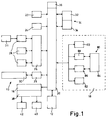
- a digital copier is generally comprised of a number of input channels 10 for inputting digital image data, a digital image processeor or digital image processing unit 12, a memory 14, a printing section 16, a user interface 18 and a control unit 20 for controlling the operation of the printing section 16 and the transfer of data between the input channels 10, the digital image processor 12 the memory 14 and the printing section 16 in accordance with a program or with commands input through the user interface 18.
- the input channels 10 comprise a main scanner 22 equipped preferrably with an automatic document feeder for sequentially scanning a plurality of original document sheets.
- the document feeder may be loaded with a plurality of multi-page documents which are separated from each other for example be separating sheets for distinguishing the document from each other and for handling them as different copying jobs.
- the document feeder is capable of reversing the documents sheets or the main scanner is equipped with two optical scanning sytem for scanning double-sided documents.
- an auxiliary scanner 24 the function of which will be explained now.
- the auxiliary scanner 24 can be used for inputting manually a job that shall be carried out immediately, whithout waiting until the printing section 16 has completed a running job.
- the input channels 10 further comprise a connection port 26 for external workstations 28, a facsimile receiver or the like and a connection port 29 for direct connection with a digital network 30 such as ISDN. If a workstation 28 cooperates with a separate scanner 31, such a scanner can also be used for inputting data.
- the digital image processor 12 is adapted to process and enhance the image data input through the input channels 10.
- a job number to each separate job that has been scanned-in or input, and further a page number to each separate page of the respective job. For example, all the pages which are scanned during a continuous scanning action may form a single job, and the individual pages of this job will get a different page number. Furthermore, specific buttons can be provided in the system for the determination of the extent of a single job.
- the memory 14 is divideable into a plurality of memory sections each of which is associated with a specific printing job.
- Each of these memory sections includes an image memory for storing the image data received through one of the input channels and a parameter memory for storing printing parameters specifying the contrast, brightness, reproduction scale and the like of the copies to be printed.
- the printing parameters may include further parameters relating to the format of the printed images, the level of resolution or to specific options such as insertion of logos and the like.
- the memory 14 is divided inter alia into a main memory 32 and a priority memory 34.
- the priority memory 34 is capable of storing the image data and printing parameters for a specific job, the so-called immediate or priority job which is to be printed with a high priority. This occurs by pushing down a special button, the so-called "interrupt copy button". All other jobs are stored in the main memory 32. It will however be understood that there need not be a physical sub-division of the memory 14 inter alia into the main memory 32 and the priority memory 34. Instead, any memory sections of the memory 14 may be defined as the priority memory 34 if the job stored therein is intended to be treated as the priority job. Such a memory section can be marked by a so-called priority status bit.
- the control unit 20 is provided with a priority job register 36, in which a sequence of pointers is stored, each pointer comprising an indication to a memory section of a priority job.
- a priority job register 36 in which a sequence of pointers is stored, each pointer comprising an indication to a memory section of a priority job.
- the auxiliary scanner 24 is used frequently for obtaining an interrupt copy it is preferred to assign automatically a priority status to a job of documents scanned by this scanner 24.
- each priority job also has a print priority status bit in register 36. When the latter status bit is high, the job will be printed as soon as possible.
- the printing section 16 may be built for example as a laser printer and equipped with a copy discharge section 38 for directing the printed copies to different discharge ports which may be designed as copy trays 40 or sorters.
- An extra copy tray 42 reserved for copies belonging to the priority job, may be preferred and is then positioned closely to the user interface 18.
- a laser printer a different printer such as a LED-printer or inkjet printer can be used.
- the user interface 18 is an interactive user interface having a display (not shown) on which the jobs stored in the memory 14 are symbolized by an appropriate identification or image view, so that the user can designate each individual job and can enter the printing parameters therefor.
- an identification or image view is displayed in a very detailed picture, the user can judge the correctness of the image printing parameters and readjust them, if necessary.
- the screen of the interactive user interface 18 When the screen of the interactive user interface 18 is of a sufficiently large size to display a number of image views together on the screen, the image views can be compared among each others, so that differences in presentation quality for the copies to be reproduced, can be solved. As such a process needs much time, the respective job can be executed advantageously in an immediate copy mode.
- the jobs received from the main scanner 22 are normally sequenced and printed in the order in which thye have been scanned-in. However, the user may change this order by means of instructions input through the user interface 18. Further, the user interface 18 can be designed to offer the possibility to input commands for handling two or more jobs simultaneously. If, for example, the first and second of the jobs that have been scanned-in shall be handled simultaneously, the user can assign the same sequence number (e.g. "1) to both jobs. When afterwards a printing instruction is input, the control unit 20 will retrieve the image data of the first page of the first job and send it to the printer section 16.
- the control unit 20 controls the copy discharge section 38 so that the copies of both jobs are discharged into different copy trays 40.
- the user may assign different weight factors to the jobs that are handled simultaneously, so that, for example, two pages of the first job and only one page of the second job are printed in each cycle.
- Another option that is implemented in the user interface 18 is that of grouping automatically the pages of each job into clusters. The creation of clusters has the effect that the control unit 20 treats the clusters as inseparable units and switches over to another job only after all pages of the cluster have been completed.
- a command "double-sided copies" has the effect that the two pages to be printed on both sides of a copy sheet are treated as a cluster. Further, if multiple copies of a multi-page document are to be produced, it is convenient to specify that the pages forming a complete single copy of the document form a cluster. Accordingly, the copier will output a complete multi-page copy before turning to another job.
- This clustering scheme is particularly use-full if the copies are to be stapled manually or by means of an automatic stapler.
- the user interface 18 permits the user to select individually for each page or group of pages. In this case, cluster can be defined in any desired manner.
- connection ports 26 and 29 can be handled in the same manner as the jobs received from the main scanner 22. However, in a normal or main mode of operation, the data received through the connection port 29 are buffered in respective associated memory sections which have only a size of a few pages, and the data are immediately printed page-by-page or cluster-by-cluster. If the printer section 16 is busy with a job scanned-in through the main scanner 22 and in the mean time data are received through the connection port 29, the running job is interrupted as soon as the printing section 16 has completed the current page or cluster.
- control unit 20 is adapted to simultaneous processing of the data received through the input channels 10, so that the operation of the main scanner 22 need not be interruppted while data are received through one or more of the other input channels 26 and 29.
- the user inface 18 queries the printing parameters for this job. Subsequently, the user may enter a command "interrupt copy" (for example by depressing a so-called “interrupt copy button"), and in addition to the priority status bit with a high value the print priority status of this job will be now set to high, so that the job stored in the priority memory 34 will be printed as soon as the printing section 16 has completed the current page or cluster of pages of the running job.
- the job will be indicated by the name "immediate job".
- the copies of this job are delivered preferrably to the extra copy tray 42.
- the printing section 16 is supplied with the data for the next page of the interrupted job. If there is not an extra copy tray 42, the copies of the immediate job have to be delivered to the usual copy tray or trays 40. In such a case, it is preferred to interrupt the print mode for a short period for enabling the user to take off the copies of the immediate job from the tray 40.
- control unit 20 may comprise means for synchronizing the scanners 22, 24 and the connection ports 26 and 29 with the printing section 16, so that the received image data may be supplied directly to the printer without being buffered in the memory 14.
- the main scanner 22 starts scanning of a first job (job 1) at a time t0.
- job 1 a job
- job 2 a job
- job 3 the image data and printing parameters for a third job
- Fig. 3 the jobs 1 and 2 are scanned-in successively in the same manner as described above, and the job 1 is first printed.
- the scanning and setting of parameters for the job 2 are accomplished at a time t2 while the copies of job 1 are still being printed.
- a priority job is scanned-in by means of the auxiliary scanner 24.
- the respective parameters have been adjusted and the command "interrupt copy" is entered for this priority job, the priority status as well as the print priority status of this job will be high.
- the printer section 16 remains in operation but is now connected to the priority memory 4 to print the priority job having the immediate copy status.
- the user may enter the third job (job 3) trough the main scanner 22.
- job 3 the priority job is completed and the printing section 16 is connected again with the main memory 32 to continue with job 1. Since the image data and printing parameters for the immediate job are no longer needed, all the data of this job in the priority memory 34 will be erased after a predetermined delay time after the last copy of the immediate job has been discharged.
- the job 1 is completed and the printer section 16 starts with job 2.
- the priority job may also be scanned-in through the main scanner 22.
- the remaining part of job 2 has to be removed temporarily and the priority job should be supplied to the main scanner 22 and to be treated as a normal new job (job 3).
- job 3 When the printing parameters have been adjusted, this job still remains selected so that the user may change the parameters, if desired.
- the "interrupt copy" command is entered the control unit 20 determines that the selected job does not belong to the normal sequence but is intended to be handled as a priority job having a priority status. Accordingly, the memory section where the data for this job are stored is defined as the priority memory 34.
- Fig. 4 illustrates a different mode of operation in which a test copy is made for improving the adjustment of the printing parameters for a priority job.
- the first part of the copying procedure illustrated in Fig. 4 is identical to that of Fig. 3.
- the printer continues subsequently with job 1 (at a time t22).
- the user may readjust the printing parameters, if necessary.
- the system can be provided advantageously with a specific "photo button".
- the readjustment of the printing parameters can simply comprise the touching of the photo-button, which results in a standard parameter setting for the reproduction of photos.
- an image to be copied has a raster pattern on the original sheet, it is advantageous to have a specific button for it on the copier.
- the delay time interval during which the contents of the priority memory 34 are held is restarted when the printing parameters are changed. Accordingly, the image data and printing parameters for the immediate job are memorized so that they can be used later on.
- the user can press the "interrupt copy" button once again (e.g. at time t23) in order to make another test copy.
- the printer action for job 1 is interrupted as soon as possible, so that the printer procedure for the immediate job can be restarted.
- the printing section 16 for the job 1 will be restarted.
- a single copy is required and the quality of the test copy is satisfactory, the operator can use the test copy as the final copy. If multiple copies are needed, he sets the required number of copies.
- this job will be placed in the queue of the jobs to be printed, i.e. after the last scanned job.
- the respective data remain stored in the memory 14.
- One of these three modes will be installed in the digital printing system in accordance with the preferrence of the purchaser of the system.
- test copy of a multi-page document was considered to be a copy of all pages of the document.
- the user interface offers the possibility to select only specific pages for printing, the user can specify during the parameter setting operation for a job, e.g. job 2, (and therefore between the times t1 and t2) that a test copy is made only of the first page or only of certain "critical" pages of the document.
- Fig. 5 shows a flow chart of a control program by which the operating schemes according to Figs. 3 and 4 for obtaining an interrupt copy or test copy can be achieved.
- the control program according to Fig. 5 is carried out by the control unit 20 each time a printing action is required. This occurs each time a printing action for obtaining a page or a cluster of pages has been completed, a print button or interrupt copy button has been pushed on, or an action with a similar result (e.g. by means of a workstation) has been given.
- step 102 the current printer status bit and the next printer status bit are kept by the control unit 20.
- the current printer status bit is high, otherwise low.
- a next printer status bit can be given high by a new printer command when for example the interrupt copy button (or print button) is pushed on, or when the control unit 20 generates the status signal after data input and processed by the input channels 10 and image processor 12 repectively, is stored in the memory 14.
- the current printer status bit as well as the next printer status bit are set low.
- the program When the program is at step 102, it checks the current printer status bit of the printing section 16 as well as its next printer status bit kept by the control unit 20. When the current printer status bit as well as the next printer status bit are low, the program remains in step 102, and the printing section 16 is out of operation. When the current printer status bit is low and the next printer status bit is or becomes high, the program goes to step 104, while it further exchanges the status values. Then the current printer status bit will be high and the next printer status bit low. When the current printer status bit is high, it means that the printing section 16 is already in operation for a current job. At step 104 the program will check whether there is printable data available in the priority memory 34.
- Such data should have a priority status bit as well as a print priority status bit at high value. If this is not the case (N), the program goes to step 106, where the program checks whether there is printable data in the main memory. If this is not the case (N), the program goes to step 108, at which the current printer status bit as well as the next printer status bit are set at low value in the priority job register 36. Thereafter the program has been completed (E) and the program returns to the starting point S and subsequently to step 102, at which it gets in awaiting position. When the answer on the check at step 104 is positive (Y), the program goes to step 110. At this step the printing section 16 will print the job having the priority status bit as well as the print priority status bit at a high value.
- step 112 at which the print priority status bit of the job in question as well as the current printer status bit are set low. Then the program goes further to step 122.
- step 114 the data for the next page of the sequence in the main mode are retrieved from the main memory 32 and delivered to the printing section 16 for obtaining a copy. Then the program goes to step 116 at which the current printer status bit is set low. In the next step 118 it is checked whether the preset number of copies of this page (or a cluster of pages) has been reached.
- step 119 the image data for this page (or a cluster of pages) are erased. In practice, this means that the memory section where the respective image data had been stored is made available for the storage of new data that might be received through one of the input channels 10. Thereafter, the program goes to step 120. If, however, it is determined in step 118, that the required number of copies of the page retrieved from the main memory 32 have not been reached (N), the program goes directly to step 122. In step 120 it is checked whether the last page of the current job has been completed, and if this is the case (Y), the program goes to step 121, in which the printing parameters for the completed job will also be erased.
- step 122 the next printer status bit will be set high.
- step 1208 the program goes to step 128, at which the priority memory 34 for the respective data is erased. For it can be accepted that the user wanted to have only a test copy of good quality. Subsequently, the program returns to step 102. If it is determined in step 126 that the desired number of copies of the last page of the priority job was not equal to one, the program returns to step 102 without carrying out the step 128. For it can be accepted that the user needs a plurality of copies of the last priority job, which will be produced in the main mode.
- the steps 126 and 128 which refer to the priority memory are the counterparts of the steps 118 and 119 which refer to the main memory 32.
- step 124 If it is determined in step 124 that the priority status of the job is still at a high value (N), the program omits the steps 126 and 128 and returns to step 102.
- the program described above is adapted to make in each immediate copy mode not only one test copy but also a plurality of different test copies. In the latter case the printing section 16 will print successively the different test copies at step 110 before the program goes further to step 112.
- the program shown in Fig. 5 is used for realizing the operation scheme shown in Fig. 4, the data for the immediate job of which the test copy has been made remain in the priority memory 34. Unless these data are printed in the immediate copy mode, they will be printed only after all other jobs stored in the main memory 32 have been printed. The job loses its priority status so that it can give no longer a contribution to a positive answer on the check in step 102.
- the memory sections where the priority job had been stored is not erased but redefined as a section of the main memory 32 and is labelled with the original ordinal number (e.g. "2").
- one and the same command button i.e. the "interrupt copy” button can be used for carrying out a complete job immediately or for making a test copy only.
- the single "interrupt copy” button may be replaced by an "interrupt job” button and a separate “test copy” button.
- the "interrupt job” button causes the system to interrupt the running job for carrying out an interrupt job and to cancel the data for the interrupt job when the interrupted job is resumed.
- the "test copy” button causes the system to interrupt the running job for making only a test copy of a subsequent job and to hold the data for the subsequent job until this job is carried out in the course of the normal operating sequence.
- the user interface is adapted to permit the operator to preview a plurality of pages of a scanned document simultaneously and to adjust the operating parameters of the reproduction system separately for each page.
- the images of the pages displayed may be compared to each other and may be adjusted so as to achieve a uniform appearance even when the images on the source documents are non-uniform.
- the image processor 12 of Fig. 1 is adapted to modify the appearance of the image in accordance with preselected operating parameters such as brightness of the image, contrast, reproduction scale and the like.
- the user interface 18 is provided for permitting the user to input operating instructions and for displaying status information to the user, and is generally comprised of input means, display means 80, a preview memory 82 and associated program software which is implemented in the control unit 20.
- the state of the art as to a simple adjustment of operating parameters of a digital image reproduction system may be based on US-A 4 740 814 and the disclosure of Ringle and Van Dyke in IBM Technical Disclosure Bulletin, Vol.23, (1981), No. 8, pages 3794/95.
- a cathode ray tube (CRT) having a touch-sensitive graphic screen 84 is provided as a combined display and input device.
- CTR cathode ray tube
- the CRT is controlled by a CRT driver 86 to display graphic information and text information delivered by the control unit 20.
- the screen 84 is provided with a touch-sensitive layer which is controlled by a sensor control system 86. When the user touches a portion of the screen 84, this is detected by the touch-sensitive layer, and a signal indicating the location that has been touched is transmitted to the control unit 20. This signal is interpreted as an instruction command.
- the relation between the various locations on the screen 84 and the meanings of the associated touch signals is variable dependent on the graphic information that is presently displayed on the screen 84.
- the user interface 18 is capable of simulating different arrays of control buttons that may be used for inputting instruction commands.
- the user interface 18 comprises a key unit 90 having a number of mechanical input keys.
- Fig. 6 is a view of the operating panel of the copier and shows the touch-sensitive graphic screen 84 and the key unit 90.
- the key unit 90 is equivalent to that of a conventional electrostatic copying machine and comprises a start key 92, numerical keys 94 for selecting the desired number of copies and a stop key 96 which may be used for interrupting the copying job. Further, the key unit 90 comprises an interrupt copy button 98 as described hereinbefore.
- the graphic screen 84 is suitable for indicating a selected number of copies.
- Figs. 7 and 8 show examples of images that may be displayed on the screen 84.
- the lower part of the screen 84 is reserved for displaying a selected one of a plurality of dialog frames 43.
- Each of these dialog frames is related to a function block of the digital copier and is so designed that the user may selector adjust the operating parameters which belong to the associated function block of the digital copier.
- the dialog frames are shaped like cards of a telephone register and are each provided with a downwardly projecting tab 44 on which the name of the function block is indicated. The tabs 44 of the total of the dialog frames 43 are visible at the same time in a line at the bottom of the screen.
- the user When the user wishes to select a specific dialog frame in order to adjust the operating parameters of the associated function blok, he touches with his finger the corresponding tab, i.e. the portion of the touch-sensitive screen 84 where the tab 44 is displayed, and thus causes the control program of the user interface 18 to shift the associated dialog frame 43 to the front level. Then, the desired operating parameters may be set by touching the buttons displayed in the dialog frame.
- the upper portion of the screen 84 is used mainly for displaying on a reduced scale the images of several pages of a document that has been scanned and of which a copy is to be printed.
- the images of a limited number of pages 45, 46, 48, 50 are displayed in the order in which they have been scanned.
- the row of pages may be scrolled by pressing triangular buttons 52, 54 which are displayed on the left and right margins of the screen.
- the left button 52 is touched, the page images are shifted, for example, to the right so that new pages appear at the left end of the row.
- the button 54 is touched, the images are shifted to the left and new pages appear at the right end of the row.
- the user interface 18 provides a reduced image of the pages. This occurs as good as possible according to the so-called WYSIWYG concept ("What You See Is What You Get").
- the operating parameters may be set individually for each page of the document instead of an adjustment of the complete document as can be learned from the state of the art.
- the individual pages of the document can be selected by touching the image of the respective page on the touch-sensitive screen 84.
- the images of the selected pages are high-lighted by displaying a dark frame surrounding the page image, as is shown for the pages 48 and 50 in Fig. 7.
- the changes of the operating parameters apply only to the selected pages, and the previous parameters remain valid for the other pages.
- the operator can observe how the readjustment of the parameters for the selected pages changes the appearence of these pages in relation to the other pages.
- the deselection of a selected page occurs by touching the image of this page once more.
- the possibility of inserting blank pages in the copying job is useful for example when a double-sided copy or a copy in book-format is to be formed in which each new chapter should begin on the first side of a sheet or on the right page of the book, respectively.
- Another useful application of the possibility to insert blank pages, preferably in combination with a selection of coloured receiving paper, is the insertion of separating sheets between different parts of the copying job.
- the blank pages are displayed on the screen 84 as empty pages, such as the page 46 in Fig. 7.
- the default setting correspond to those parameters or operating modes, such as the mode "auto", which are most frequently applicable. Accordingly, the user is only required to make special selections if he wishes to deviate from the standard mode.
- control program for the user interface 18 is so designed that command buttons for functions which are not available or do not make sense in the present state of the digital copier are removed from the display, so that the user is prevented from inputting mistaken commands. If, nevertheless, a situation should occur in which the user has input an instruction which cannot be executed, an appropriate message is displayed on the screen 84 for advising the user how he may proceed.
- the screen 84 is used further for symbolically displaying the operating status of the copying machine as will be explained below with reference to Fig. 9.
- Fig. 9 is a diagram showing different operating states of the digital copier and the respective associated images on the screen 84.
- the operating parameters are set to the default values, and the digital copier may be operated simply by means of the key unit 90 as was described with reference to Fig. 6.
- the user may change the operating parameters by selecting an appropriate dialog frame 43 and inputting instruction commands which will then apply to all documents fed-in through the document feeder.
- the machine When a number of original documents is put on a scanner e.g. the auxiliary scanner 24, the presence of the documents is automatically detected. Then, the machine is in a state 210 in which it is easy to scan the original documents.
- the presence of the documents is symbolized on the screen 84 by displaying a stack of empty sheets 240 on the left side of the screen.
- An instruction command "view originals" is displayed in the image of the stack of copy sheets, and this image serves as a command button for initializing the scanning operation.
- the operating parameters may be changed in the same manner as in the state 200.
- the documents sheets are sequentially fed-in by the automatic document feeder and are scanned in accordance with the selected scanning mode.
- the image of one of the empty pages of the stack 240 is moved to the middle portion of the screen and the contents of the page is displayed in the image.
- the page images are sequentially moved to the center portion of the screen and are positioned side by side in a configuration corresponding to the selected print mode (single-sided, double-sided or book-format). If the number of pages exceeds a certain number, e.g. 4, and there are therefore too many pages for displaying them together on the screen, the pages are automatically scrolled in the direction of increasing page number, and the scroll buttons 52, 54 are displayed on the screen.
- the machine When all documents have been scanned, the machine is in a state 220 where the images of the pages 250 are shown on the screen and are highlighted by dark frames, indicating that the corresponding pages are selected. Consequently, adjustment operations carried out with the dialog frames 43 in the state 220 apply also to the whole document.
- the user may now deselect part of the set of pages either by touching the images of the pages to be deselected or by using the "page" function block.
- the machine When only part of the pages has been selected, the machine is in a state 230 in which the adjustment operations carried out by means of the dialog frames 43 apply only to the selected pages. If, however the user wishes to change the global parameter settings, he may shift back to the state 220 by selecting all pages.
- the copying machine is capable to carry out the adjustment operations by means of the dialog frames 43 to be applied to the pages to be printed.
- a possible embodiment for carrying out these operations will be explained below.
- a program as shown by the flow diagram of Fig. 10 will be executed for adjusting the operating parameters to the desired values.
- the parameter values so adjusted will be registered in a temporary memory, being a part of the preview memory 82, and further in the image memory 14.
- the temporary memory only the parameter data of the page images being visible on the screen 84, are available.
- the information due to a page can be represented by a string of data, and for each string a separate part of the image memory is available.
- Such a memory part contains a number of fields which correspond to the number of the adjustable parameters for any page.
- a similar division of the memory space in the temporary memory is available for the parameter settings of the page images of the screen 84.
- a schematic view of a possible division of the storage capacity of the temporary memory for the parameter settings of the page images is illustrated in Fig. 11.
- a horizontal array of memory fields belongs to one page and is used for the registration of all the parameter data of the respective string.
- the first field 420 contains the job number obtained by touching the job selection button 78 or 79.
- the second field 422 contains the page number in that job. Amendment of the page numbering can be obtained by touching the scroll buttons 52 or 54.
- the third field 424 contains information about the selection/deselection state of the respective page.
- the subsequent fields 426 a-k contain data with respect to the adjusted parameter values, or otherwise to the default values.
- the next page image on the screen 84 the next lower, horizontal array of memory fields is available. During a scrolling operation the data in each array of memory fields are shifted upwards or downwards in correspondence with the scroll-direction, and are replaced, in whole or in part by new data belonging to a subsequent or preceding page or pages.
- Fig. 10 will start at node 400 every time a touch button or touch window (i.e. a job selection button (78, 79), a scroll button (52, 54), a page image (45-50), a display frame selection tab (44) or parameter button on a dialog frame 43) is touched.
- a touch button or touch window i.e. a job selection button (78, 79), a scroll button (52, 54), a page image (45-50), a display frame selection tab (44) or parameter button on a dialog frame 43
- the question is put whether a button for adjusting a parameter was touched. If it is the case (Y), the program will go further to step 406.
- the selected parameter value is brought in a highlighting situation and is also stored in the respective memory field of the temporary memory as well as in the corresponding field of the image memory 14.
- step 402 If the question of step 402 is answered negatively (N), the program will go to the next step 404. In this step, the question is put whether a tab (44) of a dialog frame (43) was touched. If so (Y), the program step 408 is performed, which involves that the respective dialog frame (43) is made visible. As a consequence of it the data in the preview memory 82 as indicated on the selected dialog frame (43) and related to the selected page(s) of the actual set can be replaced by new data, if necessary. Thereto, only the buttons representing the adjusted values and further the default values of the other parameters on the dialog frame 43, are highlighted.
- step 410 in which the question is put whether a page image was touched and was brought in a selected position. If this is the case (Y), the program goes to step 412, in which the page image last selected will be highlighted on the screen 84. If this page image has one or more parameter settings values which differ from those of the other selected page images, the parameter settings being adjusted previously and being in a highlighting state, are now de-highlighted automatically, and the program will be finished (E).
- the program goes to step 414, in which the question is put whether a scroll button (52 or 54) was touched.
- step 416 the program goes to step 416, in which the fields of the temporary memory are overwritten with information as to the parameter values of the newly displayed page images, said information being available in the image memory 14.
- the dialog frame 43 already selected remains in this state. If now two or more page images have some different parameter settings as to the selected dialog frame 43, the respective settings cannot be brought in a highlighted state.
- a negative answer in step 414 (N) involves a recent touching of a job selection button (78 or 79).
- the program goes to step 418, in which another job is selected in the image memory 14.
- step 418 in which another job is selected in the image memory 14.
- the information of the first sequence of page images of that job will be stored in the temporary memory, and the respective page images, the dialog frame still selected and the parameter settings for this dialog frame are displayed or highlighted respectively on the screen 84.
- the program will be finished (E).
- Some parameter settings are also allocated to pages, which are not selected nor made visible. For example, if the button "staple" is touched, than this parameter setting is valid for all the pages of the job.
- the user When the user has selected the operating parameters as desired, he may start the printing process by pressing the "start” key 92.
- the printed pages are sequentially moved to a stack (not shown) on the right side of the screen 84, thus indicating that the machine is "busy". In this state, the options for changing the operating parameters are limited to changes that will not conflict with the parameters for the pages that are printed already.
- the user may interrupt the printing operation by pressing the "stop" key 96.
- a new set of original documents can be put on the document tray of a scanner e.g. the auxiliary scanner 24 and scanned-in, so that the user may adjust the operating parameters for a new copying job before or while the previous job is printed.
- the machine may be programmed to handle a plurality of copying jobs.
- a separate screen image is then provided for each of the jobs, but only one of the images can actually be displayed on the screen 84.
- the different screen images may be considered as a stack of non-transparent sheets which are overlayed on each other. In this case the uppermost sheet is visible on the screen 84.
- buttons 78, 79 are displayed in the upper right corner of the screen 84, as is shown in Figs. 7 and 8.
- the button 79 When the user touches the button 79, the screen images of the first pages of the next job are displayed, and by touching the button 78, the user may shift back to the previous job. Thus, it is possible to browse the plurality of jobs as desired.
- some of the functions or function blocks may be omitted, or additional functions may be implemented. Specifically, one might think of additional editing functions for erasing selected portions of the image information or for shifting selected image areas from one page to another.
- the concept of the invention may involve the concept of a digital image reproduction system which exists of a number of separate units for performing the functionality of the whole system.
- the concept may further be extended to copying machines that are capable of forming coloured copies. Then, it will be convenient to add additional functions for adjusting the colours of the copies, for which purpose a colour display is preferred.
- the system can be provided advantageously with a specific "colour-button". The re-adjustment of the printing parameters can involve simply the touching of the photo-button, which results in a standard parameter setting for the colour-photo reproduction.
- the scanning and printing devices provided in the scanning section and the printing section of the machine may be of any known type or may even be replaced by external devices.
- the touch-sensitive graphic screen 84 is preferably as a combined input and display device
- the display may alternatively be formed by a conventional cathode ray tube, a liquid crystal display or the like, and the input device may be formed by mechanical keys, a mouse for moving a curser on the screen display, and the like.
- the key-unit 90 can also be a part of the touch-sensitive graphic screen 84.
Landscapes
- Engineering & Computer Science (AREA)
- Multimedia (AREA)
- Signal Processing (AREA)
- Computer Hardware Design (AREA)
- Microelectronics & Electronic Packaging (AREA)
- Control Or Security For Electrophotography (AREA)
- Accessory Devices And Overall Control Thereof (AREA)
- Facsimiles In General (AREA)
Priority Applications (3)
| Application Number | Priority Date | Filing Date | Title |
|---|---|---|---|
| EP19910200361 EP0499719B1 (de) | 1991-02-20 | 1991-02-20 | Digitales Bildwiedergabesystem |
| DE1991623718 DE69123718T2 (de) | 1991-02-20 | 1991-02-20 | Digitales Bildwiedergabesystem |
| JP01222292A JP3313127B2 (ja) | 1991-02-20 | 1992-01-27 | デジタル画像再生システム |
Applications Claiming Priority (1)
| Application Number | Priority Date | Filing Date | Title |
|---|---|---|---|
| EP19910200361 EP0499719B1 (de) | 1991-02-20 | 1991-02-20 | Digitales Bildwiedergabesystem |
Publications (2)
| Publication Number | Publication Date |
|---|---|
| EP0499719A1 true EP0499719A1 (de) | 1992-08-26 |
| EP0499719B1 EP0499719B1 (de) | 1996-12-18 |
Family
ID=8207521
Family Applications (1)
| Application Number | Title | Priority Date | Filing Date |
|---|---|---|---|
| EP19910200361 Expired - Lifetime EP0499719B1 (de) | 1991-02-20 | 1991-02-20 | Digitales Bildwiedergabesystem |
Country Status (3)
| Country | Link |
|---|---|
| EP (1) | EP0499719B1 (de) |
| JP (1) | JP3313127B2 (de) |
| DE (1) | DE69123718T2 (de) |
Cited By (10)
| Publication number | Priority date | Publication date | Assignee | Title |
|---|---|---|---|---|
| GB2284319A (en) * | 1993-11-29 | 1995-05-31 | Eastman Kodak Co | Copier/printer with improved productivity |
| NL1003360C2 (nl) * | 1996-06-17 | 1997-12-19 | Oce Tech Bv | Digitale reproduktie-inrichting met verbeterde bedieningseigenschappen. |
| EP0854632A3 (de) * | 1997-01-20 | 1999-06-16 | Kabushiki Kaisha Toshiba | Bilderzeugungsgerät und -Verfahren |
| EP0899942A3 (de) * | 1997-08-29 | 1999-11-24 | Samsung Electronics Co., Ltd. | Druckdatenverarbeitung |
| EP0820185A3 (de) * | 1996-07-15 | 1999-11-24 | Matsushita Electric Industrial Co., Ltd | Digitaler multifunktioneller Drucker |
| EP0848542A3 (de) * | 1996-12-13 | 2000-01-19 | Fuji Photo Film Co., Ltd. | Bilderzeugungsgerät |
| EP1120274A3 (de) * | 2000-01-18 | 2002-09-11 | Xerox Corporation | Verfahren zur Einsetzung von Testmustern für grossformatige Druckaufträge |
| US6876825B2 (en) * | 2002-06-26 | 2005-04-05 | Canon Kabushiki Kaisha | Image forming apparatus capable of executing image forming jobs having priority levels |
| US8009303B2 (en) | 1999-06-23 | 2011-08-30 | Canon Kabushiki Kaisha | Double-sided print layout previewing |
| CN111708499A (zh) * | 2020-05-13 | 2020-09-25 | 厦门汉印电子技术有限公司 | 一种打印页面的打印管理方法、装置、设备及存储介质 |
Families Citing this family (5)
| Publication number | Priority date | Publication date | Assignee | Title |
|---|---|---|---|---|
| JP4560565B2 (ja) * | 1999-06-23 | 2010-10-13 | キヤノン株式会社 | 情報処理装置、制御方法およびコンピュータ読み取り可能な制御プログラムを格納した記憶媒体 |
| DE10115721B4 (de) * | 2000-06-07 | 2006-04-27 | Hewlett-Packard Development Co., L.P., Houston | Computerprogrammcode, Vorrichtung und Verfahren zum Bereitstellen eines Icons |
| JP2005258304A (ja) * | 2004-03-15 | 2005-09-22 | Ricoh Co Ltd | 画像形成装置 |
| JP5039422B2 (ja) * | 2006-06-19 | 2012-10-03 | キヤノン株式会社 | 印刷装置、印刷装置の制御方法、コンピュータプログラム |
| JP5222411B2 (ja) * | 2006-06-19 | 2013-06-26 | キヤノン株式会社 | 印刷装置、印刷装置の制御方法、コンピュータプログラム |
Citations (4)
| Publication number | Priority date | Publication date | Assignee | Title |
|---|---|---|---|---|
| US4711556A (en) * | 1983-12-20 | 1987-12-08 | Kabushiki Kaisha Toshiba | Copying machine with an interrupt function |
| US4748513A (en) * | 1985-01-31 | 1988-05-31 | Canon Kabushiki Kaisha | Image processing system |
| EP0310891A1 (de) * | 1987-09-28 | 1989-04-12 | Dainippon Screen Mfg. Co., Ltd. | Farbtaster mit Monitor zur gleichzeitigen Darstellung einer Vielzahl von Vorlagen |
| US4956667A (en) * | 1989-06-23 | 1990-09-11 | Eastman Kodak Company | Priority interrupt during editing mode |
-
1991
- 1991-02-20 DE DE1991623718 patent/DE69123718T2/de not_active Expired - Lifetime
- 1991-02-20 EP EP19910200361 patent/EP0499719B1/de not_active Expired - Lifetime
-
1992
- 1992-01-27 JP JP01222292A patent/JP3313127B2/ja not_active Expired - Lifetime
Patent Citations (4)
| Publication number | Priority date | Publication date | Assignee | Title |
|---|---|---|---|---|
| US4711556A (en) * | 1983-12-20 | 1987-12-08 | Kabushiki Kaisha Toshiba | Copying machine with an interrupt function |
| US4748513A (en) * | 1985-01-31 | 1988-05-31 | Canon Kabushiki Kaisha | Image processing system |
| EP0310891A1 (de) * | 1987-09-28 | 1989-04-12 | Dainippon Screen Mfg. Co., Ltd. | Farbtaster mit Monitor zur gleichzeitigen Darstellung einer Vielzahl von Vorlagen |
| US4956667A (en) * | 1989-06-23 | 1990-09-11 | Eastman Kodak Company | Priority interrupt during editing mode |
Non-Patent Citations (1)
| Title |
|---|
| IBM TECHNICAL DISCLOSURE BULLETIN. vol. 25, no. 11a, April 1983, NEW YORK US pages 5630 - 5632; Conly and McDonald: "Automatic restorstion of interrupted job" * |
Cited By (19)
| Publication number | Priority date | Publication date | Assignee | Title |
|---|---|---|---|---|
| GB2284319B (en) * | 1993-11-29 | 1998-05-20 | Eastman Kodak Co | Copier/printer with improved productivity |
| US5511150A (en) * | 1993-11-29 | 1996-04-23 | Eastman Kodak Company | Copier/printer with improved productivity |
| GB2284319A (en) * | 1993-11-29 | 1995-05-31 | Eastman Kodak Co | Copier/printer with improved productivity |
| EP1308880A3 (de) * | 1996-06-17 | 2003-09-03 | Océ-Technologies B.V. | Benutzerkontrollierbarer digitaler Drucker |
| US6137588A (en) * | 1996-06-17 | 2000-10-24 | Oce-Technologies B.V. | Digital reproduction control method and apparatus having autonomous and command control modes |
| NL1003360C2 (nl) * | 1996-06-17 | 1997-12-19 | Oce Tech Bv | Digitale reproduktie-inrichting met verbeterde bedieningseigenschappen. |
| EP0814424A1 (de) * | 1996-06-17 | 1997-12-29 | Océ-Technologies B.V. | Digitale Wiedergabevorrichtung und -verfahren mit selbstbedientem Modus und fernbedientem Modus |
| EP0820185A3 (de) * | 1996-07-15 | 1999-11-24 | Matsushita Electric Industrial Co., Ltd | Digitaler multifunktioneller Drucker |
| US6342957B1 (en) | 1996-12-13 | 2002-01-29 | Fuji Photo Film Co., Ltd. | Image forming apparatus |
| EP0848542A3 (de) * | 1996-12-13 | 2000-01-19 | Fuji Photo Film Co., Ltd. | Bilderzeugungsgerät |
| CN100399789C (zh) * | 1996-12-13 | 2008-07-02 | 富士胶片株式会社 | 图像形成方法 |
| EP0854632A3 (de) * | 1997-01-20 | 1999-06-16 | Kabushiki Kaisha Toshiba | Bilderzeugungsgerät und -Verfahren |
| EP0899942A3 (de) * | 1997-08-29 | 1999-11-24 | Samsung Electronics Co., Ltd. | Druckdatenverarbeitung |
| US8009303B2 (en) | 1999-06-23 | 2011-08-30 | Canon Kabushiki Kaisha | Double-sided print layout previewing |
| US8497999B2 (en) | 1999-06-23 | 2013-07-30 | Canon Kabushiki Kaisha | Information processing apparatus and method for displaying a preview image |
| EP1120274A3 (de) * | 2000-01-18 | 2002-09-11 | Xerox Corporation | Verfahren zur Einsetzung von Testmustern für grossformatige Druckaufträge |
| US6876825B2 (en) * | 2002-06-26 | 2005-04-05 | Canon Kabushiki Kaisha | Image forming apparatus capable of executing image forming jobs having priority levels |
| US7092654B2 (en) | 2002-06-26 | 2006-08-15 | Canon Kabushiki Kaisha | Image forming apparatus that executes image forming jobs having priority levels |
| CN111708499A (zh) * | 2020-05-13 | 2020-09-25 | 厦门汉印电子技术有限公司 | 一种打印页面的打印管理方法、装置、设备及存储介质 |
Also Published As
| Publication number | Publication date |
|---|---|
| JPH0530242A (ja) | 1993-02-05 |
| DE69123718T2 (de) | 1997-06-19 |
| JP3313127B2 (ja) | 2002-08-12 |
| EP0499719B1 (de) | 1996-12-18 |
| DE69123718D1 (de) | 1997-01-30 |
Similar Documents
| Publication | Publication Date | Title |
|---|---|---|
| US6952542B1 (en) | Operation unit for an image forming apparatus with a programmable registered image forming function tab display area | |
| US8345321B2 (en) | Image input and output using scan-all-first input mode | |
| JP3929584B2 (ja) | 改良されたユーザインターフェースを備える画像を複写、スキャン、及び印刷する装置 | |
| US6567627B2 (en) | Operating device having a shortcut key for setting functions | |
| EP0521127B1 (de) | Kopierer mit verbesserter anzeige für die verwendung bei auftragseingabe | |
| EP0499719B1 (de) | Digitales Bildwiedergabesystem | |
| US5045880A (en) | Pre-programming during job run | |
| US6963721B2 (en) | Image forming apparatus having function of automatically selecting one of sheet feeders, method of controlling the image forming apparatus and storage medium | |
| EP0489173B1 (de) | Abbildungsvorrichtung | |
| JPH04361083A (ja) | オーダストック印刷システムの操作方法 | |
| US20110268486A1 (en) | Image forming apparatus, image forming method and storage medium therefor | |
| US5185628A (en) | Reproduction apparatus with improved operator interactive display for use in job set-up | |
| EP0725528B1 (de) | Kopiergerät und Verfahren mit flexibler Originalabtastung in einem Bildüberlagerungsmodus | |
| US6243549B1 (en) | Image forming apparatus for forming a plurality page images formed on one side of sheet on both sides of sheet | |
| JPH04263571A (ja) | リプログラフィー・システムのイメージ再配置方法及び装置 | |
| JP2006248672A (ja) | 画像形成装置 | |
| JP3613410B2 (ja) | 画像記録装置の入力装置 | |
| JP2005043773A (ja) | 画像形成装置 | |
| US20020191205A1 (en) | Apparatus for selectively distributing document production job output | |
| JP2747340B2 (ja) | 画像形成装置 | |
| JPH03186860A (ja) | 電子写真式複写機における課金メータの選択式表示方法 | |
| JPH0383079A (ja) | 画像形成装置 | |
| JP2002044328A (ja) | 原稿読取記録装置 | |
| JPH05307300A (ja) | 複写装置 |
Legal Events
| Date | Code | Title | Description |
|---|---|---|---|
| PUAI | Public reference made under article 153(3) epc to a published international application that has entered the european phase |
Free format text: ORIGINAL CODE: 0009012 |
|
| AK | Designated contracting states |
Kind code of ref document: A1 Designated state(s): DE FR GB IT NL |
|
| 17P | Request for examination filed |
Effective date: 19930213 |
|
| 17Q | First examination report despatched |
Effective date: 19950125 |
|
| GRAG | Despatch of communication of intention to grant |
Free format text: ORIGINAL CODE: EPIDOS AGRA |
|
| GRAH | Despatch of communication of intention to grant a patent |
Free format text: ORIGINAL CODE: EPIDOS IGRA |
|
| GRAH | Despatch of communication of intention to grant a patent |
Free format text: ORIGINAL CODE: EPIDOS IGRA |
|
| GRAA | (expected) grant |
Free format text: ORIGINAL CODE: 0009210 |
|
| AK | Designated contracting states |
Kind code of ref document: B1 Designated state(s): DE FR GB IT NL |
|
| REF | Corresponds to: |
Ref document number: 69123718 Country of ref document: DE Date of ref document: 19970130 |
|
| ITF | It: translation for a ep patent filed | ||
| ET | Fr: translation filed | ||
| NLT1 | Nl: modifications of names registered in virtue of documents presented to the patent office pursuant to art. 16 a, paragraph 1 |
Owner name: OCE-TECHNOLOGIES B.V. |
|
| PLBE | No opposition filed within time limit |
Free format text: ORIGINAL CODE: 0009261 |
|
| STAA | Information on the status of an ep patent application or granted ep patent |
Free format text: STATUS: NO OPPOSITION FILED WITHIN TIME LIMIT |
|
| 26N | No opposition filed | ||
| REG | Reference to a national code |
Ref country code: GB Ref legal event code: IF02 |
|
| PG25 | Lapsed in a contracting state [announced via postgrant information from national office to epo] |
Ref country code: IT Free format text: LAPSE BECAUSE OF NON-PAYMENT OF DUE FEES Effective date: 20050220 |
|
| PGFP | Annual fee paid to national office [announced via postgrant information from national office to epo] |
Ref country code: FR Payment date: 20100226 Year of fee payment: 20 |
|
| PGFP | Annual fee paid to national office [announced via postgrant information from national office to epo] |
Ref country code: GB Payment date: 20100218 Year of fee payment: 20 Ref country code: DE Payment date: 20100219 Year of fee payment: 20 |
|
| PGFP | Annual fee paid to national office [announced via postgrant information from national office to epo] |
Ref country code: NL Payment date: 20100215 Year of fee payment: 20 |
|
| REG | Reference to a national code |
Ref country code: DE Ref legal event code: R071 Ref document number: 69123718 Country of ref document: DE |
|
| REG | Reference to a national code |
Ref country code: NL Ref legal event code: V4 Effective date: 20110220 |
|
| REG | Reference to a national code |
Ref country code: GB Ref legal event code: PE20 Expiry date: 20110219 |
|
| PG25 | Lapsed in a contracting state [announced via postgrant information from national office to epo] |
Ref country code: NL Free format text: LAPSE BECAUSE OF EXPIRATION OF PROTECTION Effective date: 20110220 |
|
| PG25 | Lapsed in a contracting state [announced via postgrant information from national office to epo] |
Ref country code: GB Free format text: LAPSE BECAUSE OF EXPIRATION OF PROTECTION Effective date: 20110219 |
|
| PG25 | Lapsed in a contracting state [announced via postgrant information from national office to epo] |
Ref country code: DE Free format text: LAPSE BECAUSE OF EXPIRATION OF PROTECTION Effective date: 20110220 |