EP0499754B1 - Verschluss zum dichten Befestigen eines elektrischen Kabels in einer Öffnung und Kabelschutzmuffe mit solchen Verschlüssen - Google Patents
Verschluss zum dichten Befestigen eines elektrischen Kabels in einer Öffnung und Kabelschutzmuffe mit solchen Verschlüssen Download PDFInfo
- Publication number
- EP0499754B1 EP0499754B1 EP91400364A EP91400364A EP0499754B1 EP 0499754 B1 EP0499754 B1 EP 0499754B1 EP 91400364 A EP91400364 A EP 91400364A EP 91400364 A EP91400364 A EP 91400364A EP 0499754 B1 EP0499754 B1 EP 0499754B1
- Authority
- EP
- European Patent Office
- Prior art keywords
- sleeve
- hollow body
- cable
- terminal
- stopper
- Prior art date
- Legal status (The legal status is an assumption and is not a legal conclusion. Google has not performed a legal analysis and makes no representation as to the accuracy of the status listed.)
- Expired - Lifetime
Links
- 230000001681 protective effect Effects 0.000 title description 2
- 239000003566 sealing material Substances 0.000 claims abstract description 9
- 230000000295 complement effect Effects 0.000 claims description 4
- 239000011347 resin Substances 0.000 claims description 4
- 229920005989 resin Polymers 0.000 claims description 4
- 230000000717 retained effect Effects 0.000 claims description 4
- 239000000463 material Substances 0.000 claims description 3
- 238000005070 sampling Methods 0.000 claims description 2
- 238000007789 sealing Methods 0.000 description 4
- 239000004033 plastic Substances 0.000 description 3
- 229920003023 plastic Polymers 0.000 description 3
- 238000000034 method Methods 0.000 description 2
- 239000000565 sealant Substances 0.000 description 2
- 229920005830 Polyurethane Foam Polymers 0.000 description 1
- 238000004026 adhesive bonding Methods 0.000 description 1
- 239000000428 dust Substances 0.000 description 1
- 239000011496 polyurethane foam Substances 0.000 description 1
Images


Classifications
-
- H—ELECTRICITY
- H02—GENERATION; CONVERSION OR DISTRIBUTION OF ELECTRIC POWER
- H02G—INSTALLATION OF ELECTRIC CABLES OR LINES, OR OF COMBINED OPTICAL AND ELECTRIC CABLES OR LINES
- H02G15/00—Cable fittings
- H02G15/08—Cable junctions
- H02G15/18—Cable junctions protected by sleeves, e.g. for communication cable
- H02G15/192—Cable junctions protected by sleeves, e.g. for communication cable with support means for ends of the sleeves
-
- H—ELECTRICITY
- H02—GENERATION; CONVERSION OR DISTRIBUTION OF ELECTRIC POWER
- H02G—INSTALLATION OF ELECTRIC CABLES OR LINES, OR OF COMBINED OPTICAL AND ELECTRIC CABLES OR LINES
- H02G15/00—Cable fittings
- H02G15/013—Sealing means for cable inlets
Definitions
- the present invention relates to a plug for sealingly fixing an electric or telephone cable to a tube or end piece of circular section for the passage of said cable.
- This nozzle is intended to be filled with a sealing material such as polyurethane foam. Experience has shown that the seal thus obtained was not always sufficient.
- the object of the present invention is to remedy the drawbacks of the above-mentioned embodiment, by creating a plug making it possible to tightly fix an electric or telephone cable to a tube or end piece of circular cross section for the passage of said cable, this plug ensuring a perfect seal. with respect to the tube or end piece and the cable, a perfect axial fixing relative to the tube or end piece and this plug which can be easily removed from this tube or end piece to replace the cable.
- the invention relates to a plug making it possible to tightly fix an electric or telephone cable to a tube or end piece of circular section for the passage of said cable,
- this plug comprising a hollow body constituted by two shells intended to be fixed around the cable and comprising at least two jaws retained radially in said body and each comprising a central opening for passage of the cable and bearing radially on this cable during the fixing by tightening of the two shells one on the other, the two jaws defining between them a chamber intended to be filled with a sealing material (see EP-A-0 023 099).
- the plug according to the invention is characterized in that said hollow body comprises a part which can engage in a sealed manner, or said hollow body can engage in a sealed manner, inside the tube or end piece, said part having a collar, or said hollow body having respectively a collar or tubular protuberances, adapted to come into abutment against the tube or end piece, and in that removable means are provided for axially retaining said hollow body relative to the tube or mouthpiece.
- the two jaws ensure an excellent axial fixing of the cable relative to the hollow body since the openings of these jaws are clamped on the cable during the assembly of the two shells of the hollow body.
- the sealing material filling the chamber between the two jaws and surrounding the cable ensures excellent sealing between this cable and the hollow body.
- the hollow body is removably attached to the tube or to the cable passage end piece, it can be easily removed from this tube or end piece to replace the cable.
- the plug intended to be fixed to the end of a cable passage tube further comprises a sleeve intended to be introduced into said end of the tube and the outside diameter of which corresponds to the inside diameter of said tube, this sleeve having all around one of its ends means for removably fixing one end of the hollow body to said sleeve.
- the sleeve has at its end a flange and the hollow body comprises at its adjacent end an annular groove shaped to engage on said collar of the sleeve.
- the sleeve has inside a cover which completely seals it, this cover being connected to the internal face of the sleeve by a thinned and frangible annular zone making it possible to tear off this cover to pass the cable.
- the cover of the sleeve seals the end of the tube, so that moisture cannot penetrate therein.
- To pass the cable through the tube simply remove the cap, fix the plug around the cable, inject a sealant into the plug and then fix it at the end of the tube.
- the plug intended to be fixed in an end piece of circular section projecting from a wall has the particularity that the hollow body comprises on its external surface at least two annular grooves each receiving an O-ring intended sealing between the outer surface of the hollow body and the inner surface of said tip.
- the hollow body comprises near one of its ends a flange intended to bear against the free end of the nozzle and near its other end an annular groove intended to receive a key in the shape of an arc of circle intended to removably lock the hollow body against the inner face of said wall.
- Said flange and said key thus axially lock the plug to the end piece, in a manner which is easily removable.
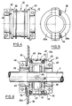
- FIG. 1 there is shown a plug 1 surrounding a telephone cable extending in a tube 3 for example buried.
- This plug 1 is fixed in leaktight manner at the end 4 having a circular opening of the tube 3.
- the plug 1 comprises a substantially cylindrical hollow body 5 constituted by two plastic shells 5a, 5b (see FIGS. 2 and 3) fixed around the cable 2 and comprising two jaws 6, 7 retained radially in grooves 8, 9 formed in said body and each comprising a central opening 10, 11 for passage of the cable 2. These central openings 10, 11 bear radially on the cable 2 during the fixing by tightening of the two shells 5a , 5b one on top of the other.
- the two jaws 6, 7 define between them a chamber 12 surrounding the cable 2 and filled with a sealing material which is injected into this chamber 12 through an opening 13 made in the wall of the body 5. Furthermore, the hollow body 5 is fixed in a removable and leaktight manner to the circular opening 4 for the passage of the cable 2 in the tube 3.
- the jaws 6 and 7 have been described in particular in French patent 2,582,854 of the applicant. They are made of plastic and have annular grooves which give them a radial elasticity which makes it possible to seal between the openings 10 and 11 of these jaws 6, 7 and the outer surface of the cable.
- the plug 1 further comprises a plastic sleeve 14 engaged in the end 4 of the tube 3 and whose outer diameter corresponds to the inner diameter of this tube 3.
- the sealed connection between the sleeve 14 and the internal surface of the tube 3 is provided by gluing.
- This sleeve 14 includes all around its end means for removably fixing it to the adjacent end of the hollow body 5.
- the sleeve 14 has for this purpose, at its end, a flange 15 and the hollow body 5 comprises at its adjacent end an annular groove 16 shaped to engage on the flange 15 of the sleeve 14. Furthermore, a seal 17 is provided between the annular groove 16 and the collar 15. In addition, the sleeve 14 comprises behind its collar 15 a second flange 18 which bears against the end 4 of the cable passage tube 3 2. The two flanges 15 and 18 define between them an annular space 19 in which is engaged the end edge 20 of the hollow body 5 adjacent to the annular groove 16.
- the sleeve 14 has inside a cover 21 (dotted line) which completely closes it off (when the tube 3 is not crossed by a cable), this cover 21 being connected to the internal face of the sleeve 14 by a frangible thinned annular zone 22 making it possible to remove this cover 21 to pass the cable 2 through the tube 3.
- the two shells 5a, 5b of the hollow body 5 comprise on each side two projecting parts 23a, 23b bearing on one another and each provided with an inclined ramp 24a, 24b relative to the contact plane P of the two projecting parts 23a, 23b.
- These ramps 24a, 24b are associated with an assembly member 25 of substantially C section comprising two counter-ramps 25a, 25b complementary to the ramps 24a, 24b of the two projecting parts and which can force-engage on the latter to tighten the two parts projecting one over the other.
- Figure 2 also shows that a seal is provided between the projecting portions 23a and 23b.
- the procedure is as follows. It will be assumed that the sleeve 14 is already in place at the end 4 of the tube. This sleeve 14 seals the end of the tube 3, which preserves the interior of the latter against humidity and dust. For put the cable 2 in the tube 3, just remove the cover 21 by pulling on the tab 21a to tear it off according to the circular area 22 adjacent to the internal surface of the sleeve 14, after which you can engage the cable 2 in tube 3.
- a sealing material is injected into the opening 13 of the plug, to fill the chamber 12 between the jaws 6, 7 and which surrounds the cable 2.
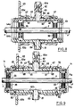
- FIGS. 4 and 5 show a plug 30 intended to be fixed as indicated in FIG. 6 in a nozzle 31 of circular section projecting from a wall 32.
- the plug 30 is of cylindrical shape and comprises two shells 33a, 33b (see FIG. 5) assembled one on the other by means of screws 34.
- the cylindrical hollow body defined by the two shells 33a, 33b comprises inside its two jaws 35, 36 identical to the jaws 6, 7 of the embodiment according to Figures 1 to 3 extending radially and bearing elastically on the cable 2.
- These jaws 35, 36 define between them a chamber 37 intended to be filled with a sealing material.
- the cylindrical hollow body 30 comprises on its external surface two annular grooves 38, 39 each receiving an O-ring 40, 41 sealing between the external surface of the hollow body 30 and the internal cylindrical surface 31a of the end piece 31.
- the hollow body 30 comprises near its end 42 a flange 43 bearing against the free end 31b of the end piece 31 and near its other end 44 an annular groove 45 receiving a key or elastic ring in the form of an arc of a circle 46 making it possible to removably lock the hollow body 30 against the inner face 32a of the wall 32.
- the external surface of the hollow body 30 comprises between the two grooves 38, 39 provided for receiving a seal 40, 41, an annular recess 47 which communicates through an orifice 48 with the internal chamber 37 between the two jaws 35, 36.
- the end piece 31 also has an orifice 49 for injecting a sealing material intended to fill the annular recess 47 and the chamber 37.
- the two shells 33a, 33b are fixed around the cable 2.
- the O-rings 40 and 41 are placed in the grooves 38, 39 provided on the outer surface of the plug 30. Then it suffices to slide the plug 30 into the end piece 31 until 'so that the flange 43 of the plug abuts against the free end 31b of the end piece 31.
- the plug 30 is then locked against the wall 32 by engaging the ring 46 in the groove 45.
- a sealant is injected into the opening 49 of the plug 30 which fills the recess 47 between the plug and the inner face of the end piece 31 as well as the chamber 37.
- the plug 30 can be removed from the end piece 31 to remove the cable and replace it with a new cable or one with a different diameter.
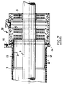
- the plug 50 differs from the version shown in FIG. 1.
- the sleeve 51 comprises on its outer surface engaged in the tube 3 for passage of the cable 2, a series of annular grooves 52. These grooves 52 have a longitudinal sawtooth section. These facilitate the bonding of the sleeve 51 in the tube 3.
- the sleeve 51 consists of two half-shells assembled along a plane passing through its axis.
- the sleeve 51 comprises, near the flange 54, an opening 55 for passage comprising a connector 56 allowing the screwing of a gas sampling valve (not shown). It is thus possible to detect the possible presence of gas in the tube 3 and to eliminate it by suction.
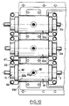
- the plugs 60, 61 are fixed in a nozzle 62 of circular section projecting from a wall 63 constituting the end wall of a sleeve for protecting the splice of one or multiple cables.
- the hollow body 64, 65 has a smooth exterior surface 66, the diameter of which corresponds to the interior diameter of the endpiece 62.
- the inner surface of the end piece 64, 65 comprises at least two annular grooves 67 of section rectangular each receiving a seal 68 of complementary section made of flexible material for sealing between the external surface 66 of the hollow body 64, 65 and the internal surface of the endpiece 62.
- the hollow body 64 is constituted by two half-shells 64a, 64b assembled along a plane passing through the axis XX 'of the hollow body. These two half-shells 64a, 64b are tightened one on the other by means of screws 69 placed at the two opposite ends of the hollow body 64.
- the hollow body 65 is constituted by a tubular body in one piece comprising near each of its ends an annular groove 70. These ends of the body 65 are each provided with a jaw holder 71 in two parts 71a, 71b assembled one against the other perpendicular to the axis XX ′ of the tubular body 65 by means of clamping screws 69.
- Each jaw holder 79 has on its edge adjacent to the tubular body 65 a groove 80 in an arc directed towards the axis X-X ′ of the body 65 and engaged in the annular groove 70 of this body.
- the two grooves 80 in an arc form a continuous circular groove when the two parts 71a, 71b of the jaw holder 70 are assembled one against the other, as shown in FIG. 9.
- the wall 63 is the end wall of a sleeve for protecting the splicing of electric cables 2.
- This sleeve comprises two half-shells 63a, 63b assembled one on the other along a plane passing through the 'axis XX ′ of the sleeve.
- Each end wall 63 of said sleeve comprises at least one endpiece 62 of circular section projecting towards the inside of the sleeve and receiving a plug 60 or 61.
- each tip 62 is in two parts 62a, 62b.
- Each end part 62, 62a is molded in one piece with the other end part and is assembled one on the other according to the assembly plane of the two half-shells 63a, 63b of the sleeve which passes through the axis XX ′.
- each plug 60, 61 has two diametrically opposite tubular protrusions 81, 82. Each of these protrusions is engaged in an opening 83, 84 made in the part 62a, 62b of the corresponding end piece.
- the two tubular protrusions 81, 82 consist respectively of a conduit 81 for injecting resin inside the hollow body 64, 65 and a conduit 82 in which is slidably mounted a piston 83a provided with a rod 84a which can project outside the duct to indicate the filling level of the resin.
- the half-shell 63b carries for this purpose three end pieces such as 62b in which are housed three plugs 61, 61a, 61b. These three plugs 61, 61a, 61b are trapped inside the sleeve after the upper half-shell (not shown in FIG. 10) has been placed on the lower half-shell 63b.
Landscapes
- Cable Accessories (AREA)
- Installation Of Indoor Wiring (AREA)
- Connector Housings Or Holding Contact Members (AREA)
- Insulating Bodies (AREA)
Claims (21)
- Verschluß, der es gestattet, ein Elektro- oder Telefonkabel (2) dicht in einem Rohr (3) oder Rohransatz (31, 62) kreisförmigen Querschnitts für den Durchgang des Kabels zu befestigen, wobei dieser Verschluß einen Hohlkörper (5, 30, 64, 65) enthält, der durch zwei Schalen (5a, 5b ; 33a, 33b ; 64a, 64b ; 71a, 71b) gebildet ist, die dazu bestimmt sind, um das Kabel (2) herum befestigt zu werden, und die wenigstens zwei Klemmbacken (6, 7; 35, 36) enthalten, die radial in dem Körper (5, 30, 64, 65) gehalten sind, jeweils eine mittlere Durchgangsöffnung (10, 11) für das Kabel (2) aufweisen und während der gegenseitigen Befestigung der beiden Schalen durch Zusammenpressen radial an diesem Kabel abgestützt sind, und wobei zwischen den beiden Klemmbacken eine Kammer (12, 37) gebildet ist, die dazu bestimmt ist, mit einem Dichtungsmaterial gefüllt zu werden, dadurch gekennzeichnet, daß der Hohlkörper (5) einen Teil (14, 51) aufweist, der dicht, oder der Hohlkörper (30, 64, 65) dicht, in das Innere des Rohres (3) oder Rohransatzes (31, 62) einsetzbar ist, wobei das Teil (14, 51) einen Flansch (18, 54) aufweist, oder der Hohlkörper (30, 64, 65) einen Flansch (43) beziehungsweise rohrförmigen Vorsprünge (81, 82) aufweist, die dazu vorgesehen ist oder sind, an dem Rohr (3) oder Rohransatz (31, 62) in Anlage zu kommen, und daß abnehmbare Mittel vorgesehen sind, um den Hohlkörper (5, 30, 64, 65) hinsichtlich des Rohres (3) oder Rohransatzes (31, 62) axial festzuhalten.
- Verschluß nach Anspruch 1, der dazu bestimmt ist, an dem Ende (4) eines Durchgangsrohres (3) für das Kabel (2) befestigt zu werden, dadurch gekennzeichnet, daß er überdies eine Muffe (14) enthält, die dazu bestimmt ist, in das Ende (4) des Rohres eingeführt zu werden und deren Außendurchmesser dem Innendurchmesser des Rohres entspricht, wobei diese Muffe um den ganzen Umfang eines ihrer Enden herum Mittel aufweist, um ein Ende (20) des Hohlkörpers (5) an der Muffe (14) abnehmbar zu befestigen.
- Verschluß nach Anspruch 2, dadurch gekennzeichnet, daß die Muffe (14) an ihrem Ende einen Kragen (15) aufweist und daß der Hohlkörper (5) an seinem angrenzenden Ende eine Ringnut (16) besitzt, die auf den Kragen (15) der Muffe (14) aufsetzbar ist.
- Verschluß nach Anspruch 3, dadurch gekennzeichnet, daß zwischen der Ringnut (16) und dem Kragen (15) eine Dichtung (17) vorgesehen ist.
- Verschluß nach einem der Ansprüche 3 oder 4, dadurch gekennzeichnet, daß die Muffe (14) hinter ihrem Kragen (15) einen zweiten Kragen (18) besitzt, der dazu bestimmt ist, sich an dem Ende (4) des Durchgangsrohres (3) für das Kabel (2) abzustützen, wobei zwischen den beiden Krägen (15, 18) ein Ringraum (19) gebildet ist, der den an die Ringnut (16) angrenzenden Endrand (20) des Hohlkörpers (5) aufnimmt.
- Verschluß nach einem der Ansprüche 2 bis 5, dadurch gekennzeichnet, daß die Muffe (14) in ihrem Inneren einen Dekkel (21) enthält, der sie vollständig verschließt, wobei dieser Deckel (21) mit der Innenseite der Muffe (14) über eine geschwächte und abbrechbare Ringzone (22) verbunden ist, die es gestattet, diesen Deckel (21) herauszureißen, um das Kabel (2) hindurchzuführen.
- Verschluß nach einem der Ansprüche 1 bis 6, dadurch gekennzeichnet, daß die beiden Schalen (5a, 5b) des Hohlkörpers auf jeder Seite zwei vorspringende Teile (23a, 23b) aufweisen, die dazu bestimmt sind, in gegenseitige Anlage zu treten, und die jeweils mit einer Rampe (24a, 24b) versehen sind, die bezüglich der Berührungsebene (P) der beiden vorspringenden Teile (23a, 23b) geneigt ist, wobei diesen letzteren ein im Querschnitt im wesentlichen C-förmiges Montageelement (25) zugeordnet ist, das zwei Gegenrampen (25a, 25b) besitzt, die zu den Rampen (24a, 24b) der beiden vorspringenden Teile (23a, 23b) komplementär sind, und das unter Aufbringung einer Kraft auf diese letzteren aufsetzbar ist, um die beiden vorspringenden Teile gegeneinander zu drücken.
- Verschluß nach Anspruch 1, der dazu bestimmt ist, in einem Ansatz (31) kreisförmigen Querschnitts befestigt zu werden, der von einer Wand (32) vorspringt, dadurch gekennzeichnet, daß der Hohlkörper (30) an seiner Außenfläche wenigstens zwei Ringnuten (38, 39) aufweist, die jeweils eine Ringdichtung (40, 41) aufnehmen, die dazu bestimmt ist, die Abdichtung zwischen der Außenfläche des Hohlkörpers (30) und der Innenfläche des Ansatzes (31) zu bewirken.
- Verschluß nach Anspruch 8, dadurch gekennzeichnet, daß der Hohlkörper (31) in der Nähe des einen seiner Enden einen Kragen (43) aufweist, der dazu bestimmt ist, sich an dem freien Ende des Ansatzes (31) abzustützen, und in der Nähe seines anderen Endes eine Ringnut (45) besitzt, die dazu bestimmt ist, einen Keil (46) in Form eines Kreisbogens aufzunehmen, der dazu vorgesehen ist, den Hohlkörper (30) in lösbarer Weise gegenüber der Innenseite der Wand (32) zu verriegeln.
- Verschluß nach einem der Ansprüche 8 oder 9, dadurch gekennzeichnet, daß die Außenfläche des Hohlkörpers zwischen den beiden Nuten (38, 39), die zur Aufnahme einer Ringdichtung vorgesehen sind, eine ringförmige Ausnehmung (47) besitzt, die über eine Öffnung (48) mit der inneren Kammer (37) in Verbindung steht, die zwischen den beiden Klemmbacken (35, 36) liegt, wobei der Ansatz (31) eine Öffnung (49) zum Einspritzen eines Dichtungsmaterials enthält, das dazu bestimmt ist, die ringförmige Ausnehmung (47) und die Kammer (37) zu füllen.
- Verschluß nach einem der Ansprüche 1 bis 7, dadurch gekennzeichnet, daß die Muffe (51) an ihrer Außenfläche, die dazu bestimmt ist, in das Durchgangsrohr (3) für das Kabel (2) eingesetzt zu werden, eine Reihe von Ringnuten (52) aufweist.
- Verschluß nach Anspruch 11, dadurch gekennzeichnet, daß die Nuten (52) im Längsschnitt eine Sägezahnform aufweisen.
- Verschluß nach einem der Ansprüche 11 oder 12, dadurch gekennzeichnet, daß die Muffe (51) durch zwei Halbschaben gebildet ist, die in einer durch ihre Achse verlaufenden Ebene zusammengesetzt sind.
- Verschluß nach einem der Ansprüche 11 bis 13, dadurch gekennzeichnet, daß die Muffe (51) in der Nähe des Flansches (54) eine Durchgangsöffnung (55) aufweist, die das Einschrauben eines Gasentnahmeventils gestattet.
- Verschluß nach Anspruch 1, wobei dieser Verschluß (60, 61) dazu bestimmt ist, in einem Ansatz (62) kreisförmigen Querschnitts befestigt zu werden, der von einer Wand (63) vorspringt, die die Endwand einer Schutzmuffe zum Schutz der Spleißstelle eines oder mehrer Kabel bilden kann, dadurch gekennzeichnet, daß der Hohlkörper (64, 65) eine glatte Außenfläche (66) aufweist, deren Durchmesser dem Innendurchmesser des Ansatzes (62) entspricht, und daß die Innenfläche des Ansatzes zumindest zwei Ringnuten (67) rechteckigen Querschnitts enthält, die jeweils eine Dichtung (68) komplementären Querschnitts aus nachgiebigem Material aufnehmen, um die Abdichtung zwischen der Außenfläche (66) des Hohlkörper (64, 65) und der Innenfläche des Ansatzes (62) zu bewirken.
- Verschluß nach Anspruch 15, dadurch gekennzeichnet, daß der Hohlkörper (64) durch zwei Halbschalen (64a, 64b) gebildet ist, die in einer durch die Achse (X-X′) des Hohlkörpers verlaufenden Ebene zusammengesetzt sind, wobei diese beiden Halbschalen (64a, 64b) mittels Schrauben (69) gegeneinandergepreßt sind, die an den beiden entgegengesetzten Enden des Hohlkörpers (64) vorgesehen sind.
- Verschluß nach Anspruch 15, dadurch gekennzeichnet, daß der Hohlkörper (65) durch einen einteiligen Rohrkörper gebildet ist, der in der Nähe seiner Enden jeweils eine Ringnut (70) besitzt, wobei diese Enden jeweils mit einem Klemmbakkenträger (71) aus zwei Teilen (71a, 71b) versehen sind, die senkrecht zu der Achse (X-X′) des Rohrkörpers (65) mittels Klemmschrauben (69) aneinandergesetzt sind, jeder Klemmbakkenträger (71) an seinem an den Rohrkörper (65) angrenzenden Rand eine kreisbogenförmige Nut (80) aufweist, die zu der Achse (X-X′) des Körpers hin gerichtet ist und in die Ringnut (70) dieses Körpers eingreift, und die beiden kreisbogenförmigen Nuten (80) eine kontinuierliche kreisförmige Nut bilden, wenn die beiden Teile (71a, 71b) des Klemmbackenträgers (70) aneinandergesetzt sind.
- Muffe zum Schützen der Spleißstelle von Elektrokabeln (2, 2a, 2b) mit zwei Halbschalen (63a, 63b), die in einer durch die Achse (X-X′) der Muffe verlaufenden Ebene aneinandergesetzt sind, wobei jedes Ende der Muffe wenigstens einen Ansatz (62) kreisförmigen Querschnitts aufweist, der in das Innere der Muffe vorsteht und einen Verschluß (60, 61) entsprechend einem der Ansprüche 15 bis 17 aufnimmt.
- Muffe nach Anspruch 18, dadurch gekennzeichnet, daß jeder Ansatz (62) aus zwei Teilen (62a, 62b) besteht, wobei jeder Ansatzteil aus einem Stück mit dem anderen Ansatzteil gegossen ist und die Ansatzteile in der Montageebene der beiden Halbschalen (63a, 63b) der Muffe aneinandergesetzt werden.
- Muffe nach Anspruch 19, dadurch gekennzeichnet, daß der Hohlkörper (64, 65) eines jeden Verschlusses (60, 61) zwei diametral entgegengesetzte rohrförmige Vorsprünge (81, 82) aufweist, wobei jeder dieser Vorsprünge in eine Öffnung (83, 84) eingesetzt ist, die in dem entsprechenden Teil des Ansatzes ausgebildet ist.
- Muffe nach Anspruch 20, dadurch gekennzeichnet, daß die beiden rohrförmigen Vorsprünge (81, 82) durch eine Einspritzleitung zum Einspritzen von Harz in das Innere des Hohlkörpers bzw. eine Leitung gebildet sind, in der ein Kolben (83a) verschiebbar angeordnet ist, der mit einer Stange (84a) versehen ist, die aus der Leitung heraustreten kann, um den Füllstand des Harzes anzuzeigen.
Priority Applications (18)
| Application Number | Priority Date | Filing Date | Title |
|---|---|---|---|
| FR9000798A FR2657473B1 (fr) | 1990-01-24 | 1990-01-24 | Bouchon pour fixer de facon etanche un cable electrique a une ouverture. |
| EP91400364A EP0499754B1 (de) | 1990-01-24 | 1991-02-13 | Verschluss zum dichten Befestigen eines elektrischen Kabels in einer Öffnung und Kabelschutzmuffe mit solchen Verschlüssen |
| AT91400364T ATE130974T1 (de) | 1990-01-24 | 1991-02-13 | Verschluss zum dichten befestigen eines elektrischen kabels in einer öffnung und kabelschutzmuffe mit solchen verschlüssen. |
| DE199191400364T DE499754T1 (de) | 1990-01-24 | 1991-02-13 | Verschluss zum dichten befestigen eines elektrischen kabels in einer oeffnung und kabelschutzmuffe mit solchen verschluessen. |
| ES91400364T ES2035816T3 (es) | 1990-01-24 | 1991-02-13 | Tapon para fijar de forma estanca un cable electrico a una abertura y manguito de proteccion de cables que comprende tales tapones. |
| DK91400364.5T DK0499754T3 (da) | 1990-01-24 | 1991-02-13 | Dåse til tætnende fastgørelse af et elektrisk kabel i en åbning og beskyttelsesmuffe for kablet knyttet til sådanne dåser |
| DE69115019T DE69115019T2 (de) | 1990-01-24 | 1991-02-13 | Verschluss zum dichten Befestigen eines elektrischen Kabels in einer Öffnung und Kabelschutzmuffe mit solchen Verschlüssen. |
| MC91@@D MC2292A1 (fr) | 1990-01-24 | 1991-02-20 | Bouchon pour fixer de facon etanche un cable electrique a une ouverture etmanchon de protection de cable comportant de tels bouchons |
| AU74583/91A AU654273B2 (en) | 1990-01-24 | 1991-02-20 | Plug for sealingly securing an electric cable in an opening and cable protection sleeve comprising a number of said plugs |
| US07/938,138 US5302779A (en) | 1990-01-24 | 1991-02-20 | Plug for fixing in an impermeable manner an electric cable to an opening and cable protection sleeve comprising such plugs |
| PCT/FR1991/000135 WO1992015138A1 (fr) | 1990-01-24 | 1991-02-20 | Bouchon pour fixer de façon etanche un cable electrique a une ouverture et manchon de protection de cables comportant de tels bouchons |
| BR9106413A BR9106413A (pt) | 1990-01-24 | 1991-02-20 | Bujão para fixar, de forma estanque, um cabo elétrico a uma abertura, e luva de proteção de cabos, comportando esses bujões |
| JP91505404A JPH05505506A (ja) | 1990-01-24 | 1991-02-20 | 電気ケーブルを開口部に密封状に固定するためのプラグ及びそのようなプラグを備えたケーブル保護スリーブ |
| IL9736191A IL97361A (en) | 1990-01-24 | 1991-02-26 | Plug for fixing in an impermeable manner an electric cable to an opening and cable protection sleeve comprising such plugs |
| PT96907A PT96907A (pt) | 1990-01-24 | 1991-02-27 | Tampao para fixar de maneira estanque um cabo electrico numa abertura e manga de proteccao de cabos que inclui tais tampoes |
| CN91101916A CN1025395C (zh) | 1990-01-24 | 1991-02-27 | 将电缆密封固定在管状部分的插塞 |
| OA60290A OA09797A (fr) | 1990-01-24 | 1992-10-20 | "Bouchon pour fixer de façon étanche un cable électrique à une ouverture et manchon de protection de cables comportant de tels bouchons". |
| GR930300006T GR930300006T1 (en) | 1990-01-24 | 1993-04-28 | Closure for securely fixing an electrical cable to an opening and protective cable sleeve comprising such closures. |
Applications Claiming Priority (8)
| Application Number | Priority Date | Filing Date | Title |
|---|---|---|---|
| FR9000798A FR2657473B1 (fr) | 1990-01-24 | 1990-01-24 | Bouchon pour fixer de facon etanche un cable electrique a une ouverture. |
| EP91400364A EP0499754B1 (de) | 1990-01-24 | 1991-02-13 | Verschluss zum dichten Befestigen eines elektrischen Kabels in einer Öffnung und Kabelschutzmuffe mit solchen Verschlüssen |
| AU74583/91A AU654273B2 (en) | 1990-01-24 | 1991-02-20 | Plug for sealingly securing an electric cable in an opening and cable protection sleeve comprising a number of said plugs |
| PCT/FR1991/000135 WO1992015138A1 (fr) | 1990-01-24 | 1991-02-20 | Bouchon pour fixer de façon etanche un cable electrique a une ouverture et manchon de protection de cables comportant de tels bouchons |
| IL9736191A IL97361A (en) | 1990-01-24 | 1991-02-26 | Plug for fixing in an impermeable manner an electric cable to an opening and cable protection sleeve comprising such plugs |
| CN91101916A CN1025395C (zh) | 1990-01-24 | 1991-02-27 | 将电缆密封固定在管状部分的插塞 |
| PT96907A PT96907A (pt) | 1990-01-24 | 1991-02-27 | Tampao para fixar de maneira estanque um cabo electrico numa abertura e manga de proteccao de cabos que inclui tais tampoes |
| OA60290A OA09797A (fr) | 1990-01-24 | 1992-10-20 | "Bouchon pour fixer de façon étanche un cable électrique à une ouverture et manchon de protection de cables comportant de tels bouchons". |
Publications (2)
| Publication Number | Publication Date |
|---|---|
| EP0499754A1 EP0499754A1 (de) | 1992-08-26 |
| EP0499754B1 true EP0499754B1 (de) | 1995-11-29 |
Family
ID=33163306
Family Applications (1)
| Application Number | Title | Priority Date | Filing Date |
|---|---|---|---|
| EP91400364A Expired - Lifetime EP0499754B1 (de) | 1990-01-24 | 1991-02-13 | Verschluss zum dichten Befestigen eines elektrischen Kabels in einer Öffnung und Kabelschutzmuffe mit solchen Verschlüssen |
Country Status (14)
| Country | Link |
|---|---|
| EP (1) | EP0499754B1 (de) |
| JP (1) | JPH05505506A (de) |
| CN (1) | CN1025395C (de) |
| AT (1) | ATE130974T1 (de) |
| DE (2) | DE69115019T2 (de) |
| DK (1) | DK0499754T3 (de) |
| ES (1) | ES2035816T3 (de) |
| FR (1) | FR2657473B1 (de) |
| GR (1) | GR930300006T1 (de) |
| IL (1) | IL97361A (de) |
| MC (1) | MC2292A1 (de) |
| OA (1) | OA09797A (de) |
| PT (1) | PT96907A (de) |
| WO (1) | WO1992015138A1 (de) |
Families Citing this family (13)
| Publication number | Priority date | Publication date | Assignee | Title |
|---|---|---|---|---|
| DE9303790U1 (de) * | 1993-03-15 | 1994-07-21 | Walter Rose Gmbh & Co Kg, 58093 Hagen | Bausatz zur Erzeugung einer Fernmelde-Kabelmuffe |
| GB9805965D0 (en) * | 1998-03-21 | 1998-05-20 | Cannon Telecomms Limited | Single-ended joint cable sealing system |
| US6852922B2 (en) | 2001-07-13 | 2005-02-08 | Houston Wire & Cable Company | Apparatus and method for sealing a conduit |
| CN103107504A (zh) * | 2011-11-15 | 2013-05-15 | 河南省电力公司安阳供电公司 | 塑胶电缆管的封堵方法及其塑胶电缆管 |
| JP5962960B2 (ja) * | 2012-03-01 | 2016-08-03 | 株式会社ジェイテクト | 電子ユニットの防水構造 |
| CN103078288B (zh) * | 2013-01-04 | 2015-06-24 | 衢州市易凡设计有限公司 | 连接电缆抗拉伸防水绝缘套管 |
| CN103683163A (zh) * | 2013-11-20 | 2014-03-26 | 北京四方如钢混凝土制品有限公司 | 一种管道单元和电缆管道 |
| CN106159830A (zh) * | 2016-06-24 | 2016-11-23 | 苏州华本机电有限公司 | 一种带锁止功能的线缆组件 |
| CN107591771B (zh) * | 2017-11-03 | 2023-08-22 | 苏州热工研究院有限公司 | 一种电缆密封装置 |
| CN107732694B (zh) * | 2017-11-30 | 2023-07-21 | 安徽广祺智能电器股份有限公司 | 一种防凝露环网柜及其制作方法与配电系统 |
| CN109273175A (zh) * | 2018-11-08 | 2019-01-25 | 合肥恒大江海泵业股份有限公司 | 一种电缆注胶烘干装置 |
| CN111540526B (zh) * | 2020-04-30 | 2021-12-21 | 安徽电缆股份有限公司 | 一种石油平台专用耐油性电缆 |
| CN114927284A (zh) * | 2022-05-23 | 2022-08-19 | 南京金龙特种汽车有限公司 | 一种基于格兰头的双芯高压线的制作设备及其制作方法 |
Citations (4)
| Publication number | Priority date | Publication date | Assignee | Title |
|---|---|---|---|---|
| DE2826584A1 (de) * | 1978-06-16 | 1979-12-20 | Siemens Ag | Dichtungskoerper zur einfuehrung von doppelmantelkabeln in kabelgarnituren |
| EP0098765A1 (de) * | 1982-06-30 | 1984-01-18 | ETABLISSEMENTS MOREL - ATELIERS ELECTROMECANIQUES DE FAVIERES (Société Anonyme) | Muffe zum Schutz eines Spleisses von elektrischen oder Nachrichtenkabeln |
| EP0206854A1 (de) * | 1985-05-31 | 1986-12-30 | ETABLISSEMENTS MOREL - ATELIERS ELECTROMECANIQUES DE FAVIERES (Société Anonyme) | Verfahren zum Schutz von Kabelspleissen und Muffe zur Ausführung dieses Vefahrens |
| GB2193605A (en) * | 1986-07-11 | 1988-02-10 | British Telecomm | Reusable cable joint cover |
Family Cites Families (7)
| Publication number | Priority date | Publication date | Assignee | Title |
|---|---|---|---|---|
| DE419820C (de) * | 1925-10-12 | Felten & Guilleaume Carlswerk | Verbindungsmuffe fuer Hochspannungskabel | |
| US4262167A (en) * | 1979-07-18 | 1981-04-14 | Minnesota Mining And Manufacturing Company | Cable splice case |
| FR2466887A1 (fr) * | 1979-08-09 | 1981-04-10 | Morel Atel Electromec | Bouchon d'etancheite pour canalisation de cable electrique et procede s'y rapportant |
| DE3274170D1 (en) * | 1981-08-20 | 1986-12-11 | Felten & Guilleaume Ag Oester | Longitudinally split pressure-resistant cable sleeve |
| FR2596215B1 (fr) * | 1986-03-24 | 1990-12-21 | Kerboul Michel | Dispositif de protection d'epissure de cables |
| DE3710755A1 (de) * | 1986-05-15 | 1988-10-13 | Rose Walter Gmbh & Co Kg | Vorrichtung, insbesondere zum abdichten von schachtwaenden und kabelkanalzuegen |
| US4704499A (en) * | 1986-06-18 | 1987-11-03 | American Telephone And Telegraph Company At&T Bell Laboratories | Locking mechanism for aerial cable closure and terminals |
-
1990
- 1990-01-24 FR FR9000798A patent/FR2657473B1/fr not_active Expired - Lifetime
-
1991
- 1991-02-13 DE DE69115019T patent/DE69115019T2/de not_active Expired - Fee Related
- 1991-02-13 EP EP91400364A patent/EP0499754B1/de not_active Expired - Lifetime
- 1991-02-13 DK DK91400364.5T patent/DK0499754T3/da active
- 1991-02-13 ES ES91400364T patent/ES2035816T3/es not_active Expired - Lifetime
- 1991-02-13 DE DE199191400364T patent/DE499754T1/de active Pending
- 1991-02-13 AT AT91400364T patent/ATE130974T1/de not_active IP Right Cessation
- 1991-02-20 MC MC91@@D patent/MC2292A1/xx unknown
- 1991-02-20 WO PCT/FR1991/000135 patent/WO1992015138A1/fr not_active Ceased
- 1991-02-20 JP JP91505404A patent/JPH05505506A/ja active Pending
- 1991-02-26 IL IL9736191A patent/IL97361A/en not_active IP Right Cessation
- 1991-02-27 PT PT96907A patent/PT96907A/pt not_active Application Discontinuation
- 1991-02-27 CN CN91101916A patent/CN1025395C/zh not_active Expired - Fee Related
-
1992
- 1992-10-20 OA OA60290A patent/OA09797A/fr unknown
-
1993
- 1993-04-28 GR GR930300006T patent/GR930300006T1/el unknown
Patent Citations (4)
| Publication number | Priority date | Publication date | Assignee | Title |
|---|---|---|---|---|
| DE2826584A1 (de) * | 1978-06-16 | 1979-12-20 | Siemens Ag | Dichtungskoerper zur einfuehrung von doppelmantelkabeln in kabelgarnituren |
| EP0098765A1 (de) * | 1982-06-30 | 1984-01-18 | ETABLISSEMENTS MOREL - ATELIERS ELECTROMECANIQUES DE FAVIERES (Société Anonyme) | Muffe zum Schutz eines Spleisses von elektrischen oder Nachrichtenkabeln |
| EP0206854A1 (de) * | 1985-05-31 | 1986-12-30 | ETABLISSEMENTS MOREL - ATELIERS ELECTROMECANIQUES DE FAVIERES (Société Anonyme) | Verfahren zum Schutz von Kabelspleissen und Muffe zur Ausführung dieses Vefahrens |
| GB2193605A (en) * | 1986-07-11 | 1988-02-10 | British Telecomm | Reusable cable joint cover |
Also Published As
| Publication number | Publication date |
|---|---|
| FR2657473A1 (fr) | 1991-07-26 |
| CN1025395C (zh) | 1994-07-06 |
| MC2292A1 (fr) | 1993-07-14 |
| JPH05505506A (ja) | 1993-08-12 |
| DK0499754T3 (da) | 1996-04-09 |
| DE499754T1 (de) | 1993-05-19 |
| OA09797A (fr) | 1994-04-15 |
| DE69115019T2 (de) | 1996-07-11 |
| DE69115019D1 (de) | 1996-01-11 |
| PT96907A (pt) | 1993-02-26 |
| GR930300006T1 (en) | 1993-04-28 |
| ATE130974T1 (de) | 1995-12-15 |
| CN1064570A (zh) | 1992-09-16 |
| EP0499754A1 (de) | 1992-08-26 |
| FR2657473B1 (fr) | 1992-03-27 |
| IL97361A (en) | 1994-08-26 |
| ES2035816T3 (es) | 1996-03-16 |
| WO1992015138A1 (fr) | 1992-09-03 |
| ES2035816T1 (es) | 1993-05-01 |
Similar Documents
| Publication | Publication Date | Title |
|---|---|---|
| EP0913613B1 (de) | Manschette für ein Rohrelement | |
| EP0039703B1 (de) | Muffe zum schutz des spleisses elektrischer oder telefonischer kabel | |
| EP0499754A1 (de) | Verschluss zum dichten Befestigen eines elektrischen Kabels in einer Öffnung und Kabelschutzmuffe mit solchen Verschlüssen | |
| EP0469949A1 (de) | Vorrichtung zur schnellen Verbindung eines Schlauches mit einem Automobilwärmetauscher | |
| FR2626660A1 (fr) | Dispositif d'assemblage pour un ensemble echangeur de chaleur/raccord tubulaire | |
| FR2710717A1 (fr) | Connexion rapide pour emmanchement d'un tube rigide dans un embout. | |
| CA2321137A1 (fr) | Dispositif de connexion d'une extremite de conduite a un organe | |
| EP1273843A1 (de) | Wiederverwendbare Kupplung zum Verbinden von verstärkten Schlauchenden | |
| FR2715454A1 (fr) | Connexion rapide. | |
| FR2669710A1 (fr) | Accouplement pour flexible, muni d'une piece tubulaire d'accouplement. | |
| EP1321241A1 (de) | Druckgaspatrone für Befestigungsgerät und Adapter für Verbindungsmuffe | |
| FR2737275A1 (fr) | Raccord de tuyaux antiseparation | |
| FR2679313A1 (fr) | Dispositif de serrage etanche pour le serrage d'un tube flexible monte a force a l'interieur d'un raccord tubulaire. | |
| EP0989348B1 (de) | Vorrichtung zum Schnellverbinden von Rohren | |
| FR2528533A1 (fr) | Raccord traversant a ecrou tournant pour gaine exterieurement spiralee | |
| EP0833093A1 (de) | Vorrichtung zur dichten Stosskupplung von zwei Rohren aus Metall | |
| FR3042579A1 (fr) | Dispositif de visualisation de sertissage pour un raccord a sertir | |
| FR2687757A1 (fr) | Accouplement emboitable pour relier des conduits parcourus par un fluide. | |
| FR2982039A1 (fr) | Raccord pour circuit de fibres optiques et procede de connexion d'un tel circuit a un tel raccord | |
| EP0327441B1 (de) | Wärmetauscher | |
| EP0595742A1 (de) | Vorrichtung zum Verbinden von Wellrohrabschnitten aus Kunststoff | |
| FR2710790A1 (fr) | Dispositif de traversée étanche. | |
| FR2631750A1 (fr) | Douille de lampe en matiere synthetique, fixable dans une ouverture de montage d'un feu d'automobile | |
| EP0882926B1 (de) | Einen gewellten Schlauch und eine Schnellverbindung aufweisende Anordnung | |
| FR2653654A1 (fr) | Boitier a raccord tournant pour suceur d'aspirateur. |
Legal Events
| Date | Code | Title | Description |
|---|---|---|---|
| PUAI | Public reference made under article 153(3) epc to a published international application that has entered the european phase |
Free format text: ORIGINAL CODE: 0009012 |
|
| 17P | Request for examination filed |
Effective date: 19910218 |
|
| AK | Designated contracting states |
Kind code of ref document: A1 Designated state(s): AT BE CH DE DK ES FR GB GR IT LI LU NL SE |
|
| ITCL | It: translation for ep claims filed |
Representative=s name: BARZANO' E ZANARDO ROMA S.P.A. |
|
| TCNL | Nl: translation of patent claims filed | ||
| GBC | Gb: translation of claims filed (gb section 78(7)/1977) | ||
| DET | De: translation of patent claims | ||
| 17Q | First examination report despatched |
Effective date: 19940711 |
|
| GRAA | (expected) grant |
Free format text: ORIGINAL CODE: 0009210 |
|
| AK | Designated contracting states |
Kind code of ref document: B1 Designated state(s): AT BE CH DE DK ES FR GB GR IT LI LU NL SE |
|
| PG25 | Lapsed in a contracting state [announced via postgrant information from national office to epo] |
Ref country code: NL Free format text: LAPSE BECAUSE OF FAILURE TO SUBMIT A TRANSLATION OF THE DESCRIPTION OR TO PAY THE FEE WITHIN THE PRESCRIBED TIME-LIMIT Effective date: 19951129 Ref country code: GR Free format text: LAPSE BECAUSE OF FAILURE TO SUBMIT A TRANSLATION OF THE DESCRIPTION OR TO PAY THE FEE WITHIN THE PRESCRIBED TIME-LIMIT Effective date: 19951129 |
|
| REF | Corresponds to: |
Ref document number: 130974 Country of ref document: AT Date of ref document: 19951215 Kind code of ref document: T |
|
| ITF | It: translation for a ep patent filed | ||
| REF | Corresponds to: |
Ref document number: 69115019 Country of ref document: DE Date of ref document: 19960111 |
|
| PGFP | Annual fee paid to national office [announced via postgrant information from national office to epo] |
Ref country code: GB Payment date: 19960205 Year of fee payment: 6 |
|
| PG25 | Lapsed in a contracting state [announced via postgrant information from national office to epo] |
Ref country code: AT Effective date: 19960213 |
|
| REG | Reference to a national code |
Ref country code: CH Ref legal event code: NV Representative=s name: IPTO S.A. |
|
| PGFP | Annual fee paid to national office [announced via postgrant information from national office to epo] |
Ref country code: ES Payment date: 19960216 Year of fee payment: 6 |
|
| PG25 | Lapsed in a contracting state [announced via postgrant information from national office to epo] |
Ref country code: LI Free format text: LAPSE BECAUSE OF NON-PAYMENT OF DUE FEES Effective date: 19960228 Ref country code: DK Effective date: 19960228 Ref country code: CH Free format text: LAPSE BECAUSE OF NON-PAYMENT OF DUE FEES Effective date: 19960228 Ref country code: BE Effective date: 19960228 |
|
| PGFP | Annual fee paid to national office [announced via postgrant information from national office to epo] |
Ref country code: FR Payment date: 19960228 Year of fee payment: 6 |
|
| REG | Reference to a national code |
Ref country code: DK Ref legal event code: EBP |
|
| PG25 | Lapsed in a contracting state [announced via postgrant information from national office to epo] |
Ref country code: SE Effective date: 19960229 Ref country code: LU Free format text: LAPSE BECAUSE OF NON-PAYMENT OF DUE FEES Effective date: 19960229 |
|
| REG | Reference to a national code |
Ref country code: ES Ref legal event code: FG2A Ref document number: 2035816 Country of ref document: ES Kind code of ref document: T3 |
|
| GBT | Gb: translation of ep patent filed (gb section 77(6)(a)/1977) |
Effective date: 19960301 |
|
| REG | Reference to a national code |
Ref country code: DK Ref legal event code: T3 |
|
| PGFP | Annual fee paid to national office [announced via postgrant information from national office to epo] |
Ref country code: DE Payment date: 19960424 Year of fee payment: 6 |
|
| NLV1 | Nl: lapsed or annulled due to failure to fulfill the requirements of art. 29p and 29m of the patents act | ||
| BERE | Be: lapsed |
Owner name: ETS MOREL - ATELIERS ELECTROMECANIQUES DE FAVIERE Effective date: 19960228 |
|
| PLBE | No opposition filed within time limit |
Free format text: ORIGINAL CODE: 0009261 |
|
| STAA | Information on the status of an ep patent application or granted ep patent |
Free format text: STATUS: NO OPPOSITION FILED WITHIN TIME LIMIT |
|
| REG | Reference to a national code |
Ref country code: CH Ref legal event code: PL |
|
| 26N | No opposition filed | ||
| PG25 | Lapsed in a contracting state [announced via postgrant information from national office to epo] |
Ref country code: GB Effective date: 19970213 |
|
| PG25 | Lapsed in a contracting state [announced via postgrant information from national office to epo] |
Ref country code: ES Free format text: LAPSE BECAUSE OF NON-PAYMENT OF DUE FEES Effective date: 19970214 |
|
| GBPC | Gb: european patent ceased through non-payment of renewal fee |
Effective date: 19970213 |
|
| PG25 | Lapsed in a contracting state [announced via postgrant information from national office to epo] |
Ref country code: FR Effective date: 19971030 |
|
| PG25 | Lapsed in a contracting state [announced via postgrant information from national office to epo] |
Ref country code: DE Effective date: 19971101 |
|
| REG | Reference to a national code |
Ref country code: FR Ref legal event code: ST |
|
| REG | Reference to a national code |
Ref country code: ES Ref legal event code: FD2A Effective date: 19990301 |
|
| PG25 | Lapsed in a contracting state [announced via postgrant information from national office to epo] |
Ref country code: IT Free format text: LAPSE BECAUSE OF NON-PAYMENT OF DUE FEES Effective date: 20050213 |