EP0499997A1 - Dispositif de mesure de position avec un appareil de l'ajustement - Google Patents
Dispositif de mesure de position avec un appareil de l'ajustement Download PDFInfo
- Publication number
- EP0499997A1 EP0499997A1 EP92102565A EP92102565A EP0499997A1 EP 0499997 A1 EP0499997 A1 EP 0499997A1 EP 92102565 A EP92102565 A EP 92102565A EP 92102565 A EP92102565 A EP 92102565A EP 0499997 A1 EP0499997 A1 EP 0499997A1
- Authority
- EP
- European Patent Office
- Prior art keywords
- measuring
- graduation
- measuring device
- scanning unit
- sensitive photodetector
- Prior art date
- Legal status (The legal status is an assumption and is not a legal conclusion. Google has not performed a legal analysis and makes no representation as to the accuracy of the status listed.)
- Granted
Links
- 238000005259 measurement Methods 0.000 abstract description 5
- 230000001419 dependent effect Effects 0.000 description 7
- 230000002452 interceptive effect Effects 0.000 description 3
- 238000000034 method Methods 0.000 description 2
- 230000003287 optical effect Effects 0.000 description 2
- 238000011161 development Methods 0.000 description 1
- 230000018109 developmental process Effects 0.000 description 1
- 230000010363 phase shift Effects 0.000 description 1
- BASFCYQUMIYNBI-UHFFFAOYSA-N platinum Chemical compound [Pt] BASFCYQUMIYNBI-UHFFFAOYSA-N 0.000 description 1
Images


Classifications
-
- G—PHYSICS
- G01—MEASURING; TESTING
- G01D—MEASURING NOT SPECIALLY ADAPTED FOR A SPECIFIC VARIABLE; ARRANGEMENTS FOR MEASURING TWO OR MORE VARIABLES NOT COVERED IN A SINGLE OTHER SUBCLASS; TARIFF METERING APPARATUS; MEASURING OR TESTING NOT OTHERWISE PROVIDED FOR
- G01D5/00—Mechanical means for transferring the output of a sensing member; Means for converting the output of a sensing member to another variable where the form or nature of the sensing member does not constrain the means for converting; Transducers not specially adapted for a specific variable
- G01D5/26—Mechanical means for transferring the output of a sensing member; Means for converting the output of a sensing member to another variable where the form or nature of the sensing member does not constrain the means for converting; Transducers not specially adapted for a specific variable characterised by optical transfer means, i.e. using infrared, visible, or ultraviolet light
- G01D5/32—Mechanical means for transferring the output of a sensing member; Means for converting the output of a sensing member to another variable where the form or nature of the sensing member does not constrain the means for converting; Transducers not specially adapted for a specific variable characterised by optical transfer means, i.e. using infrared, visible, or ultraviolet light with attenuation or whole or partial obturation of beams of light
- G01D5/34—Mechanical means for transferring the output of a sensing member; Means for converting the output of a sensing member to another variable where the form or nature of the sensing member does not constrain the means for converting; Transducers not specially adapted for a specific variable characterised by optical transfer means, i.e. using infrared, visible, or ultraviolet light with attenuation or whole or partial obturation of beams of light the beams of light being detected by photocells
- G01D5/36—Forming the light into pulses
- G01D5/38—Forming the light into pulses by diffraction gratings
Definitions
- the invention relates to a position measuring device with an adjusting device according to the preamble of claim 1.
- Such a position measuring device is used in a processing or measuring machine to measure the relative position of a tool with respect to a workpiece to be machined.
- a position measuring device for measuring the relative position of two objects in which the measuring graduation of a graduation carrier connected to the one object is scanned by a scanning unit connected to the other object.
- the scanning unit has a light source with a condenser, a scanning plate with a scanning graduation and a circuit board with several photo elements for generating scanning signals the measuring movement.
- the optimal angular position of the scanning unit must be adjusted with respect to the measuring graduation.
- the scanning unit In order to adjust the scanning unit with respect to the measuring division of the graduation carrier in the form of a parallel setting or a moiré setting of the graduation lines to one another during assembly on a processing machine, the scanning unit is pivotably mounted on a carrier part via an elastic articulated connection, which is fastened to the other object.
- the optimum angular position of the scanning unit with respect to the measuring graduation is adjusted by means of an adjusting screw while observing the optimal signal shape of the scanning signals of the scanning unit on an oscillograph; this optimal angular position is then fixed by a locking screw. This adjustment is cumbersome and time consuming.
- the invention has for its object to provide an adjustment device for a position measuring device of the type mentioned, which enables simple and fast manual and / or automatic adjustment with high accuracy and high functional reliability.
- the proposed adjustment device in a simple manner enables rapid manual and / or automatic mutual adjustment of the scanning unit and measuring graduation with high accuracy and a high degree of functional reliability is permitted and can be used with all position measuring devices which are based on diffraction optics.
- This adjustment can be carried out with the aid of a display unit with an optical display which is controlled by the signal of the position-dependent photodetector; on the other hand, this visual-optical adjustment can be replaced by an automatic device.
- the desired optimal angular position of the scanning unit with respect to the measuring division of the graduation carrier can, for example, also be set once by the manufacturer while observing the optimal signal shape of the scanning signals of the scanning unit, and the signal supplied by the position-dependent photodetector at this optimal angular position can be entered in the measuring protocol of the position measuring device.
- the user can thus easily adjust the optimal angular position of the scanning unit with respect to the measuring graduation on the basis of this signal from the position-sensitive photodetector.
- readjustment of the position measuring device over time or during assembly on another processing machine is readily possible.
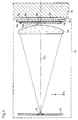
- FIG. 1 shows a schematic side view of a first interferential position measuring device for two measuring directions X and Y for measuring the relative position of two objects in incident light, in which a measuring graduation 1a of a graduation carrier 2a connected to the first object is measured by one with the scanning unit 3a connected to the second object is scanned.
- the scanning unit 3a contains a circuit board 4a, a condenser 5a and a scanning plate 6a.
- the two objects, not shown, can be formed, for example, by a cross slide and the bed of a processing machine.
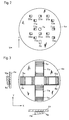
- FIG. 2 shows the circuit board 4a in a top view, on which, in addition to a light source 7a, a first group of photodetectors D1a-D6a for the measuring direction X and a second group of photodetectors T1a-T6a for the measuring direction Y are arranged.
- a position-sensitive photodetector Pa according to the invention is also located on the circuit board 4a.
- FIG. 3 shows a top view of the scanning plate 6a, which has a first scanning graduation 8a for the measuring direction X and a second scanning graduation 9a for the measuring direction Y, for example in the form of phase gratings.
- a first deflection prism 10a is arranged above the first scanning graduation 8a and a second deflection prism 11a is arranged above the second scanning graduation 9a, the inclination orientations of which can be seen from FIG.
- FIG. 4 shows an unfolded beam path for the interferential position measuring device according to FIG. 1 in a perspective illustration, for the sake of clarity only for the measuring direction X; for simplicity only certain diffracted partial beams are shown.
- a light beam bundle La emanating from the light source 7a and collimated by the condenser 5a is passed through the scanning division 8a with the Lattice constants d, whose graduation lines run perpendicular to the measuring direction X, are divided into a diffracted partial beam bundle B1 (+ 1st order), into a diffracted partial beam bundle B2 (0th order) and into a diffracted partial beam bundle B3 (-1st order).
- This cross grating 1a has the grating constant de / ⁇ 2 in the directions given by the two crossed division lines (diagonal to the measuring direction X) and thus the effective grating constant de in the measuring direction X, which is identical to the grating constant d of the scanning division 8a.
- Such a cross division 1a is defined as a structure that diffracts light beams essentially in two orthogonal directions.
- the cross grating 1a splits each diffracted partial beam bundle B1-B3 into two diffracted partial beam bundles (+ 1st order) and into two diffracted partial beam bundles (-1st order) which pass through the diagonal both in the measuring direction X and in the direction Y perpendicular to it Arrangement of the cross grating 1a can be deflected.
- the diffracted partial beams B1 are thus divided into two diffracted partial beams C1, C2 (1st order) - the two diffracted partial beams (+ 1st order) are not shown here for the sake of simplicity - the diffracted partial beams B2 in two diffracted partial beams C3, C4 (+ 1st order) and in two diffracted partial beams C5, C6 (-1st order) as well as the diffracted partial beams B3 split into two diffracted partial beams C7, C8 (1st order) and into a diffracted partial beam Ta (-1st order) - the other partial beam (-1st order) is also not shown.
- the diffracted partial beams C1-C8 then again pass through the scanning graduation 8a and come to interference with renewed diffraction.
- the resulting diffracted partial beam bundle E1 (+ 1st order) in the measuring direction X and the resulting diffracted partial beam bundle E3a (0th order) in the measuring direction X result from the interfering diffracted partial beam bundles C2 , C4 the resulting diffracted partial beam E2 (+ 1st order) in measuring direction X and the resulting diffracted partial beam E4a (0th order) in measuring direction X, from the interfering diffracted partial beams C5, C7 the resulting diffracted partial beam E3b (0th order) in Measuring direction X and the resulting diffracted partial beam E5 (1st order) in measuring direction X and from the interfering diffracted partial beams C6, C8 the resulting diffracted partial beam E4b (0th order) in measuring direction X and the resulting diffracted partial beam E6 (-1st order
- the two separating elements in the form of the deflecting prisms 10a, 11a serve to separate the diffracted partial beams E1-E6 for the two measuring directions X, Y if only one light source 7a is provided.
- gratings or polarization-optical elements can also be used as separating elements.
- the separating elements may be omitted. It is also possible with several light sources, the diffracted partial beam groups belonging to the two measuring directions X and Y with only a single photodetector group, e.g. to be recorded with a time delay.
- the photodetectors D1a + D2a, D3a + D4a and D5a + D6a are each connected in pairs and deliver the scanning signals with a mutual phase shift, preferably of 120 °, depending on the configuration of the scanning division 8a, from which the measured values for the measuring directions X are known in a known manner and Y are obtained; the same applies to the second group of photodetectors T1a-T6a.
- a different number of photodetectors can also be used for each group, e.g. three detectors.
- the partial beam bundle Ta (1st order) diffracted at the cross grating 1a falls through the scanning graduation 8a onto the position-sensitive one Photodetector Pa of the circuit board 4a.
- this position-dependent photodetector Pa is located outside the photodetectors Da, Ta in a region which is practically free of modulation even with the relative movement between the scanning unit 3a and the graduation carrier 2a with the measuring graduation 1a, and thus delivers depending on the point of impact of the diffracted partial beam Ta a direction and position dependent signal.
- Such a position-sensitive photodetector is known, for example, from "The Industrial Electro / Electronics Magazine” Issue 19/1988, Vogel Verlag and Druck KG (special edition). Further diffracted partial beams of different orders, not shown, also fall on the position-sensitive detector Ta.
- FIG. 5 shows a schematic view of a second interferential position measuring device for a measuring direction X for measuring the relative position of two objects in incident light, in which a measuring graduation 1b in the form of a linear graduation a graduation carrier 2b connected to the first object is scanned by a scanning unit 3b connected to the second object.
- the scanning unit 3b contains a laser light source 7b, a deflection U, a triple prism TP, a photodetector unit Db for the measuring direction X, and a position-sensitive photodetector Pb according to the invention.
- the two objects, not shown, can be formed, for example, by a carriage and the bed of a processing machine.
- a light beam Lb emanating from the laser light source 7b strikes the measuring graduation 1b and is split under reflection into a diffracted partial beam F1 (+ 1st order) and into a diffracted partial beam F2 (1st order).
- the two diffracted partial beams F1, F2 are deflected by the deflection U by diffraction and enter the triple prism TP in a converging manner.
- the two diffracted partial beams F1, F2 diverging again meet the deflection division U are deflected by the deflection division U by diffraction and unite on the measurement division 1b, from which it reflects onto the photodetector unit Db after diffraction and interference will.
- the photodetector unit Db generates electrical scanning signals from which measured values for the measuring direction X are obtained.
- the partial beam bundle F2 diffracted at the measuring graduation 1b falls as the partial beam bundle Tb not deflected by the deflection division U onto the position-sensitive photodetector Pb, which is located in a region free of modulation and thus, depending on the point of impact of the diffracted partial beam Tb, supplies a direction and position-dependent signal which allows the adjustment of the optimal angular position of the scanning unit 3b with respect to the measuring graduation 1b in the aforementioned manner.
- FIG. 6 shows a schematic view of a third interferential position measuring device for a measuring direction X for measuring the relative position of two objects in incident light, in which a measuring graduation 1c in the form of a linear graduation of a graduation carrier 2c connected to the first object from one connected to the second object Scanning unit 3c is scanned.
- the scanning unit 3c contains a circuit board 4c, a condenser 5c and a scanning plate 6c with a scanning graduation 8c.
- the circuit board 4c contains three photodetectors D1c, D2c, D3c for the measuring direction X as well as a first one-dimensional position-sensitive photodetector P1c and a second two-dimensional position-sensitive photodetector P2c according to the invention.
- the light beams emerging from the light source 7c are diffracted by the scanning graduation 8c and the measuring graduation 1c, reunited after reflection at the scanning graduation 8c and brought to interference and fall on the three photodetectors D1c, D2c, D3c, from whose electrical scanning signals measured values for the measuring direction X be won.
- a partial beam bundle T2c (0th order) diffracted at the measuring graduation 1c falls on the second two-dimensional position-sensitive photodetector P2c, which, depending on the point of impact of the diffracted partial beam bundle T2c, supplies a directional and position-dependent double signal that adjusts the optimal angular positions of the scanning unit 3c with respect to the measuring graduation 1c about two orthogonal axes of rotation perpendicular to the normal of the measuring graduation plane, so that a parallel adjustment of the scanning graduation 8c of the scanning unit 3c to the measuring graduation 1c can be carried out.
- the invention can be used with success both in length measuring devices and in angle measuring devices which operate according to the previously described incident light method or according to the transmitted light method in which the measuring graduation is irradiated.
Landscapes
- Physics & Mathematics (AREA)
- General Physics & Mathematics (AREA)
- Optical Transform (AREA)
- Length Measuring Devices By Optical Means (AREA)
Applications Claiming Priority (2)
| Application Number | Priority Date | Filing Date | Title |
|---|---|---|---|
| DE4105434 | 1991-02-21 | ||
| DE4105434A DE4105434A1 (de) | 1991-02-21 | 1991-02-21 | Positionsmesseinrichtung mit einer justiereinrichtung |
Publications (2)
| Publication Number | Publication Date |
|---|---|
| EP0499997A1 true EP0499997A1 (fr) | 1992-08-26 |
| EP0499997B1 EP0499997B1 (fr) | 1994-09-14 |
Family
ID=6425573
Family Applications (1)
| Application Number | Title | Priority Date | Filing Date |
|---|---|---|---|
| EP92102565A Expired - Lifetime EP0499997B1 (fr) | 1991-02-21 | 1992-02-15 | Dispositif de mesure de position avec un appareil de l'ajustement |
Country Status (2)
| Country | Link |
|---|---|
| EP (1) | EP0499997B1 (fr) |
| DE (3) | DE4105434A1 (fr) |
Cited By (1)
| Publication number | Priority date | Publication date | Assignee | Title |
|---|---|---|---|---|
| EP0679870A3 (fr) * | 1994-04-27 | 1997-04-16 | Canon Kk | Capteur optique de déplacement. |
Families Citing this family (2)
| Publication number | Priority date | Publication date | Assignee | Title |
|---|---|---|---|---|
| DE4302313C2 (de) * | 1993-01-28 | 1996-12-05 | Heidenhain Gmbh Dr Johannes | Mehrkoordinaten-Meßeinrichtung |
| DE10046818B4 (de) * | 2000-09-20 | 2008-02-07 | Dr. Johannes Heidenhain Gmbh | Positionsmesseinrichtung |
Citations (4)
| Publication number | Priority date | Publication date | Assignee | Title |
|---|---|---|---|---|
| US3269254A (en) * | 1962-12-31 | 1966-08-30 | Ibm | Optical apparatus for indicating and measuring the roll angular orientation of a movable body |
| DE2405341A1 (de) * | 1974-02-05 | 1975-08-07 | Leitz Ernst Gmbh | Anordnung zur lichtmodulation |
| GB2227558A (en) * | 1988-12-21 | 1990-08-01 | Mitutoyo Corp | Grating-interference type displacement meter apparatus |
| EP0397202A2 (fr) * | 1989-05-12 | 1990-11-14 | Canon Kabushiki Kaisha | Codeur |
Family Cites Families (3)
| Publication number | Priority date | Publication date | Assignee | Title |
|---|---|---|---|---|
| DE2844066C2 (de) * | 1978-10-10 | 1982-04-22 | Dr. Johannes Heidenhain Gmbh, 8225 Traunreut | Längen- oder Winkelmeßeinrichtung |
| US4656347A (en) * | 1984-01-30 | 1987-04-07 | Nippon Telegraph & Telephone Public Corporation | Diffraction grating position adjuster using a grating and a reflector |
| DE3541199C1 (de) * | 1985-11-21 | 1987-06-25 | Heidenhain Gmbh Dr Johannes | Lichtelektrische Positionsmesseinrichtung |
-
1991
- 1991-02-21 DE DE4105434A patent/DE4105434A1/de active Granted
- 1991-02-21 DE DE9116546U patent/DE9116546U1/de not_active Expired - Lifetime
-
1992
- 1992-02-15 EP EP92102565A patent/EP0499997B1/fr not_active Expired - Lifetime
- 1992-02-15 DE DE59200481T patent/DE59200481D1/de not_active Expired - Fee Related
Patent Citations (4)
| Publication number | Priority date | Publication date | Assignee | Title |
|---|---|---|---|---|
| US3269254A (en) * | 1962-12-31 | 1966-08-30 | Ibm | Optical apparatus for indicating and measuring the roll angular orientation of a movable body |
| DE2405341A1 (de) * | 1974-02-05 | 1975-08-07 | Leitz Ernst Gmbh | Anordnung zur lichtmodulation |
| GB2227558A (en) * | 1988-12-21 | 1990-08-01 | Mitutoyo Corp | Grating-interference type displacement meter apparatus |
| EP0397202A2 (fr) * | 1989-05-12 | 1990-11-14 | Canon Kabushiki Kaisha | Codeur |
Cited By (1)
| Publication number | Priority date | Publication date | Assignee | Title |
|---|---|---|---|---|
| EP0679870A3 (fr) * | 1994-04-27 | 1997-04-16 | Canon Kk | Capteur optique de déplacement. |
Also Published As
| Publication number | Publication date |
|---|---|
| DE4105434C2 (fr) | 1993-03-18 |
| EP0499997B1 (fr) | 1994-09-14 |
| DE59200481D1 (de) | 1994-10-20 |
| DE4105434A1 (de) | 1992-08-27 |
| DE9116546U1 (de) | 1993-01-21 |
Similar Documents
| Publication | Publication Date | Title |
|---|---|---|
| EP0262349B1 (fr) | Dispositif photoélectrique pour la mesure d'angles | |
| EP0509979B1 (fr) | Dispositif de mesure de positions photo-électronique | |
| EP1923673B1 (fr) | Dispositif de mesure de position | |
| EP0045321B1 (fr) | Procédé et dispositif de mesure optique de distances | |
| EP0163824B1 (fr) | Dispositif de mesure photo-électrique | |
| EP0482224B1 (fr) | Dispositif interférentiel de mesure pour au moins une direction de mesure | |
| EP0223009A2 (fr) | Dispositif opto-électronique de mesure de position | |
| EP0731340A2 (fr) | Dispositif pour mesurer des positions angulaires ou longitudinales | |
| DE3834676C2 (fr) | ||
| DE4302313C2 (de) | Mehrkoordinaten-Meßeinrichtung | |
| EP1085291B1 (fr) | Dispsitif pour la détermination de positions et de défaults de translation | |
| EP0754933B1 (fr) | Dispositif de mesure de positions | |
| EP0499997B1 (fr) | Dispositif de mesure de position avec un appareil de l'ajustement | |
| EP0626564B1 (fr) | Dispositif de mesure d'angles ou de longueur | |
| DE4100773C2 (de) | Interferometrische Längenmeßeinrichtung | |
| DE4132941C2 (de) | Interferentielle Meßeinrichtung für wenigstens eine Meßrichtung | |
| EP0239768A2 (fr) | Dispositif de mesure | |
| DE3939504C2 (fr) | ||
| WO2014170066A1 (fr) | Dispositif de mesure de distance interférentielle | |
| DE4105433A1 (de) | Einrichtung zur konturformpruefung an einer bearbeitungs- oder messmaschine | |
| WO1998016802A1 (fr) | Indicateur optique de position | |
| EP0316625A2 (fr) | Dispositif photo-électrique de mesure de position | |
| DE9116805U1 (de) | Interferentielle Meßeinrichtung für wenigstens eine Meßrichtung | |
| DD252234A1 (de) | Einrichtung zum messen und bearbeiten von werkstuecken | |
| DE3940387A1 (de) | Fotoelektrischer bewegungsmelder |
Legal Events
| Date | Code | Title | Description |
|---|---|---|---|
| PUAI | Public reference made under article 153(3) epc to a published international application that has entered the european phase |
Free format text: ORIGINAL CODE: 0009012 |
|
| 17P | Request for examination filed |
Effective date: 19920228 |
|
| AK | Designated contracting states |
Kind code of ref document: A1 Designated state(s): DE FR GB IT |
|
| 17Q | First examination report despatched |
Effective date: 19940126 |
|
| ITF | It: translation for a ep patent filed | ||
| GRAA | (expected) grant |
Free format text: ORIGINAL CODE: 0009210 |
|
| AK | Designated contracting states |
Kind code of ref document: B1 Designated state(s): DE FR GB IT |
|
| ET | Fr: translation filed | ||
| REF | Corresponds to: |
Ref document number: 59200481 Country of ref document: DE Date of ref document: 19941020 |
|
| GBT | Gb: translation of ep patent filed (gb section 77(6)(a)/1977) |
Effective date: 19940922 |
|
| PLBE | No opposition filed within time limit |
Free format text: ORIGINAL CODE: 0009261 |
|
| STAA | Information on the status of an ep patent application or granted ep patent |
Free format text: STATUS: NO OPPOSITION FILED WITHIN TIME LIMIT |
|
| 26N | No opposition filed | ||
| REG | Reference to a national code |
Ref country code: GB Ref legal event code: IF02 |
|
| PGFP | Annual fee paid to national office [announced via postgrant information from national office to epo] |
Ref country code: FR Payment date: 20050210 Year of fee payment: 14 |
|
| PGFP | Annual fee paid to national office [announced via postgrant information from national office to epo] |
Ref country code: GB Payment date: 20060221 Year of fee payment: 15 |
|
| PGFP | Annual fee paid to national office [announced via postgrant information from national office to epo] |
Ref country code: IT Payment date: 20060228 Year of fee payment: 15 |
|
| REG | Reference to a national code |
Ref country code: FR Ref legal event code: ST Effective date: 20061031 |
|
| GBPC | Gb: european patent ceased through non-payment of renewal fee |
Effective date: 20070215 |
|
| PG25 | Lapsed in a contracting state [announced via postgrant information from national office to epo] |
Ref country code: FR Free format text: LAPSE BECAUSE OF NON-PAYMENT OF DUE FEES Effective date: 20060228 |
|
| PG25 | Lapsed in a contracting state [announced via postgrant information from national office to epo] |
Ref country code: GB Free format text: LAPSE BECAUSE OF NON-PAYMENT OF DUE FEES Effective date: 20070215 |
|
| PGFP | Annual fee paid to national office [announced via postgrant information from national office to epo] |
Ref country code: DE Payment date: 20080219 Year of fee payment: 17 |
|
| PG25 | Lapsed in a contracting state [announced via postgrant information from national office to epo] |
Ref country code: IT Free format text: LAPSE BECAUSE OF NON-PAYMENT OF DUE FEES Effective date: 20070215 |
|
| PG25 | Lapsed in a contracting state [announced via postgrant information from national office to epo] |
Ref country code: DE Free format text: LAPSE BECAUSE OF NON-PAYMENT OF DUE FEES Effective date: 20090901 |