EP0500080A2 - Système d'autodiagnostic et d'autoréparation pour un appareil de formation d'images - Google Patents
Système d'autodiagnostic et d'autoréparation pour un appareil de formation d'images Download PDFInfo
- Publication number
- EP0500080A2 EP0500080A2 EP92102773A EP92102773A EP0500080A2 EP 0500080 A2 EP0500080 A2 EP 0500080A2 EP 92102773 A EP92102773 A EP 92102773A EP 92102773 A EP92102773 A EP 92102773A EP 0500080 A2 EP0500080 A2 EP 0500080A2
- Authority
- EP
- European Patent Office
- Prior art keywords
- fault
- degradation
- data
- image forming
- forming apparatus
- Prior art date
- Legal status (The legal status is an assumption and is not a legal conclusion. Google has not performed a legal analysis and makes no representation as to the accuracy of the status listed.)
- Granted
Links
Images



Classifications
-
- G—PHYSICS
- G06—COMPUTING OR CALCULATING; COUNTING
- G06F—ELECTRIC DIGITAL DATA PROCESSING
- G06F11/00—Error detection; Error correction; Monitoring
- G06F11/07—Responding to the occurrence of a fault, e.g. fault tolerance
- G06F11/0703—Error or fault processing not based on redundancy, i.e. by taking additional measures to deal with the error or fault not making use of redundancy in operation, in hardware, or in data representation
- G06F11/079—Root cause analysis, i.e. error or fault diagnosis
-
- G—PHYSICS
- G03—PHOTOGRAPHY; CINEMATOGRAPHY; ANALOGOUS TECHNIQUES USING WAVES OTHER THAN OPTICAL WAVES; ELECTROGRAPHY; HOLOGRAPHY
- G03G—ELECTROGRAPHY; ELECTROPHOTOGRAPHY; MAGNETOGRAPHY
- G03G15/00—Apparatus for electrographic processes using a charge pattern
- G03G15/55—Self-diagnostics; Malfunction or lifetime display
-
- G—PHYSICS
- G06—COMPUTING OR CALCULATING; COUNTING
- G06F—ELECTRIC DIGITAL DATA PROCESSING
- G06F11/00—Error detection; Error correction; Monitoring
- G06F11/07—Responding to the occurrence of a fault, e.g. fault tolerance
- G06F11/0703—Error or fault processing not based on redundancy, i.e. by taking additional measures to deal with the error or fault not making use of redundancy in operation, in hardware, or in data representation
- G06F11/0706—Error or fault processing not based on redundancy, i.e. by taking additional measures to deal with the error or fault not making use of redundancy in operation, in hardware, or in data representation the processing taking place on a specific hardware platform or in a specific software environment
- G06F11/0733—Error or fault processing not based on redundancy, i.e. by taking additional measures to deal with the error or fault not making use of redundancy in operation, in hardware, or in data representation the processing taking place on a specific hardware platform or in a specific software environment in a data processing system embedded in an image processing device, e.g. printer, facsimile, scanner
-
- G—PHYSICS
- G06—COMPUTING OR CALCULATING; COUNTING
- G06F—ELECTRIC DIGITAL DATA PROCESSING
- G06F11/00—Error detection; Error correction; Monitoring
- G06F11/22—Detection or location of defective computer hardware by testing during standby operation or during idle time, e.g. start-up testing
- G06F11/2257—Detection or location of defective computer hardware by testing during standby operation or during idle time, e.g. start-up testing using expert systems
-
- G—PHYSICS
- G03—PHOTOGRAPHY; CINEMATOGRAPHY; ANALOGOUS TECHNIQUES USING WAVES OTHER THAN OPTICAL WAVES; ELECTROGRAPHY; HOLOGRAPHY
- G03G—ELECTROGRAPHY; ELECTROPHOTOGRAPHY; MAGNETOGRAPHY
- G03G2215/00—Apparatus for electrophotographic processes
- G03G2215/00025—Machine control, e.g. regulating different parts of the machine
- G03G2215/00118—Machine control, e.g. regulating different parts of the machine using fuzzy logic
Definitions
- the present invention relates to a self-diagnosis and self-repair system, and more particularly, to a system capable of making self-diagnosis of the degraded state, the operating state and the like of an apparatus by utilizing artificial intelligence and knowledge engineering which have been studied extensively in recent years as well as adopting fuzzy inference and making self-repair thereof as required.
- expert systems utilizing artificial intelligence (so-called AI) techniques have been being studied extensively in recent years for the purpose of realizing labor saving in maintenance work and long-term automatic operation.
- AI artificial intelligence
- the expert systems include one for making self-diagnose to judge whether or not a fault is caused in an apparatus and making self-repair of the fault caused.
- an actuator corresponding to a sensor is basically made to operate on the basis of an output of the sensor. That is, one type of automatic control and fault diagnosis has been made by a predetermined combination of a sensor and an actuator. Accordingly, a certain sensor basically corresponds to a particular actuator, and the relationship therebetween has been stationary. Therefore, the conventional system has the following disadvantages: (a) The relationship between parameters of the sensor and parameters of the actuator must be clearly expressed numerically. (b) From the reason mentioned in the above item (a), the relationship between parameters of the sensor and parameters of the actuator depends largely on an object. Accordingly, the conventional system is lacking in versatility, that is, cannot be utilized for a variety of objects.
- Qualitative inference used in the above described self-diagnosis and/or self-repair system already proposed is complete as the approach of determining the qualitative transition from a group of equations and the initial state.
- the qualitative inference has such an inevitable destiny that an ambiguous expression is not admitted as the state representation of an objective system (machine) because inference in the form of a qualitative, that is, symbolic expression is drawn.
- the qualitative inference is insufficient as the approach of making fault diagnosis and repair by handling information such as "ambiguous information" often seen in the maintenance activity, for example, information "this may be normal or abnormal" as the state of the machine.
- the inventors of the present application have invented a self-diagnosis and self-repair system having a higher degree of completion by combining the fuzzy theory which is a theory mathematically handling ambiguity with the qualitative inference used in the above descried self-diagnosis and/or self-repair system already proposed.
- An object of the present invention is to provide an image forming apparatus having a system capable of developing inference admitting ambiguity from the point of view of maintenance, making self-diagnosis of the state of an apparatus using the inference and making self-repair thereof as required.
- the self-diagnosis and self-repair system calculates as a fuzzy qualitative value the amount of degradation relative to the time elapsed after the image forming apparatus starts to be used up to the present time on the basis of state data sensed by sensor means as well as degradation data containing degradation factors and respective membership functions of the degradation factors.
- the value of a parameter changed by the amount of degradation calculated is converted into a fuzzy qualitative value using membership functions of the parameter, and is replaced with an expression used on qualitative data.
- data sensed by a plurality of sensor means is converted into a fuzzy qualitative value using the membership functions of the parameter, and it is judged on the basis of the fuzzy qualitative value whether or not a fault exists. If it is judged that a fault exists, fault diagnosis is made utilizing as an initial value the value of the parameter changed by the above described amount of degradation. The result of the diagnosis is outputted as an expression having ambiguity.
- the causes of the fault are specified by comparing the fuzzy qualitative value obtained by the conversion from the output of the sensor means with the result obtained by the fault diagnosis. More specifically, when a plurality of fault candidates are taken up as a result of the fault diagnosis, a fault candidate which best coincides with the actual state of the apparatus is examined. Consequently, the actual fault state is outputted more accurately. A predetermined one of a plurality of actuators is operated by repair means to repair the fault.
- the quantity space is a finite set obtained by symbolically representing a set of real numbers by a landmark which is a characteristic value having a physical meaning and a section enclosed by the landmark. Accordingly, either one of a boundary value or a section value is only taken as the qualitative value.
- a self-diagnosis and/or self-repair system in an ideal objective machine taken as an example, it makes sense to judge whether a certain value is a landmark value or a section value.
- a quantitative value obtained by measurements is converted into a qualitative expression and inference is drawn on the basis of the expression in the actual world, it may not be appropriate that the quantitative value obtained by measurements is only alternatively converted into a landmark value or a section value.
- the reason for this is that "ambiguous information" is seen in the maintenance activity, as described above, so that there can actually occur the situation where the quantitative value may be a landmark value or a section value.
- the fuzzy theory is a theory of mathematically handling ambiguity.
- the expression of a set in the fuzzy theory is characterized in that an intermediate state where it is not clear whether or not a certain element belongs to the set is indicated by decimal fractions from 0.0 to 1.0 as the degree to which the element belongs to the set.
- the intermediate state which cannot be represented by a conventional set can be represented by using this form of expression.
- a function for defining the degree to which a certain element belongs to a certain set (grade) is referred to as a "membership function".
- an expression having ambiguity added to a qualitative expression becomes possible by introducing the concept of a fuzzy set represented using this membership function. More specifically, in the present invention, the value of a variable is represented as a set of a conventional qualitative value and the degree to which it belongs to the qualitative value (grade). Such a form of expression will be referred to as a "fuzzy qualitative value”.
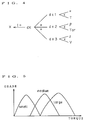
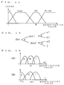
- a certain variable when the value of a certain variable is represented by a fuzzy qualitative value in a quantity space shown in Fig. 1, the value is expressed, for example, as follows: (Normal : 0.4, (Normal, nil) : 0.6) It is possible to admit ambiguity by using this method of representation by a fuzzy qualitative value when sensor information is made use of for inference. More specifically, in a fault diagnosis system using the qualitative inference previously proposed, a certain constant range has been determined as a range of normal values. If a quantitative value obtained from a sensor is in the range, it is considered that the qualitative value is on a landmark of "normal values", to draw qualitative inference.
- membership functions are used for the operation of converting a quantitative value obtained from a sensor into a qualitative expression.
- membership functions such as "a normal value (Normal; hereinafter abbreviated as N)", “larger than a normal value (Normal, nil; hereinafter abbreviated as N, nil)", and “smaller than a normal value (0, Normal; hereinafter abbreviated as 0, N)" are previously determined on a space of real numbers of the sensor, as shown in Fig. 2.
- a quantitative value obtained from the sensor is mapped on the space shown in Fig. 2, to convert the quantitative value into a qualitative expression admitting ambiguity.
- the maximum value thereof is adopted.
- the maximum value thereof that is, 0.7 is adopted as the grade with respect to the qualitative value (0, n) of Zf.
- the maximum value thereof that is, 0.3 is selected.
- This propagation method is an algorithm for sequentially propagating the value of a parameter whose value is already determined to the other parameters using the relationship between the parameters to determine parameters in the entire system.
- the propagation procedure uses a method of determining an unfixed parameter out of parameters in the binomial relation or the trinomial relation using the parameters already determined and the relationship therebetween from the above described fuzzy operation rule.
- the specific inference method will be made clear from the concrete examples as described later.
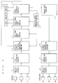
- Fig. 3 is a block diagram showing the construction of a system according to one embodiment of the present invention.
- This system comprises a plurality of sensors 1a, 1b and 1c installed on an objective machine (more concretely, a small-sized electrophotographic copying machine or the like) and a plurality of actuators 6a, 6b and 6c for changing the operating state or the like of the objective machine.
- an objective machine more concretely, a small-sized electrophotographic copying machine or the like
- actuators 6a, 6b and 6c for changing the operating state or the like of the objective machine.
- the plurality of sensors 1a, 1b and 1c are respectively used for sensing the change of elements of the objective machine or relevant states among the machine elements which occurs by the operation of the objective machine.
- Information which are taken in from the plurality of sensors 1a, 1b and 1c, respectively, are amplified by an amplification circuit 2, are converted from analog signals to digital signals by an A/D conversion circuit 3, and are applied to a digital signal/FQ value (fuzzy qualitative value) conversion portion 11.
- the digital signal/FQ value conversion portion 11 is a portion for converting the digital signal applied from the A/D conversion circuit 3 into a fuzzy qualitative value, that is, has the converting function for representing the digital signal by a qualitative value (for example, any one of three symbols, for example, "small”, “normal”, and “large”) and a grade (a numerical value of 0.0 to 1.0).
- the signals applied from the sensors 1a, 1b and 1c are respectively converted into qualitative information represented by fuzzy qualitative values, thereby to make it easy to make an approach to fault diagnosis.
- Fuzzy qualitative values of parameters required to calculate the amount of degradation of each of components out of the fuzzy qualitative values outputted from the digital signal/FQ value conversion portion 11 are sequentially applied to a long-term simulation portion 12, a short-term simulation portion 13, and a fault diagnosis portion 14,
- the long-term simulation portion 12 is a portion for simulating the amount of degradation with age of each of the components constituting the objective machine.
- the short-term simulation portion 13 is a portion for simulating the present state of the objective machine.
- the fault diagnosis portion 14 is a portion for performing function evaluation using fuzzy qualitative values of parameters required to perform fault evaluation out of the fuzzy qualitative values outputted from the digital signal/FQ value conversion portion 11 to specify the fault symptom as well as derive the causes of the fault from the fault symptom.
- a step (fault diagnosis) for deriving the causes of the fault from the fault symptom specified in the fault diagnosis portion 14 is carried out on the basis of inference using no fuzzy inference used in the self-diagnosis and/or self-repair system disclosed in the above described prior specification of the applicant.
- the objective model storage portion 15 previously stores a "substance model” in which an objective machine is grasped from a physical point of view and is represented by parameters as a combination of a plurality of elements at a substance level, a "parameter model” in which the objective machine is represented as a combined tree of the parameters, initial values of the respective parameters, membership functions of the respective parameters, the corresponding relationship between the amount of degradation and the actual change, a reference value for fault judgment, fault candidate knowledge, and the like.
- These types of knowledge stored in the objective model storage portion 15 are made use of when the digital signal/FQ value conversion portion 11, the long-term simulation portion 12, the short-term simulation portion 13, or the fault diagnosis portion 14 performs processing.
- a fault simulation portion 16 is a portion for simulating a fault in cooperation with the short-term simulation portion 13 and the fault diagnosis portion 14.
- the present embodiment and the present invention are characterized in that a system is provided with two constituent elements, that is, a long-term simulation portion and a short-term simulation portion.
- the two constituent elements will be described in more detail.
- LSIM long-term simulation
- the relationship between the amount of degradation and degradation factor parameters for estimating the amount of degradation is previously represented using a qualitative expression for each component or for each group of relevant components.
- factors defining the amount of degradation include the time T elapsed after the gear starts to be used, a torque Tor applied in a state where the gear is used, and a peripheral speed V.
- the relationship between the degradation factor parameters and the degradation speed dX is shown in Fig. 4.
- a quantity space of each of the degradation factor parameters that is, T, Tor and V, constants of proportion ⁇ , ⁇ and ⁇ , the degradation speed dX, and the amount of degradation X in this case is a quantity space which is not dependent on the objective machine in which the components are used but is dependent on (intrinsic to) the components.
- This quantity space can be represented by determining membership functions. For example, it can be represented as shown in Fig. 5 by taking as an example the torque Tor which is one of the degradation factor parameters.
- the above described quantity space and relationship between the values are previously established with respect to each of the degradation factor parameters, the constants of proportion, the degradation speed, and the amount of degradation, and are stored in the objective model storage portion 15 as knowledge which is component dependent (which is not objective machine dependent).
- the LSIM is made utilizing such knowledge which is component dependent for each certain constant period or at arbitrary timing to esti mate the amount of degradation.
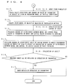
- a value (quantitative value) under conditions under which the component is used in the objective machine is first mapped in the quantity space of the degradation factor parameter (see Fig. 5), thereby to convert the degradation factor parameter into a fuzzy qualitative value.
- the values of the degradation factor parameter represented by the fuzzy qualitative value and the relationship between the values of the parameter are then used to find the degradation speed.
- the time differences in the amount of degradation within a constant period thus found are added up, thereby to find the total amount of degradation of the component (see Fig. 4).
- the amount of degradation finally found is obtained in the form of, for example, (middle: 0.3, large: 0.7).
- the amount of degradation found in this LSIM is not for estimating the physical quantities on the parameter model of the objective machine. For example, even if the amount of degradation of a gear (the amount of wear of a gear) is found by the LSIM, it is not found how change occurs on the parameter model of the objective machine. The effect exerted on the objective machine by the degradation will be found from a predetermined amount of degradation and the relationship between the values of function parameters on the parameter model, as described later.
- a short-term simulation (hereinafter referred to as SSIM) is a simulation for determining the state of the present objective machine.
- the state of the objective machine is represented by a set of physical quantities indicating attributes of the respective components constituting the objective machine.
- the SSIM is made on the parameter model in which the physical quantities are related to each other by a qualitative equation.
- the SSIM inference method uses the above described fuzzy qualitative inference.
- the propagation method is used as an algorithm for the fuzzy qualitative inference. Description is now made of the propagation procedure in this propagation method.
- Inference begins in a state where the respective values of constant parameters, parameters determined by values obtained from the sensors, and parameters determined by the LSIM are determined.
- the state of the entire objective machine that is, the values of all the parameters are determined by the SSIM.
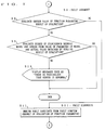
- the state of the objective machine at the time point is previously sensed by the sensor provided for the objective machine (step S1), and the value of each of parameters obtained by the sensing is converted into a fuzzy qualitative value (step S2).
- the sensing of the value of the parameter in the step S1 is achieved by, if there is provided a sensor, the sensor (for example, the quantity of light H1 of a halogen lamp is measured by an AE sensor, as described later).
- the time elapsed after the objective machine starts to be used is counted by, for example, a counter contained in the objective machine, and the value of the counter is read out as a quantitative value indicating the time.
- the sensing in the step S1 may be achieved by using a method in which a service man or the like manually measures the objective machine and inputs the measured value into a system if no sensor and counter are contained in the objective machine.
- the repair plan portion 17 is a composition portion for inferring a repair plan for repairing, when a fault exists, the fault as well as deriving repair work.
- the inference of the repair plan and the derivation of the repair work make use of non-fuzzy qualitative inference using no fuzzy theory, similarly to the inference in the self-diagnosis and/or self-repair system already proposed.
- the repair work outputted from the repair plan portion 17 is converted into a digital signal in a symbol-to-digital signal conversion portion 18.
- the digital signal converted is converted into an analog signal in a D/A conversion circuit 4, is amplified in an amplification circuit 5, and is applied to a plurality of actuators 6a, 6b and 6c so that the actuators 6a, 6b and 6c are selectively operated, thereby to perform the repair work.
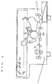
- Fig. 9 is an illustration showing a small-sized electrophotographic copying machine serving as a specific objective machine.
- reference numeral 21 designates a photosensitive drum
- reference numeral 22 designates a principal electro static charger
- reference numeral 23 designates a halogen lamp for copy illumination
- reference numeral 24 designates a developing device
- reference numeral 25 designates a transfer charger.
- This specific objective machine is provided with, for example, three sensors 1a, 1b and 1c. More specifically, the sensor 1a is an AE sensor for measuring the quantity of light incident on the photosensitive drum 21, the sensor 1b is a surface potential sensor for measuring a surface potential of the photosensitive drum 21, and the sensor 1c is a densitometer for measuring the density of a picture image copied on paper.
- the sensor 1a is an AE sensor for measuring the quantity of light incident on the photosensitive drum 21
- the sensor 1b is a surface potential sensor for measuring a surface potential of the photosensitive drum 21
- the sensor 1c is a densitometer for measuring the density of a picture image copied on paper.
- actuators are provided, which are not shown in Fig. 9. That is, three volumes, that is, a principal charge volume VR1 for changing a principal charge voltage of the photosensitive drum 21, a lamp volume AVR for controlling the quantity of light of the halogen lamp 23, and a transfer volume VR2 for controlling a transfer voltage between the photosensitive drum 21 and copy paper are provided as the actuators.
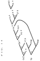
- the electrophotographic copying machine shown in Fig. 9 is looked at from a physical point of view, the electrophotographic copying machine is expressed as a combination of a plurality of elements at a substance level, and behaviors and attributes of the respective elements as well as the combinational relationship among the respective elements are expressed qualitatively using parameters, as shown in Table 2.
- the form of expression will be referred to as a "substance model”.
- the "substance model” and the “parameter model” are referred to as an “objective model” correctively.
- the “objective model” is qualitative data common to image forming apparatuses which is also made use of for fault repair as described later.
- the respective contents of the substance model and the parameter model are stored in the objective model storage portion 15 (see Fig. 3).
- parameters H1, D, Vn, ⁇ , Vb, ⁇ 0, ⁇ and Asp basic to the construction of this objective machine, sensor parameters X, Vs and Os obtained from the sensors, and parameters which may be degraded have respectively qualitative fuzzy quantity spaces shown in Fig. 11.
- This qualitative fuzzy quantity space can be arbitrarily created, and are previously created by determining membership functions for each parameter and stored in the objective model storage portion 15.
- a degradation model intrinsic to a predetermined component out of the components constituting the electrophotographic copying machine according to the present embodiment is constructed.
- description is made considering that only an exposure portion is degraded for simplification.
- Fig. 12 shows a degradation model
- Fig. 13 shows a qualitative fuzzy quantity space on the degradation model of each of the parameters.
- Table 3 shows the corresponding relationship between the amount of degradation XX and the actual change
- Table 4 (A) and (B) show an operation rule.
- p (H1Cut) in the above described table 3 indicates the degree p to which there occurs such a phenomenon that the halogen lamp is cut off (H1Cut).
- the degree p to which a phenomenon occurs is taken as 1.0 when it is not changed with time, which is not shown in the table 3.
- the degree p to which there occurs such a phenomenon that the halogen lamp is faulty (H1Out) is 1.0.
- Example 1 Example in which machine is normal one month (T1) after it is new
- the quantity of light of the sensor 1a measured using a reference white document is used as the value of a parameter H1
- the quantity of light of the sensor 1a measured using a document having a predetermined density is used as the value of a parameter X.
- a surface potential Vs after exposure and a toner density Os on output paper are respectively measured by the sensors 1b and 1c.
- time information at the time point where the sensor values of the above described respective parameters are measured is used as T.
- H1 (m : 1.0)
- T (s : 1.0)
- quantitative values of X, Vs and Os obtained from the measurements of the above described values of the parameters are respectively mapped in qualitative fuzzy quantity spaces intrinsic thereto, as shown in Fig. 11, to obtain the following sensor values of the parameters:
- X ((0, N) : 0.1, N : 0.9)
- Vs (N : 1.0)
- Os ((0, N) : 0.1, N : 0.9)
- Example 2 Example in which machine fails one month (T1) after it is new, similarly to Example 1
- Example 3 Example in which machine is degraded n months (nT1) after it starts to be used
- Example 4 Case where fault occurs under same conditions as Example 3
Landscapes
- Engineering & Computer Science (AREA)
- Theoretical Computer Science (AREA)
- Physics & Mathematics (AREA)
- General Engineering & Computer Science (AREA)
- General Physics & Mathematics (AREA)
- Quality & Reliability (AREA)
- Computer Vision & Pattern Recognition (AREA)
- Health & Medical Sciences (AREA)
- Biomedical Technology (AREA)
- Computer Hardware Design (AREA)
- Control Or Security For Electrophotography (AREA)
- Processing Or Creating Images (AREA)
- Devices For Executing Special Programs (AREA)
- Facsimiles In General (AREA)
- Testing And Monitoring For Control Systems (AREA)
Applications Claiming Priority (2)
| Application Number | Priority Date | Filing Date | Title |
|---|---|---|---|
| JP3025804A JPH04264566A (ja) | 1991-02-20 | 1991-02-20 | 画像形成装置のための自己診断システム |
| JP25804/91 | 1991-02-20 |
Publications (3)
| Publication Number | Publication Date |
|---|---|
| EP0500080A2 true EP0500080A2 (fr) | 1992-08-26 |
| EP0500080A3 EP0500080A3 (en) | 1993-02-24 |
| EP0500080B1 EP0500080B1 (fr) | 1996-02-07 |
Family
ID=12176051
Family Applications (1)
| Application Number | Title | Priority Date | Filing Date |
|---|---|---|---|
| EP92102773A Expired - Lifetime EP0500080B1 (fr) | 1991-02-20 | 1992-02-19 | Système d'autodiagnostic et d'autoréparation pour un appareil de formation d'images |
Country Status (4)
| Country | Link |
|---|---|
| US (1) | US5452438A (fr) |
| EP (1) | EP0500080B1 (fr) |
| JP (1) | JPH04264566A (fr) |
| DE (1) | DE69208110T2 (fr) |
Cited By (3)
| Publication number | Priority date | Publication date | Assignee | Title |
|---|---|---|---|---|
| EP0589135A2 (fr) * | 1992-09-24 | 1994-03-30 | Kabushiki Kaisha Toshiba | Appareil de formation d'images et procédé de la fabrication |
| EP0565761B1 (fr) * | 1992-04-15 | 1997-07-09 | Mita Industrial Co. Ltd. | Appareil de formation d'images avec un système d'autodiagnostic |
| GB2395802A (en) * | 2002-10-31 | 2004-06-02 | Gen Electric | Method, system and program product for establishing a self-diagnosing and self-repairing automated system. |
Families Citing this family (10)
| Publication number | Priority date | Publication date | Assignee | Title |
|---|---|---|---|---|
| FR2748132B1 (fr) * | 1996-04-26 | 1998-05-29 | Sgs Thomson Microelectronics | Procede de gestion d'un systeme electronique |
| US6856859B1 (en) | 1998-12-31 | 2005-02-15 | Kimberly-Clark Worldwide, Inc. | Method of controlling cross-direction alignment in manufacturing process |
| US6260188B1 (en) | 1998-12-31 | 2001-07-10 | Kimberly-Clark Worldwide, Inc. | Control model |
| US6253159B1 (en) | 1998-12-31 | 2001-06-26 | Kimberly-Clark Worldwide, Inc. | Process control using multiple detections |
| US6266436B1 (en) | 1999-04-09 | 2001-07-24 | Kimberly-Clark Worldwide, Inc. | Process control using multiple detections |
| US6404910B1 (en) | 1998-12-31 | 2002-06-11 | Kimberly-Clark Worldwide, Inc. | Making absorbent articles using vision imaging system |
| US6553270B1 (en) | 1999-06-30 | 2003-04-22 | Kimberly-Clark Worldwide, Inc. | Proactive control of a process after the beginning of a destabilizing event |
| US7103507B2 (en) * | 2004-09-28 | 2006-09-05 | Dimitry Gorinevsky | Structure health monitoring system and method |
| US20160321125A1 (en) * | 2015-04-30 | 2016-11-03 | Samsung Electronics Co., Ltd. | Self-diagnosis device and device including the same |
| US10466668B2 (en) * | 2016-03-22 | 2019-11-05 | Canon Kabushiki Kaisha | Information processing apparatus, system, control method, and storage medium |
Family Cites Families (11)
| Publication number | Priority date | Publication date | Assignee | Title |
|---|---|---|---|---|
| US4277162A (en) * | 1978-07-13 | 1981-07-07 | Ricoh Company, Ltd. | Electrophotographic apparatus comprising density sensor means |
| JPS6015651A (ja) * | 1983-07-08 | 1985-01-26 | Fuji Xerox Co Ltd | 複写機の制御装置 |
| NL8702166A (nl) * | 1987-09-11 | 1989-04-03 | Oce Nederland Bv | Belichtingsinrichting met een verouderings correctiesysteem voor een led printer. |
| JP2635087B2 (ja) * | 1988-03-25 | 1997-07-30 | 株式会社日立製作所 | プロセス制御方法 |
| US4879577A (en) * | 1988-04-19 | 1989-11-07 | International Business Machines Corporation | Method and apparatus for controlling the electrostatic parameters of an electrophotographic reproduction device |
| JPH01309101A (ja) * | 1988-06-08 | 1989-12-13 | Hitachi Ltd | 適応知識推定方法 |
| EP0390563A3 (fr) * | 1989-03-31 | 1992-12-02 | Matsushita Electric Industrial Co., Ltd. | Dispositif d'inférence floue multi-étage |
| JPH02302828A (ja) * | 1989-05-18 | 1990-12-14 | Ricoh Co Ltd | 診断型エキスパートシステム |
| JPH0310269A (ja) * | 1989-06-07 | 1991-01-17 | Canon Inc | 画像形成装置 |
| JPH0336136A (ja) * | 1989-06-30 | 1991-02-15 | Omron Corp | 紙葉類搬送装置 |
| JPH03147488A (ja) * | 1989-11-01 | 1991-06-24 | Olympus Optical Co Ltd | 画像フリーズ用信号処理装置 |
-
1991
- 1991-02-20 JP JP3025804A patent/JPH04264566A/ja active Pending
-
1992
- 1992-02-11 US US07/833,685 patent/US5452438A/en not_active Expired - Fee Related
- 1992-02-19 EP EP92102773A patent/EP0500080B1/fr not_active Expired - Lifetime
- 1992-02-19 DE DE69208110T patent/DE69208110T2/de not_active Expired - Fee Related
Cited By (4)
| Publication number | Priority date | Publication date | Assignee | Title |
|---|---|---|---|---|
| EP0565761B1 (fr) * | 1992-04-15 | 1997-07-09 | Mita Industrial Co. Ltd. | Appareil de formation d'images avec un système d'autodiagnostic |
| EP0589135A2 (fr) * | 1992-09-24 | 1994-03-30 | Kabushiki Kaisha Toshiba | Appareil de formation d'images et procédé de la fabrication |
| GB2395802A (en) * | 2002-10-31 | 2004-06-02 | Gen Electric | Method, system and program product for establishing a self-diagnosing and self-repairing automated system. |
| GB2395802B (en) * | 2002-10-31 | 2006-04-26 | Gen Electric | Method, system and program product for establishing a self-diagnosing and self-repairing automated system |
Also Published As
| Publication number | Publication date |
|---|---|
| JPH04264566A (ja) | 1992-09-21 |
| EP0500080B1 (fr) | 1996-02-07 |
| US5452438A (en) | 1995-09-19 |
| EP0500080A3 (en) | 1993-02-24 |
| DE69208110T2 (de) | 1996-11-14 |
| DE69208110D1 (de) | 1996-03-21 |
Similar Documents
| Publication | Publication Date | Title |
|---|---|---|
| US5467355A (en) | Image forming apparatus provided with self-diagnosis system | |
| JP2534387B2 (ja) | 画像形成装置のための自己診断システム | |
| US5452438A (en) | Image forming apparatus provided with self-diagnosis and self-repair system | |
| EP0593018B1 (fr) | Appareil de formation d'images muni d'une fonction d'autoréparation | |
| JP2534385B2 (ja) | 画像形成装置のための自己診断および自己修復システム | |
| JPH04274455A (ja) | 自己診断修復システムを備えた画像形成装置 | |
| JPH04273260A (ja) | 自己診断修復システムを備えた画像形成装置 | |
| JPH04274456A (ja) | 自己診断修復システムを備えた画像形成装置 | |
| JPH04274458A (ja) | 自己診断修復システムを備えた画像形成装置 | |
| JP2534386B2 (ja) | 画像形成装置のための自己診断および自己修復システム | |
| JPH04273262A (ja) | 画像形成装置のための自己診断システム | |
| JPH04264567A (ja) | 画像形成装置のための自己診断システム | |
| JPH04274461A (ja) | 自己診断システムを備えた画像形成装置 | |
| JPH04273263A (ja) | 画像形成装置のための自己診断システム | |
| JPH04264460A (ja) | 自己診断修復システムを備えた画像形成装置 | |
| JPH04264458A (ja) | 自己診断修復システムを備えた画像形成装置 | |
| JPH04264459A (ja) | 自己診断修復システムを備えた画像形成装置 | |
| JPH04273261A (ja) | 自己診断修復システムを備えた画像形成装置 | |
| JPH04264568A (ja) | 自己診断システムを備えた画像形成装置 | |
| JPH04273258A (ja) | 自己診断修復システムを備えた画像形成装置 | |
| JPH04274459A (ja) | 画像形成装置のための自己診断システム | |
| JPH04264565A (ja) | 自己診断修復システムを備えた画像形成装置 | |
| JPH04274457A (ja) | 自己診断修復システムを備えた画像形成装置 | |
| JPH04274460A (ja) | 画像形成装置のための自己診断システム | |
| JPH04273264A (ja) | 自己診断システムを備えた画像形成装置 |
Legal Events
| Date | Code | Title | Description |
|---|---|---|---|
| PUAI | Public reference made under article 153(3) epc to a published international application that has entered the european phase |
Free format text: ORIGINAL CODE: 0009012 |
|
| AK | Designated contracting states |
Kind code of ref document: A2 Designated state(s): DE FR GB IT |
|
| PUAL | Search report despatched |
Free format text: ORIGINAL CODE: 0009013 |
|
| AK | Designated contracting states |
Kind code of ref document: A3 Designated state(s): DE FR GB IT |
|
| 17P | Request for examination filed |
Effective date: 19930422 |
|
| 17Q | First examination report despatched |
Effective date: 19940316 |
|
| GRAA | (expected) grant |
Free format text: ORIGINAL CODE: 0009210 |
|
| AK | Designated contracting states |
Kind code of ref document: B1 Designated state(s): DE FR GB IT |
|
| ET | Fr: translation filed | ||
| REF | Corresponds to: |
Ref document number: 69208110 Country of ref document: DE Date of ref document: 19960321 |
|
| ITF | It: translation for a ep patent filed | ||
| PLBE | No opposition filed within time limit |
Free format text: ORIGINAL CODE: 0009261 |
|
| STAA | Information on the status of an ep patent application or granted ep patent |
Free format text: STATUS: NO OPPOSITION FILED WITHIN TIME LIMIT |
|
| 26N | No opposition filed | ||
| PGFP | Annual fee paid to national office [announced via postgrant information from national office to epo] |
Ref country code: FR Payment date: 19980210 Year of fee payment: 7 |
|
| PGFP | Annual fee paid to national office [announced via postgrant information from national office to epo] |
Ref country code: GB Payment date: 19990218 Year of fee payment: 8 |
|
| PGFP | Annual fee paid to national office [announced via postgrant information from national office to epo] |
Ref country code: DE Payment date: 19990301 Year of fee payment: 8 |
|
| PG25 | Lapsed in a contracting state [announced via postgrant information from national office to epo] |
Ref country code: FR Free format text: LAPSE BECAUSE OF NON-PAYMENT OF DUE FEES Effective date: 19991029 |
|
| REG | Reference to a national code |
Ref country code: FR Ref legal event code: ST |
|
| PG25 | Lapsed in a contracting state [announced via postgrant information from national office to epo] |
Ref country code: GB Free format text: LAPSE BECAUSE OF NON-PAYMENT OF DUE FEES Effective date: 20000219 |
|
| GBPC | Gb: european patent ceased through non-payment of renewal fee |
Effective date: 20000219 |
|
| PG25 | Lapsed in a contracting state [announced via postgrant information from national office to epo] |
Ref country code: DE Free format text: LAPSE BECAUSE OF NON-PAYMENT OF DUE FEES Effective date: 20001201 |
|
| PG25 | Lapsed in a contracting state [announced via postgrant information from national office to epo] |
Ref country code: IT Free format text: LAPSE BECAUSE OF NON-PAYMENT OF DUE FEES;WARNING: LAPSES OF ITALIAN PATENTS WITH EFFECTIVE DATE BEFORE 2007 MAY HAVE OCCURRED AT ANY TIME BEFORE 2007. THE CORRECT EFFECTIVE DATE MAY BE DIFFERENT FROM THE ONE RECORDED. Effective date: 20050219 |