EP0500090A2 - Mécanisme de verrouillage de volet pour dispositif d'entraînement de disque souple - Google Patents
Mécanisme de verrouillage de volet pour dispositif d'entraînement de disque souple Download PDFInfo
- Publication number
- EP0500090A2 EP0500090A2 EP92102821A EP92102821A EP0500090A2 EP 0500090 A2 EP0500090 A2 EP 0500090A2 EP 92102821 A EP92102821 A EP 92102821A EP 92102821 A EP92102821 A EP 92102821A EP 0500090 A2 EP0500090 A2 EP 0500090A2
- Authority
- EP
- European Patent Office
- Prior art keywords
- shutter
- opening lever
- locking mechanism
- shutter opening
- distal end
- Prior art date
- Legal status (The legal status is an assumption and is not a legal conclusion. Google has not performed a legal analysis and makes no representation as to the accuracy of the status listed.)
- Granted
Links
Images



Classifications
-
- G—PHYSICS
- G11—INFORMATION STORAGE
- G11B—INFORMATION STORAGE BASED ON RELATIVE MOVEMENT BETWEEN RECORD CARRIER AND TRANSDUCER
- G11B17/00—Guiding record carriers not specifically of filamentary or web form, or of supports therefor
- G11B17/02—Details
- G11B17/04—Feeding or guiding single record carrier to or from transducer unit
- G11B17/041—Feeding or guiding single record carrier to or from transducer unit specially adapted for discs contained within cartridges
- G11B17/043—Direct insertion, i.e. without external loading means
- G11B17/0438—Direct insertion, i.e. without external loading means with mechanism for subsequent vertical movement of the disc and opening mechanism of the cartridge shutter
Definitions
- This invention relates to a mechanism for locking the shutter of a floppy disc (hereinafter referred as "FD") when it is in the opened state in a floppy disc drive (hereinafter referred as "FDD").
- FD floppy disc
- FDD floppy disc drive
- FIGS. 5 and 6 are plan and side views respectively showing essential parts of a conventional FDD.
- a slide plate 20 is mounted on a frame 10 having a groove 11. in the inserting direction of the FD.
- the slide plate 20 having a diagonal groove 21 acts to guide the pin implanted on the carrier 30 cooperating with the groove 11 of the frame 10 in order to move the FD 40 from an unloaded state shown by solid lines to a loaded state shown by two-dot chain lines.
- a normally used FD 40 includes a not shown magnetic disc contained within a cartridge 41 having an opening 46 at both sides thereof.
- the shutter 42 is always biased by a not shown spring in the direction from the left corner 44 to the right corner 43 of the FD 40. In the unloaded state, the shutter 42 covers the head contact portion 47 to protect the magnetic disc by not superimposing the window 45 on the opening 46.
- the distal end 51 of the shutter opening lever 50 axially and rotatably supported by a pivot implanted on the frame 10 comes into contact with the right corner 43 of the shutter 42. Further insertion of the FD 40 against the bias force of the spring 13 moves the shutter 42 toward the left corner 44 until arriving at the loaded position. In this state, the window 45 and the opening 46 lie on top of one another to expose the head contact portion 47 of the FD 40 in order to enable the data recording/reproducing operation by a not shown head which contacts with both sides of the magnetic disc.
- the shutter 42 In the loaded state, the shutter 42 is biased toward the right corner 43 by the not shown spring incorporated in the cartridge 41 to contact with the distal end 51 of the shutter opening lever 50.
- the distal end 51 composed of a cylindrical surface having a small radius, contacts with the cartridge 41 and the corner 43, and is biased only by the above-mentioned incorporated spring and the spring 13 of the shutter opening lever 50. Therefore, when any external impact is applied on the FD 40, the distal end 51 will easily separate from the right corner 43 to close the shutter 42 and would damage the magnetic head by the window 45 of the shutter 42 moving to the closed position.
- the shutter locking mechanism for a FDD comprises a shutter locking mechanism in which a carrier holding a FD by a cam guide system or a link system is lead to an unloaded position or a loaded position, and near to the loaded position a shutter opening lever opens a shutter of the FD to enable the contact/separation of a magnetic head to/from FD, said shutter locking mechanism comprising a pivot secured to the carrier for axially and rotatably supporting the shutter opening lever, and a projecting portion formed at the distal end of the shutter opening lever and made to fit into an aperture existing at the shutter opening lever contact side of the shutter in the loaded position.
- the projecting portion at the distal end of the shutter opening lever enters the aperture at the right corner of the shutter in the loaded position while at the left corner claw portions of the stopper hold the shutter to prevent the distal end of the shutter opening lever from separating from the shutter.
- FIG. 1 is a plan view showing essential parts of the shutter locking mechanism of this invention
- FIG. 2 is a side view of the mechanism shown in FIG. 1
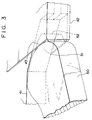
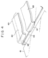
- FIGS. 3 and 4 are enlarged views of the distal end of the shutter opening lever in the loaded state and of the stopper.
- FIGS. 5 and 6 the same components are designated by the same numerals without duplicated description.
- a pivot 32 for axially and rotatably supporting the shutter opening lever 50 is secured to the carrier 30.
- a projecting portion 52 is formed at the distal end 51 of the shutter opening lever 50 to enter the aperture at the corner 43 of the shutter 42.
- the carrier 30 is provided with a stopper 60 welded or rivetted at the fixing portion 65.
- the stopper 60 has a bifurcated spring portion 63, 64, the distal ends of which are formed as claws 61, 62 for holding the left corner 44 of the shutter 42 in the loading state as described hereinafter.
- the pivot 32 and the stopper 60 are secured to the carrier 30.
- the distal end 51 of the shutter opening lever 50 firstly contacts with the right corner 43 of the shutter 42 and moves the shutter 42 toward the left corner 44.
- the claw 61 of the stopper 62 comes to catch the cartridge 41 against the bias force of the spring portion 64.
- the other claw 61 comes to catch the shutter 42, thereby reaching the fully loaded state shown by two-dot chain lines.
- the shutter 42 is securely held at the left and right corners 43, 44 by the distal end 51 of the shutter opening lever 50 and by the claws 61, 62.
- the claw 62 is formed at the distal end of the spring portion 64 slightly shorter than the other spring portion 63, and acts to absorb the dispersion of the stopping position of the left corner 44.
- the present invention has been applied to a FDD in which the carrier is guided to the unloaded and loaded positions by a cam provided in the frame and the sliding plate.
- a cam provided in the frame and the sliding plate.
- this invention it is also possible to use this invention in a FDD where a link mechanism is used instead of the cam.
- the shutter of the FD held open in the loaded state would not accidentally or easily close due to any undesirable external impacts, by inserting the projecting portion formed at the distal end of the shutter opening lever into the aperture existing in the shutter, or in addition thereto by holding the opposed corner of the shutter by claws formed at the distal end of the stopper.
- a shutter locking mechanism for a FDD capable of securely keeping the shutter in opened state against any external impact.
- This mechanism comprises a pivot secured to the carrier for axially and rotatably supporting the shutter opening lever, and a projecting portion formed at the distal end of the shutter opening lever and fit to an aperture existing at the shutter opening lever contact side of the shutter in the loading position.
- the projecting portion enters the aperture at the right corner of the shutter in the loaded position while at the left corner claw portions of the stopper hold the shutter for preventing the distal end of the shutter opening lever from separating from the shutter.
Landscapes
- Feeding And Guiding Record Carriers (AREA)
Applications Claiming Priority (2)
| Application Number | Priority Date | Filing Date | Title |
|---|---|---|---|
| JP14508/91U | 1991-02-22 | ||
| JP1991014508U JP2554576Y2 (ja) | 1991-02-22 | 1991-02-22 | カートリッジのシャッタ開閉装置 |
Publications (3)
| Publication Number | Publication Date |
|---|---|
| EP0500090A2 true EP0500090A2 (fr) | 1992-08-26 |
| EP0500090A3 EP0500090A3 (en) | 1992-09-30 |
| EP0500090B1 EP0500090B1 (fr) | 1996-06-12 |
Family
ID=11863014
Family Applications (1)
| Application Number | Title | Priority Date | Filing Date |
|---|---|---|---|
| EP92102821A Expired - Lifetime EP0500090B1 (fr) | 1991-02-22 | 1992-02-20 | Mécanisme de verrouillage de volet pour dispositif d'entraînement de disque souple |
Country Status (5)
| Country | Link |
|---|---|
| US (1) | US5299078A (fr) |
| EP (1) | EP0500090B1 (fr) |
| JP (1) | JP2554576Y2 (fr) |
| DE (1) | DE69211379T2 (fr) |
| HK (1) | HK22397A (fr) |
Families Citing this family (3)
| Publication number | Priority date | Publication date | Assignee | Title |
|---|---|---|---|---|
| JP2889470B2 (ja) * | 1993-10-07 | 1999-05-10 | アルプス電気株式会社 | 記録/再生装置 |
| US5488494A (en) * | 1993-10-07 | 1996-01-30 | Tamarack Storage Devices | Packaging system for holographic storage media |
| US6610126B2 (en) * | 2001-06-06 | 2003-08-26 | Donaldson Company, Inc. | Filter element having sealing members and methods |
Family Cites Families (9)
| Publication number | Priority date | Publication date | Assignee | Title |
|---|---|---|---|---|
| JPS5615063B2 (fr) * | 1973-02-09 | 1981-04-08 | ||
| CH655594B (fr) * | 1982-07-19 | 1986-04-30 | ||
| JPS62273652A (ja) * | 1986-05-21 | 1987-11-27 | Copal Co Ltd | デイスクカ−トリツジのシヤツタ開閉機構 |
| IT1203575B (it) * | 1986-06-20 | 1989-02-15 | Olivetti & Co Spa | Cartuccia per un disco ottico di registrazione di dati sulle due facce e relativo dispositivo di lettura |
| US4736356A (en) * | 1986-07-14 | 1988-04-05 | Optotech, Inc. | Optical disk drive |
| US4879616A (en) * | 1986-12-04 | 1989-11-07 | Fuji Photo Film Co., Ltd. | Magnetic disc pack loading mechanism |
| JPH01119952A (ja) * | 1987-10-31 | 1989-05-12 | Nakamichi Corp | ディスクカートリッジのシャッター開閉機構 |
| JPH03224166A (ja) * | 1989-07-05 | 1991-10-03 | Hitachi Maxell Ltd | ディスク駆動装置 |
| DE69033899T2 (de) * | 1989-07-05 | 2002-06-27 | Hitachi Maxell, Ltd. | Plattenkassette |
-
1991
- 1991-02-22 JP JP1991014508U patent/JP2554576Y2/ja not_active Expired - Lifetime
-
1992
- 1992-02-05 US US07/831,480 patent/US5299078A/en not_active Expired - Fee Related
- 1992-02-20 DE DE69211379T patent/DE69211379T2/de not_active Expired - Fee Related
- 1992-02-20 EP EP92102821A patent/EP0500090B1/fr not_active Expired - Lifetime
-
1997
- 1997-02-27 HK HK22397A patent/HK22397A/en not_active IP Right Cessation
Also Published As
| Publication number | Publication date |
|---|---|
| EP0500090A3 (en) | 1992-09-30 |
| JP2554576Y2 (ja) | 1997-11-17 |
| JPH04105870U (ja) | 1992-09-11 |
| HK22397A (en) | 1997-02-27 |
| EP0500090B1 (fr) | 1996-06-12 |
| US5299078A (en) | 1994-03-29 |
| DE69211379T2 (de) | 1996-12-12 |
| DE69211379D1 (de) | 1996-07-18 |
Similar Documents
| Publication | Publication Date | Title |
|---|---|---|
| EP0778567B1 (fr) | Cassette à disque | |
| US5657081A (en) | Electronic apparatus having a main body and loadable storage unit | |
| US5781232A (en) | Recording medium insertion and removal mechanism | |
| CN1003686B (zh) | 盒式磁盘装载装置 | |
| US5299078A (en) | Mechanism for locking a shutter of a floppy disk | |
| KR100306182B1 (ko) | 테이프카세트 | |
| JP3040919B2 (ja) | ビデオカセットレコーダーのカセット蓋予備開放装置 | |
| US4791515A (en) | Protecting a disc cartridge from inadvertent actuation during nonuse | |
| US6922839B2 (en) | Cartridge for protecting optical recording media | |
| US5249088A (en) | Cassette loading apparatus with resilient guide slot for prevention of jamming | |
| NL194284C (nl) | Cassettedetecteerinrichting voor cassettelaadmechanisme. | |
| EP0828249B1 (fr) | Boitier pour disque | |
| US20010005349A1 (en) | Loading device for optical disk medium | |
| KR0113722Y1 (ko) | 디스크 카트리지 수납장치 | |
| JPH0617230Y2 (ja) | 磁気ディスクカートリッジ | |
| JP2978324B2 (ja) | ディスク装置 | |
| EP0106726B1 (fr) | Mémoire à bulles du type cassette | |
| JPS61206984A (ja) | デイスクカ−トリツジ | |
| JPS6334148Y2 (fr) | ||
| KR940020347A (ko) | 전자기계 정보장치 데크 | |
| JPH0418092Y2 (fr) | ||
| JPS61246957A (ja) | 磁気デイスク装置 | |
| JPH07105672A (ja) | 電気機器におけるドアのロック機構 | |
| JPH0528612A (ja) | フロツピー・デイスク装置における媒体シヤツターの誤閉鎖防止装置 | |
| JPH07111016A (ja) | カートリッジローディング機構 |
Legal Events
| Date | Code | Title | Description |
|---|---|---|---|
| PUAI | Public reference made under article 153(3) epc to a published international application that has entered the european phase |
Free format text: ORIGINAL CODE: 0009012 |
|
| PUAL | Search report despatched |
Free format text: ORIGINAL CODE: 0009013 |
|
| AK | Designated contracting states |
Kind code of ref document: A2 Designated state(s): DE FR GB |
|
| AK | Designated contracting states |
Kind code of ref document: A3 Designated state(s): DE FR GB |
|
| 17P | Request for examination filed |
Effective date: 19920918 |
|
| 17Q | First examination report despatched |
Effective date: 19950511 |
|
| GRAH | Despatch of communication of intention to grant a patent |
Free format text: ORIGINAL CODE: EPIDOS IGRA |
|
| GRAA | (expected) grant |
Free format text: ORIGINAL CODE: 0009210 |
|
| AK | Designated contracting states |
Kind code of ref document: B1 Designated state(s): DE FR GB |
|
| REF | Corresponds to: |
Ref document number: 69211379 Country of ref document: DE Date of ref document: 19960718 |
|
| ET | Fr: translation filed | ||
| GRAH | Despatch of communication of intention to grant a patent |
Free format text: ORIGINAL CODE: EPIDOS IGRA |
|
| PLBE | No opposition filed within time limit |
Free format text: ORIGINAL CODE: 0009261 |
|
| STAA | Information on the status of an ep patent application or granted ep patent |
Free format text: STATUS: NO OPPOSITION FILED WITHIN TIME LIMIT |
|
| 26N | No opposition filed | ||
| PGFP | Annual fee paid to national office [announced via postgrant information from national office to epo] |
Ref country code: DE Payment date: 19991231 Year of fee payment: 9 |
|
| PGFP | Annual fee paid to national office [announced via postgrant information from national office to epo] |
Ref country code: FR Payment date: 20000210 Year of fee payment: 9 |
|
| PGFP | Annual fee paid to national office [announced via postgrant information from national office to epo] |
Ref country code: GB Payment date: 20000216 Year of fee payment: 9 |
|
| PG25 | Lapsed in a contracting state [announced via postgrant information from national office to epo] |
Ref country code: GB Free format text: LAPSE BECAUSE OF NON-PAYMENT OF DUE FEES Effective date: 20010220 |
|
| GBPC | Gb: european patent ceased through non-payment of renewal fee |
Effective date: 20010220 |
|
| PG25 | Lapsed in a contracting state [announced via postgrant information from national office to epo] |
Ref country code: FR Free format text: LAPSE BECAUSE OF NON-PAYMENT OF DUE FEES Effective date: 20011031 |
|
| REG | Reference to a national code |
Ref country code: FR Ref legal event code: ST |
|
| PG25 | Lapsed in a contracting state [announced via postgrant information from national office to epo] |
Ref country code: DE Free format text: LAPSE BECAUSE OF NON-PAYMENT OF DUE FEES Effective date: 20011201 |