EP0500135B2 - Brasage tendre à la vague dans une couverture avec atmosphère contrôlée sur un pot de métal d'apport de brasage tendre - Google Patents
Brasage tendre à la vague dans une couverture avec atmosphère contrôlée sur un pot de métal d'apport de brasage tendre Download PDFInfo
- Publication number
- EP0500135B2 EP0500135B2 EP92102979A EP92102979A EP0500135B2 EP 0500135 B2 EP0500135 B2 EP 0500135B2 EP 92102979 A EP92102979 A EP 92102979A EP 92102979 A EP92102979 A EP 92102979A EP 0500135 B2 EP0500135 B2 EP 0500135B2
- Authority
- EP
- European Patent Office
- Prior art keywords
- hood
- solder
- entrance
- exit
- gas
- Prior art date
- Legal status (The legal status is an assumption and is not a legal conclusion. Google has not performed a legal analysis and makes no representation as to the accuracy of the status listed.)
- Expired - Lifetime
Links
Images


Classifications
-
- H—ELECTRICITY
- H05—ELECTRIC TECHNIQUES NOT OTHERWISE PROVIDED FOR
- H05K—PRINTED CIRCUITS; CASINGS OR CONSTRUCTIONAL DETAILS OF ELECTRIC APPARATUS; MANUFACTURE OF ASSEMBLAGES OF ELECTRICAL COMPONENTS
- H05K3/00—Apparatus or processes for manufacturing printed circuits
- H05K3/30—Assembling printed circuits with electric components, e.g. with resistors
- H05K3/32—Assembling printed circuits with electric components, e.g. with resistors electrically connecting electric components or wires to printed circuits
- H05K3/34—Assembling printed circuits with electric components, e.g. with resistors electrically connecting electric components or wires to printed circuits by soldering
-
- B—PERFORMING OPERATIONS; TRANSPORTING
- B23—MACHINE TOOLS; METAL-WORKING NOT OTHERWISE PROVIDED FOR
- B23K—SOLDERING OR UNSOLDERING; WELDING; CLADDING OR PLATING BY SOLDERING OR WELDING; CUTTING BY APPLYING HEAT LOCALLY, e.g. FLAME CUTTING; WORKING BY LASER BEAM
- B23K1/00—Soldering, e.g. brazing, or unsoldering
- B23K1/08—Soldering by means of dipping in molten solder
- B23K1/085—Wave soldering
-
- B—PERFORMING OPERATIONS; TRANSPORTING
- B23—MACHINE TOOLS; METAL-WORKING NOT OTHERWISE PROVIDED FOR
- B23K—SOLDERING OR UNSOLDERING; WELDING; CLADDING OR PLATING BY SOLDERING OR WELDING; CUTTING BY APPLYING HEAT LOCALLY, e.g. FLAME CUTTING; WORKING BY LASER BEAM
- B23K35/00—Rods, electrodes, materials, or media, for use in soldering, welding, or cutting
- B23K35/22—Rods, electrodes, materials, or media, for use in soldering, welding, or cutting characterised by the composition or nature of the material
- B23K35/38—Selection of media, e.g. special atmospheres for surrounding the working area
-
- H—ELECTRICITY
- H05—ELECTRIC TECHNIQUES NOT OTHERWISE PROVIDED FOR
- H05K—PRINTED CIRCUITS; CASINGS OR CONSTRUCTIONAL DETAILS OF ELECTRIC APPARATUS; MANUFACTURE OF ASSEMBLAGES OF ELECTRICAL COMPONENTS
- H05K3/00—Apparatus or processes for manufacturing printed circuits
- H05K3/30—Assembling printed circuits with electric components, e.g. with resistors
- H05K3/32—Assembling printed circuits with electric components, e.g. with resistors electrically connecting electric components or wires to printed circuits
- H05K3/34—Assembling printed circuits with electric components, e.g. with resistors electrically connecting electric components or wires to printed circuits by soldering
- H05K3/3465—Application of solder
- H05K3/3468—Application of molten solder, e.g. dip soldering
-
- H—ELECTRICITY
- H05—ELECTRIC TECHNIQUES NOT OTHERWISE PROVIDED FOR
- H05K—PRINTED CIRCUITS; CASINGS OR CONSTRUCTIONAL DETAILS OF ELECTRIC APPARATUS; MANUFACTURE OF ASSEMBLAGES OF ELECTRICAL COMPONENTS
- H05K2203/00—Indexing scheme relating to apparatus or processes for manufacturing printed circuits covered by H05K3/00
- H05K2203/08—Treatments involving gases
- H05K2203/086—Using an inert gas
-
- H—ELECTRICITY
- H05—ELECTRIC TECHNIQUES NOT OTHERWISE PROVIDED FOR
- H05K—PRINTED CIRCUITS; CASINGS OR CONSTRUCTIONAL DETAILS OF ELECTRIC APPARATUS; MANUFACTURE OF ASSEMBLAGES OF ELECTRICAL COMPONENTS
- H05K3/00—Apparatus or processes for manufacturing printed circuits
- H05K3/30—Assembling printed circuits with electric components, e.g. with resistors
- H05K3/32—Assembling printed circuits with electric components, e.g. with resistors electrically connecting electric components or wires to printed circuits
- H05K3/34—Assembling printed circuits with electric components, e.g. with resistors electrically connecting electric components or wires to printed circuits by soldering
- H05K3/3489—Composition of fluxes; Application thereof; Other processes of activating the contact surfaces
-
- Y—GENERAL TAGGING OF NEW TECHNOLOGICAL DEVELOPMENTS; GENERAL TAGGING OF CROSS-SECTIONAL TECHNOLOGIES SPANNING OVER SEVERAL SECTIONS OF THE IPC; TECHNICAL SUBJECTS COVERED BY FORMER USPC CROSS-REFERENCE ART COLLECTIONS [XRACs] AND DIGESTS
- Y10—TECHNICAL SUBJECTS COVERED BY FORMER USPC
- Y10S—TECHNICAL SUBJECTS COVERED BY FORMER USPC CROSS-REFERENCE ART COLLECTIONS [XRACs] AND DIGESTS
- Y10S118/00—Coating apparatus
- Y10S118/07—Hoods
Definitions
- This invention pertains to a wave soldering machine and process for producing soldered connections on a printed circuit board carrying electronic components.
- Wave soldering is a common method of forming solder joints between electronic components and circuit traces on a printed circuit board.
- Electronic components are placed on a circuit board and their leads are inserted into holes in the circuit board so that the leads touch the metal pads to which they are to be soldered.
- the components may be glued to the circuit board to retain them during the soldering process.
- an applicator applies flux to the bottom of the board in the form of a spray, a foam or a wave.
- Flux allows soldering of metallic materials with poor wetability and solderability, such as oxidized copper. Flux also allows solder to fill metallized holes in the board more readily.
- the fluxed board is preheated to dry and activate the flux and to thermally prepare the board to contact the molten solder with low thermal stress.
- the activated flux reacts with metal oxides on the component leads and the circuit board pads and dissolves the oxides.
- the presence of oxygen as in air has been thought to be deleterious in the preheat operation since oxygen produces metal oxides.
- the bottom of the fluxed, preheated board is contacted with molten solder either in a static bath or in a pumped wave so as to wet the parts to be coated or joined with solder.
- molten solder either in a static bath or in a pumped wave so as to wet the parts to be coated or joined with solder.
- a coating of solder remains on the wetted parts.
- the adhering solder solidifies, forming electrically conductive joints and coatings.
- the board After soldering, the board is usually cleaned to remove the remaining flux and flux residues, which can cause corrosion, unwanted electrical conduction, poor appearance and interference with subsequent testing. Cleaning, however, is desirably eliminated since it is expensive and cleaning fluids are environmentally objectionable. Subsequent inspection or testing determines what connections, desired and undesired, have been made by the solder. The testing is usually performed by an array of pins brought into contact with the board pads and through which electrical measurements are made.
- soldering defects occur most frequently. A common defect is an incomplete or missing solder deposit where joining was intended, thereby causing an open. Another is bridging of solder between metalized portions on the board where joining was unintended, thereby causing a short. Still another is failure of the solder to fill a metallized hole in the board.
- a no-clean flux is a flux that after solder contact leaves a low level of residue which is noncorrosive and nonconductive.
- a no-dean flux contains little or no halide, but most preferably a non-corrosive, non-conductive organic acid dissolved in a solvent such as ethanol or isopropanol.
- Common RMA flux is a no-clean flux consisting of a mixture of rosin (abietic acid), activator (dimethylamine hydrochloride) and solvent (alcohol).
- Another no-clean flux is adipic acid (1% by weight) in ethyl or isopropyl alcohol.
- no-clean flux desirably is applied in a thin layer.
- the following table shows the relationship between the thickness of an RMA flux layer and observed air atmosphere soldering and test contact defects. The data are from Soldering In Electronics by Wassink and Klein, 1984, page 235. Flux Thickness, microns Contact Defects, per million joints Soldering Defects, Type 15 3,333 4 333 bridging 2 50 bridging, poor hole filling
- Conventional wave soldering machines which apply flux to a circuit board, preheat the board, contact the board with a molten wave of solder and then detach the board from the solder wave.
- the board is transported sequentially by a conveyer through these operations, which are performed in air.
- the machine configuration comprises a fluxer, preheater and solder pot and conveyer mounted on a frame and enclosed by a liftable cover on a hinge. A slight vacuum is applied at a port at a central point in the cover to draw off objectional fumes emanating from these operations.
- wave soldering machines have been designed to flux, preheat and solder circuit boards in an inert or protective amosphere. These machines provide benefits over machines which perform these operations in air as follows:
- a protective atmosphere under which wave soldering is performed with the benefits mentioned comprises a non-oxidizing gas and not more than 5 percent oxygen, preferably not more than 100 ppm oxygen, and most preferably not more than 10 ppm oxygen.
- Nitrogen is a satisfactory non-oxidizing gas in which to perform the contacting with solder, and because of its low cost, nitrogen is a preferred non-oxidizing gas.
- the various operations are conducted in a long continuous enclosure or series of joined tunnels.
- Typical apparatus is described in US-A-4 921 156.
- the protective atmosphere is introduced into the tunnel enclosing the solder pot and flows out through the work entrance tunnel and the work egress tunnel.
- seal flaps are provided in the tunnels. The flaps are tilted open in the transport direction by a passing workpiece and close thereafter. Thus fluxing, preheating, solder attachment, detachment, and cooling are under a protective atmosphere.
- JP-A-61-82965 discloses a wave soldering machine in which molten solder is contained in a solder bath containing a nozzle through which the molten solder is discharged by the operation of an impeller located within the solder bath. A hood is installed in an airtight manner on top of the outside wall of the solder bath.
- US-A-4 610 391 describes a process for wave soldering a work piece in an atmosphere consisting essentially of air wherein there is a first portion of the solder wave, said first portion including dross forming area, and wherein there is a second portion of the solder wave, which is the last portion of the solder wave with which the work-piece comes into contact.
- the atmosphere in contact with at least 50 % of the surface of the dross forming area is replaced with an inert gas while the atmosphere in contact with the second portion is prevented from becoming inert.
- a wave soldering apparatus comprising a solder pot and enclosure means for containing a protective atmosphere during contacting of circuit boards with a solder wave in the pot, said enclosure means having an entrance for circuit boards on an entrance side and an exit for circuit boards on an exit side a supply of non-oxidizing gas having an oxygen content not greater than 5% by volume, and means for admitting said cas into said enclosure means, is known from US-A-4 538 757.
- gas jets have been used to form gas curtains and provide gas flow barriers at specific locations in tunnels.
- An alternative to a new soldering machine designed to solder in a protective atmosphere is to retrofit an existing machine so that it can be operated in a protective atmosphere.
- wave soldering machines initially designed to solder printed circuit boards under a protective atmosphere have provided a protective atmosphere for all the functions of fluxing, preheating, contacting with solder, separation from solder and cooling of the board. It has bean believed that a protective atmosphere for all these functions was necessary to achieve the benefits of soldering in a protective atmosphere as enumerated earlier.
- to provide a protective atmosphere for all these sections of a conventional air soldering machine is significant in terms of cost, additional complexity and retrofit time.
- the invention provides a wave soldering apparatus as defined in claim 1.
- the protective atmosphere may be generated by separation of air by membrane or pressure swing adsorption, or by partial combustion of air.
- the wave soldering apparatus of the present invention is provided with a hood to enclose and provide a protective atmosphere over the solder wave in the solder pot of a wave soldering machine while leaving the other operative areas exposed to a non-protective atmosphere.
- non-protective atmosphere is meant any gas mixture having an oxygen concentration of, or oxidizing capability equivalent to, 5 volume percent or greater, an example being air.
- the hood has an opening for an inlet on one side and an opening for an outlet on another side for the passage of a circuit board conveyer over the solder wave.
- a short duct extending from a hood side may be provided for a hood inlet or outlet.
- the lower extremity of the hood fits around and is sealed on three sides to the upper extremity of the solder pot by an elastomeric seal.
- the remaining side of the hood carries an elastomeric seal and butts up against an upright bulkhead having its lower extremity immersed in the solder and sealed to the inside walls of the solder pot.
- the elevation of the pot is adjustable while the sealing is maintained. Also the pot and its bulkhead may be withdrawn laterally from under the hood.
- Air is restricted from entering the inlet and outlet openings of the hood by curtains of thin solid material cut into vertical strips.
- the curtain material is electrically conductive to avoid the build up of static charge by rubbing on a circuit board as it passes through the curtain.
- Protective atmosphere is introduced by one or more distributors under the hood.
- a preferred embodiment uses three gas distributors. One distributor is located directly over the solder wave and over the path of the conveyer. Another distributor is located on the forward side of the solder wave under the path of the conveyer. The third gas distributor is located on the rearward side of the solder wave under the path of the conveyer.
- the distributors are porous tubes of sintered metal allowing the protective gas to be introduced in a laminar flow.
- a cover Around the pump shaft which produces the solder wave is a cover with its lower extremity extending into the solder in the pot to form a seal.
- collector ducts Outside the hood, over the inlet opening and the outlet opening are collector ducts for collecting the exhaust gas emanating from the hood through these openings.
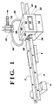
- the machine comprises a frame (not shown) on which is mounted a conveyer 2 for transporting printed circuit boards 4. After being loaded with a circuit board, the conveyer carries the circuit board through a flux applicator 6 which is in an ambient air atmosphere.
- Flux for use in this invention is no-clean flux.
- a preferred no-clean flux is 1% by weight of adipic acid dissolved in ethanol or isopropanol.
- the flux is applied to the bottom of the board by common techniques to provide after the evaporation of solvents a layer with a thickness of 4 microns or less, preferably 2 microns or less.
- the use of a flux allows soldering materials with poor wetability and solderability, such as oxidized copper, and allows good filling with solder of plated or metallized holes in the circuit board. With the thin layer of no-clean flux used in this invention, cleaning of boards after soldering is unnecessary in most cases.
- the conveyer 2 next passes the circuit board over a preheater 8 where the board is heated in an air atmosphere to a temperature between 70°C and the melting point of the solder used. Typically the preheat temperature is 100°C to 160°C. The flux solvent is evaporated upon reaching 70°C in the preheater.
- solder pot 10 Next on the machine frame in the line of travel of the conveyer is an open solder pot 10 or tank While the process is not limited to a given solder composition, a solder alloy typically used is 62.5% tin, 37% lead and 0.5% antimony by weight. Solder bath temperatures range typically between 190 and 300°C, most typically between 240°C to 260°C.
- the solder pot 10 has a generally rectangular or "L" shape when viewed from above.
- the pot contains molten solder 12, a means 14 for pumping the solder into a wave and a wave flow guide 16.
- the pumping means 14 comprises a shaft 18 partially immersed in the solder.
- the immersed portion of the shaft has an impeller 20 for pumping the molten solder.
- the unimmersed upper portion of the shaft is driven by a motor or by a belt.
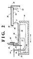
- the shaft is provided with an inverted cup-shaped cover 22.
- the lower, open portion of the cup is immersed in the solder to provide a seal.
- An inlet 24 is provided for a protective atmosphere to be supplied under or into the cover 22.
- a small hole is also provided in the cover for the supplied gas to vent.
- An alternate solder pumping means is a magneto-hydrodynamic pump (not shown).
- a vertical bulkhead 26 located towards the rear of the solder pot has its lower edge immersed into the solder.
- the bulkhead side edges which extend into the solder pot are sealed by an elastomeric material to the inside walls of the solder pot.
- the bulkhead has a vertical front extension 28.
- the hood has a first or front side 32 facing where an operator usually would stand, a second or entrance side 34 facing the advancing conveyer, a third or exit side 36 facing the retreating conveyer and a fourth or rear side 38 opposite the front side 32.
- the entrance side 34 of the hood On the entrance side 34 of the hood is an opening 40 for an entrance, and on the opposite or exit side 36 of the hood is an opening 42 for an exit.
- the conveyer for transporting circuit boards passes in an upward inclination through the entrance in the hood, over the solder wave and emerges through the exit in the hood.
- the entrance and/or exit for the boards may include a short duct (not shown) extending from the hood side.
- the rear side 38 of the hood carries an elastomeric seal 46 and butts against the front vertical extension 28 of the bulkhead 26.
- the solder pot with the bulkhead is movable vertically without breaking the seals to adjust the elevation of the pot.
- the solder pot also can be withdrawn rearwards from under the hood to facilitate maintenance.
- the top of the hood has a polycarbonate window 48 for viewing of the solder wave.
- One edge of the window is attached to a hinge allowing the window to be opened. Edges of the window when closed are sealed by an elastomeric gasket.
- the front side 32 of the hood also has a polycarbonate window 50 for viewing of the depth of solder contact by the circuit boards into the solder wave as they pass across the wave.
- Polycarbonate window material is selected for its lightness, nonbreakability and machinability. The latter property allows the polycarbonate to be drilled to provide holes for attachment to supporting structure.
- a protective atmosphere is comprised of a non-oxidizing gas and not more than 5% oxygen by volume, preferably not more than 100 ppm oxygen and most preferably not more than 10 ppm oxygen.
- the non-oxidizing gas must have an oxygen content not greater than the oxygen level desired in the protective atmosphere.
- the non-oxidizing gas has not more than one-half the oxygen concentration desired in the protective atmosphere.
- Nitrogen is a preferred non-oxidizing gas because of its low cost and availability.
- gases also useful for this purpose are carbon dioxide, argon, water vapor, hydrogen and other non-oxidizing gases and mixtures thereof.
- gaseous formic acid or other reactive gas i.e., other gaseous mono-carboxylic acid
- the protective gas may be supplied with, or introduced into, the protective gas in concentrations of 10 ppm to 10% by volume, preferably 100 ppm to 1%, and most preferably 500 ppm to 5,000 ppm..
- the added reactive gas removes oxides which may not have been removed by the flux from the metalized portions of the board or the component leads. Additionally, such reactive gases allow a higher oxygen content in the protective atmosphere without deleterious effects.
- the detachment of the board from the solder is in a controlled atmosphere. Usually the detachment is performed in the same atmosphere as the attachment. However in some circumstances, such as to reduce undesired solder connections (bridging), the oxygen content may desirably be higher in the detachment region than in the attachment region.
- Gas, to provide the desired atmosphere is preferably introduced under the hood through distributors in one, two or preferably three locations.
- the distributors are porous, sintered metal tubes having a diameter of 10 mm and a length approximately equal to the length of the hood inlet and outlet openings. They have a pore size of about 0.0005 mm to 0.05 mm, preferably 0.002 to 0.005 mm.
- Each distributor extends horizontally normal to the direction of travel of the conveyer 2.
- the first distributor 52 in the direction of travel of a circuit board is located below the conveyer in front of the solder wave.
- the second distributor 54 is located over the conveyer over the solder wave.
- the third distributor 56 is located below the conveyer after the solder wave.
- the two lower distributors 52, 56 are each cantilevered in a horizontal attitude from respective vertical gas supply tubes which enter through and are supported from the top of the bulkhead 26 and extend horizontally under the bulkhead extension 28.
- the depth of penetration of each gas supply tube is adjustable allowing each lower distributor to be positioned below the top edge of the solder pot and close to the solder surface.
- the upper distributor 54 is supported in a horizontal attitude by a gas supply tube entering the top of the hood.
- the hood With the hood enclosing only the solder pot, the hood is so short that the leading portion of a circuit board may contact the solder wave while the trailing portion protrudes from the entrance opening.
- the first and second gas distributers 52, 54 mainly supply gases providing the atmosphere for the bottom and top of an entering board and attaching to the wave.
- the leading portion of a board may protrude out of the exit opening while its trailing portion is in the solder wave.
- the second and third distributors 54, 56 mainly supply gases providing the atmosphere for the top and bottom of a leaving board and detaching from the wave. This configuration allows different oxygen concentrations to be achieved during attachment to the molten solder and during detachment from the solder.
- oxygen concentration in the detachment region can be established independently at an optimum level to obtain a minimum bridging rate for a given flux composition and flux layer thickness.
- RMA flux 3 microns thick yields low bridging rates with oxygen concentrations of 5 to 21%.
- solder surfaces forming the wave are susceptible to entrainment of hood gas as minute bubbles.
- the bubbles rise to the surface of the solder and burst releasing minute fragments of solder into the protective atmosphere.
- These fragments form minute spheres or balls, in the order of 0.2 to 0.5 mm in diameter, that travel throughout the atmosphere under the hood and deposit on all exposed surfaces. Periodic brushing removes the balls.
- Downward solder flows from the wave are provided with a guide or chute to reduce entrainment of gas into the solder.
- gas is supplied at a limited rate to issue from the distributors in a laminar flow.
- Laminar flow is considered to exist when the root mean square of random fluctuations in fluid velocity, as measured for example by a hot wire anemometer, do not exceed 10% of the average velocity. This criterion is desirably met not only by the flow emanating from the gas distributors, but throughout the entire hood space.
- the laminar flow provides a quiescent atmosphere which minimizes the entrainment of gas into the flowing solder surfaces and the infiltration of air through the hood openings.
- a lower density gas may be supplied from the upper distributor (above the conveyer), and a higher density gas from the lower distributors (below the conveyer).
- the higher density gas will occupy the hood space mostly below the conveyer and the lower density gas the hood space mostly above the conveyer.
- the inlet and outlet openings 40, 42 to the hood are preferably rectangular and are provided with curtains 58 of a solid material to restrict air from entering the hood.
- the curtains are a thin, flexible material cut into vertical strips to minimize the drag forces exerted on the electrical components as they enter and exit through these openings. Preferred thicknesses range from 0.1 to 0.2 mm. Overly thin curtains are blown open by the exhaust flow. Overly thick curtains displace components from desired positions on the circuit board.
- the curtain material is electrically conductive and electrically grounded.
- a static charge may destroy the functionality of electrical components on the board.
- the curtains do not shed fibers onto the circuit board, are resistant to chemical attack by the flux and solder fumes, are tolerant of temperatures to 265°C and withstand physical brushing to remove the minute solder balls which deposit in the enclosed soldering environment.
- a suitable material is silicone rubber loaded with graphite fibers.
- a circuit board detaches from the solder wave in a protective atmosphere and immediately begins to cool. Because of the shortness of the hood, a board leaving the wave quickly emerges from the exit opening in the hood and cools in air.
- a preferred embodiment includes an exhaust gas collector over the inlet opening to the hood and an exhaust gas collector over the outlet opening of the hood.
- the gas exhausting from the hood is preferably not allowed to escape into the solder machine environment, since, in most instances, it has insufficient oxygen for respiration and contains noxious flux fumes.
- a collector is a U-shaped duct with bits opening facing the hood opening.
- a collector may comprise a tube with perforations facing the hood opening.
- Each collector leads to its own closed exhaust duct 64, 66 to carry away the collected exhaust gases.
- collectors are additionally or exclusively provided along the bottoms of the hood openings.
- each exhaust duct is a valve 68, 70 to control the amount of exhaust gas which is collected by its corresponding collector.
- the valves in the closed ducts leading from the collectors the exhaust flow captured by each collector may be controlled.
- the adjustment of the valves in the exhaust ducts may be used also to counter a pressure distribution created outside one or both of the openings in the hood. Such a pressure distribution may be a draft created by a fan which may blow on, across, or away from one of the openings.
- a soldering machine originally designed with fluxer, preheater and solder pot to operate in air usually has a liftable cover over these components.
- the cover usually is provided with at least one exhaust port maintained at a slight vacuum to draw off noxious fumes generated in these operations.
- exhaust collectors over the hood openings are desirable to remove the gas emanating therefrom.
- the exhaust in the machine cover often does not have sufficient capacity and is not appropriately located to withdraw the gas discharges from the hood.
- the preferred embodiment includes several safety features.
- a safety shut-off valve operated by a solenoid is provided in the protective gas supply line. This shut-off valve is maintained closed under two conditions. One is when a contact switch senses that the top window on the hood is open. Another is when a differential pressure sensor determines that the pressure in the exhaust ducts is atmospheric and thus that no exhaust is being collected.
- the solder pump is controlled so that it cannot operate unless the supplied gas shut-off valve is open and protective gas is flowing into the hood.
- a hood configured pursuant to this invention, having inlet and exit openings 40.7 cm wide by 10.2 cm high obscured with strip curtains through which circuit boards were conveyed, 11 normal cubic centimeters per second of nitrogen (having not more than 10 ppm of oxygen) per square centimeter of hood opening distributed under the hood maintained oxygen concentration in the hood at 100 ppm.
- a normal volume of gas as used herein denotes an amount of gas equal to the volume of the gas at 25°C and 1 atmosphere. Benefits of protective atmosphere soldering are achievable in hoods configured pursuant to this invention with non-oxidizing gas consumptions ranging from 5 to 50 normal cubic centimeters per second per square centimeter of hood opening.
- a hood was fabricated and operated in accordance with this invention.
- the hood had entrance and exit openings each 40.7 cm wide by 10.2 cm high.
- the hood was purged with nitrogen with an oxygen content of about 1 ppm.
- the nitrogen was initially at room temperature and the solder wave was at 260°C.
- the oxygen level over the solder wave was measured versus nitrogen flow rate for different levels of uncurtained opening height.
- Uncurtained opening height is the distance from the bottom of the curtains to the bottom of an entrance or exit opening. The openings often have a significant uncurtained height in order to prevent the jostling of tall unstable parts.
- An advantage of this invention is that low oxygen levels can be obtained even with relatively large uncurtained opening heights.
- circuit boards with tall unstable parts can be processed without resorting to mechanical doors which must open and shut to prevent air infiltration.
- Fig. 4 shows the oxygen levels observed versus supplied gas flow per unit area of uncurtained opening for 3 different uncurtained heights, 10.2 cm, 7.6 cm, and 5.1 cm. The uncurtained heights were the same for the entrance and exit openings.
- Required gas flow is the total nitrogen flow in normal cubic centimeters per second.
- A is a parameter that varies between 40 and 60. The units for “A” are normal cubic centimeters per second per square centimeter.
- B is the total uncurtained area in square centimeters.
- Ppm O 2 is the difference between the maximum oxygen level desired at the solder wave and the oxygen content of the supplied gas.
- C is the nitrogen flow required when the uncurtained area is zero. "C” is about 2,000 normal cubic centimeters per second for reasonably tight hoods.
- E is an empirical parameter. For nitrogen and gases with a density within 10% of nitrogen, “E” has a value between 5 and 50 cm 3 /sec/cm 2 . “E” preferably is in the range of 8 to 20 cm 3 /sec/cm 2 . “Total opening area” is the sum of the curtained and uncurtained area of both the entrance and exit and any other opening.
- Low density gases such as hydrogen will have larger values for "E”.
- High density gases such as carbon dioxide and argon will have lower values by about one-half for the parameter "E".
- F is an empirical parameter. For nitrogen and gases with a density within 10% of nitrogen, “F” has a value between 4,000 and 40,000 cm 3 /sec. “F” preferably is in the range of 7,000 to 16,000 cm 3 /sec.
- Low density gases such as hydrogen will have larger values of "F”.
- High densify gases such as carbon dioxide and argon will have lower values by about one-half for "F".
- Circuit boards with 120 closely spaced potential bridging sites were fluxed with a spray fluxer.
- the applied flux was Hi-Grade 784 manufactured by Hi-Grade Alloy Corp, East Hazelcrest, IL.
- Hi-Grade 784 is an RMA flux which leaves noncorrosive and nonconductive residues.
- the amount of flux applied to the circuit boards was controlled by varying the duration of the spray.
- the thickness of the flux was calculated from the weight of the flux deposited on the circuit board and the density of the flux (0.8 gm/cc).
- the circuit boards were then passed over a preheater which heated them to about 70°C in the air.
- the boards then entered a solder pot hood with a general configuration as described earlier.
- the hood had inlet and exit openings 40.7 cm long by 10.3 cm high.
- Extending normally from each hood opening for 25 cm and integral with the hood was a sheet metal duct with cross-section identical to the opening.
- At the end of each duct completely covering its opening was a curtain of the type previously described.
- the top of the hood had a polycarbonate window above the solder wave for viewing the wave.
- the window did not soften or sag. Its outside temperature was about 60°C.
- the instant apparatus using modest thicknesses of no-clean flux, allows wave soldering with minimal rates of soldering and contact defects, elimination of cleaning, moderate consumption of protective atmsophere gas and low apparatus cost.
Landscapes
- Engineering & Computer Science (AREA)
- Mechanical Engineering (AREA)
- Manufacturing & Machinery (AREA)
- Microelectronics & Electronic Packaging (AREA)
- Electric Connection Of Electric Components To Printed Circuits (AREA)
- Molten Solder (AREA)
- Shielding Devices Or Components To Electric Or Magnetic Fields (AREA)
- Gas-Insulated Switchgears (AREA)
Claims (9)
- Dispositif de brasage tendre à la vague comprenant un pot de métal d'apport de brasage tendre (10) et des moyens de confinement (26, 30) pour contenir une atmosphère protectrice durant le contact de plaquettes à circuits imprimés avec une vague de métal d'apport de brasage tendre (12) dans le pot, lesdits moyens de confinement ayant une entrée (40) pour les plaquettes à circuits imprimés sur une face d'entrée (34) et une sortie (42) pour les plaquettes à circuits imprimés sur une face de sortie (36), une alimentation en gaz non oxydant ayant une teneur en oxygène non supérieure à 5 % en volume, et des moyens (52, 54, 56) pour l'admission desdits gaz dans lesdits moyens de confinement ;
dans lequel lesdits moyens de confinement (26, 30) comprennent une cloison (26) et une couverture (30) ;
dans lequel ladite cloison (26) est fixée au pot de métal d'apport de brasage tendre (10), l'extrémité inférieure de la cloison (26) est immergée dans le métal d'apport de brasage tendre (12) contenu dans le pot de métal d'apport de brasage tendre (10) ;
dans lequel la couverture (30) est placée à l'extrémité supérieure du pot de métal d'apport de brasage tendre (10), la couverture (30) forme une enceinte sur pas plus que le pot de métal d'apport de brasage tendre et définit lesdites faces d'entrée et de sortie (34, 36), et les extrémités inférieures d'une face avant (32), de la face d'entrée (34) et de la face de sortie (36) de la couverture (30) sont configurées pour s'ajuster autour de l'extrémité supérieure de la face extérieure du pot de métal d'apport de brasage tendre (10) ;
dans lequel des moyens (44, 46) pour sceller la couverture (30) au pot de métal d'apport de brasage tendre (10) sont fournis, lesdits moyens de scellement (44, 46) comprenant un premier joint élastomère (44) sur les faces internes des extrémités inférieures des faces avant, d'entrée et de sortie (32, 34, 36) de la couverture (30), ledit premier joint élastomère (44) étant destiné à entrer en contact avec les surfaces supérieures externes du pot de métal d'apport de brasage tendre (10), et un second joint élastomère (46) sur la surface externe d'une face arrière (38) de la couverture (30) étant destiné à entrer en contact avec la cloison (26) ;
dans lequel le pot de métal d'apport de brasage tendre (10) avec la cloison (26) est conçu pour être retiré latéralement d'en dessous de la couverture (30) ; et
dans lequel le pot de métal d'apport de brasage tendre (10) avec la cloison (26) est conçu pour se déplacer verticalement sans rompre les joints obtenus par lesdits moyens de scellement (44, 46). - Dispositif selon la revendication 1, comprenant de plus un rideau (58) en matériau solide fin coupé en bandes verticales pour réduire l'entrée d'air atmosphérique par une au moins de ladite entrée (40) et ladite sortie (42).
- Dispositif selon la revendication 2, dans lequel ledit matériau du rideau sur ladite entrée (40) est électriquement conducteur et connecté à la masse.
- Dispositif selon la revendication 2 ou 3, dans lequel ledit matériau du rideau a une épaisseur comprise entre 0,1 et 0,2 mm.
- Dispositif selon l'une quelconque des revendications 2 à 4, dans lequel ledit rideau (58) est formé de caoutchouc silicone chargé avec des fibres de graphite.
- Dispositif selon l'une quelconque des revendications 2 à 5, dans lequel ledit matériau du rideau est flexible.
- Dispositif selon la revendication 1, dans lequel au moins une desdites entrée et sortie (40, 42) comprend de plus un conduit (64, 66) ayant une première extrémité couvrant une ouverture dans ladite face d'entrée ou de sortie (34, 36), ledit conduit s'étendant du côté de la couverture à une seconde extrémité pour le passage des plaquettes à circuits imprimés (4).
- Dispositif selon la revendication 1, dans lequel ladite couverture (30) comprend un conduit collecteur d'échappement (64) avec un collecteur (60) attenant à ladite entrée et un conduit collecteur d'échappement (66) avec un collecteur (62) attenant à ladite sortie de façon à collecter les gaz d'échappement émanant de ladite couverture à travers lesdites entrée et sortie et empêcher leur échappement dans l'environnement de la couverture, chaque conduit collecteur d'échappement ayant des moyens (68, 70) pour le contrôle du débit, par lesquels la distribution de l'échappement de gaz à travers ladite entrée et à travers ladite sortie peut être contrôlée.
- Dispositif selon la revendication 1, dans lequel lesdits moyens (52, 54, 56) pour l'admission de gaz dans ladite couverture (30) comprennent un distributeur de gaz (52, 56) en porte-à-faux en position horizontale à partir d'un tube d'alimentation en gaz vertical supporté par une cloison (26) fixée au pot de métal d'apport de brasage tendre.
Applications Claiming Priority (2)
| Application Number | Priority Date | Filing Date | Title |
|---|---|---|---|
| US660415 | 1991-02-22 | ||
| US07/660,415 US5176307A (en) | 1991-02-22 | 1991-02-22 | Wave soldering in a protective atmosphere enclosure over a solder pot |
Publications (4)
| Publication Number | Publication Date |
|---|---|
| EP0500135A2 EP0500135A2 (fr) | 1992-08-26 |
| EP0500135A3 EP0500135A3 (en) | 1993-01-07 |
| EP0500135B1 EP0500135B1 (fr) | 1996-04-10 |
| EP0500135B2 true EP0500135B2 (fr) | 2002-10-23 |
Family
ID=24649455
Family Applications (1)
| Application Number | Title | Priority Date | Filing Date |
|---|---|---|---|
| EP92102979A Expired - Lifetime EP0500135B2 (fr) | 1991-02-22 | 1992-02-21 | Brasage tendre à la vague dans une couverture avec atmosphère contrôlée sur un pot de métal d'apport de brasage tendre |
Country Status (10)
| Country | Link |
|---|---|
| US (1) | US5176307A (fr) |
| EP (1) | EP0500135B2 (fr) |
| JP (1) | JPH0577038A (fr) |
| KR (1) | KR0139096B1 (fr) |
| CN (1) | CN1037227C (fr) |
| BR (1) | BR9200581A (fr) |
| CA (1) | CA2061646C (fr) |
| DE (1) | DE69209693T3 (fr) |
| ES (1) | ES2085504T5 (fr) |
| MX (1) | MX9200746A (fr) |
Families Citing this family (47)
| Publication number | Priority date | Publication date | Assignee | Title |
|---|---|---|---|---|
| US5292055A (en) * | 1991-12-06 | 1994-03-08 | Electrovert Ltd. | Gas shrouded wave improvement |
| US5397049A (en) * | 1991-12-06 | 1995-03-14 | Electrovert Ltd. | Gas shrouded solder wave with reduced solder splatter |
| US5333776A (en) * | 1993-09-30 | 1994-08-02 | Air Products And Chemicals, Inc. | Atmospheres for brazing aluminum and aluminum alloys |
| NL9301935A (nl) * | 1993-11-08 | 1995-06-01 | Soltec Bv | Soldeermachine met aangepaste soldeertoren. |
| JPH07212028A (ja) * | 1994-01-13 | 1995-08-11 | Matsushita Electric Ind Co Ltd | リフロー装置 |
| JP3120695B2 (ja) * | 1995-05-19 | 2000-12-25 | 株式会社日立製作所 | 電子回路の製造方法 |
| DE19749184B4 (de) * | 1997-11-07 | 2007-03-01 | Air Liquide Deutschland Gmbh | Lötvorrichtung |
| DE19749186A1 (de) * | 1997-11-07 | 1999-06-10 | Messer Griesheim Gmbh | Anordnung einer Ummantelung zur Aufnahme einer Schutzgasatmosphäre zum Löten von Flachbaugruppen |
| DE19749185A1 (de) * | 1997-11-07 | 1999-05-12 | Messer Griesheim Gmbh | Mit einer Gasversorgung verbindbare Gasverteilung |
| US6168065B1 (en) * | 1998-02-17 | 2001-01-02 | Soltec B.V. | Movable selective debridging apparatus for debridging soldered joints on printed circuit boards |
| DE19903957B4 (de) * | 1999-01-25 | 2008-05-21 | Finetech Gmbh & Co.Kg | Verfahren und Vorrichtung zum Entfernen von Lot |
| CA2364248C (fr) * | 1999-03-08 | 2006-08-29 | David A. Tomkins | Fixation amelioree d'elements piezo-electriques |
| DE19912718C1 (de) * | 1999-03-20 | 2000-02-03 | Messer Griesheim Gmbh | Lötvorrichtung |
| US6367677B1 (en) | 1999-09-28 | 2002-04-09 | Hill-Rom Services, Inc. | Wave solder apparatus and method |
| DE10024458B4 (de) * | 2000-05-18 | 2005-08-18 | Air Liquide Deutschland Gmbh | Lötvorrichtung und Verfahren zum Löten von Flachbaugruppen |
| TW570856B (en) * | 2001-01-18 | 2004-01-11 | Fujitsu Ltd | Solder jointing system, solder jointing method, semiconductor device manufacturing method, and semiconductor device manufacturing system |
| DE10125552C2 (de) * | 2001-05-23 | 2003-05-28 | Messer Griesheim Gmbh | Lötvorrichtung zum Löten von Flachbaugruppen |
| JP2003290913A (ja) * | 2002-03-29 | 2003-10-14 | Tohoku Tsushin Kk | 局部半田付け装置の噴流ノズル構造 |
| CN100482043C (zh) | 2004-04-16 | 2009-04-22 | P.凯金属股份有限公司 | 焊接方法 |
| GB0411666D0 (en) * | 2004-05-25 | 2004-06-30 | Pillarhouse Int Ltd | Pump arrangement in a selective soldering apparatus |
| US7918383B2 (en) * | 2004-09-01 | 2011-04-05 | Micron Technology, Inc. | Methods for placing substrates in contact with molten solder |
| TW200610122A (en) * | 2004-09-14 | 2006-03-16 | P Kay Metal Inc | Soldering process |
| DE102005046563B3 (de) * | 2005-09-28 | 2007-02-08 | Messer Group Gmbh | Lötvorrichtung zum Löten von Flachbaugruppen |
| DE102005052076B4 (de) * | 2005-10-28 | 2007-09-20 | Messer Group Gmbh | Lötvorrichtung mit Gasverteilung |
| JP3942623B2 (ja) * | 2005-12-12 | 2007-07-11 | 富士通テン株式会社 | フラットディップ装置およびフラットディップ装置のはんだ付け方法 |
| DE102006024192A1 (de) * | 2006-05-23 | 2007-11-29 | Linde Ag | Vorrichtung und Verfahren zum Wellenlöten |
| DE502007006711D1 (de) * | 2006-05-23 | 2011-04-28 | Linde Ag | Vorrichtung und Verfahren zum Wellenlöten |
| JP2007073994A (ja) * | 2006-12-01 | 2007-03-22 | Nihon Dennetsu Keiki Co Ltd | 水蒸気雰囲気によるプリント配線板のはんだ付け方法 |
| DE102007002777A1 (de) * | 2007-01-18 | 2008-07-24 | Linde Ag | Vorrichtung und Verfahren zum Selektivlöten |
| US8104662B2 (en) * | 2009-07-24 | 2012-01-31 | Flextronics Ap Llc | Inert environment enclosure |
| US20110139855A1 (en) * | 2009-12-16 | 2011-06-16 | Ristolainen Tero | Residual oxygen measurement and control in wave soldering process |
| US8220699B2 (en) | 2010-03-12 | 2012-07-17 | Air Products And Chemicals, Inc. | Apparatus and method for providing an inerting gas during soldering |
| TWI401131B (zh) * | 2010-03-12 | 2013-07-11 | Air Prod & Chem | 於軟焊時提供惰性化氣體的設備及方法 |
| US8579182B2 (en) * | 2011-06-17 | 2013-11-12 | Air Products And Chemicals, Inc. | Method for providing an inerting gas during soldering |
| CN102601478B (zh) * | 2012-03-15 | 2014-10-22 | 哈尔滨工业大学 | 针灸用不锈钢管与内部铜丝的钎焊方法 |
| US9198300B2 (en) | 2014-01-23 | 2015-11-24 | Illinois Tool Works Inc. | Flux management system and method for a wave solder machine |
| US9161459B2 (en) * | 2014-02-25 | 2015-10-13 | Illinois Tool Works Inc. | Pre-heater latch and seal mechanism for wave solder machine and related method |
| DE102014018165B3 (de) * | 2014-12-09 | 2016-01-07 | Messer Austria Gmbh | Lötvorrichtung mit Gasverteilung |
| JP6666071B2 (ja) * | 2015-04-03 | 2020-03-13 | セイテック株式会社 | 局所半田付け方法 |
| DE102015212960B4 (de) * | 2015-07-10 | 2019-01-31 | Robert Bosch Gmbh | Verfahren zum Betreiben einer Pumpe |
| CN104999150A (zh) * | 2015-07-15 | 2015-10-28 | 深圳市创荣发电子有限公司 | 一种波峰焊锡炉的节能装置及其节能方法 |
| CN106881517A (zh) * | 2017-03-30 | 2017-06-23 | 北京康普锡威科技有限公司 | 二氧化碳气体保护的电子产品焊接方法 |
| JP7249215B2 (ja) * | 2019-06-19 | 2023-03-30 | 株式会社デンソーテン | はんだ付け装置およびはんだ付け装置の制御方法 |
| US11389888B2 (en) * | 2020-08-17 | 2022-07-19 | Illinois Tool Works Inc. | Wave solder nozzle with automated exit wing |
| CN112139620B (zh) * | 2020-09-26 | 2022-04-01 | 黄山学院 | 一种全自动控制选择性波峰焊接的装置及方法 |
| CN113634845A (zh) * | 2021-07-29 | 2021-11-12 | 泗洪红芯半导体有限公司 | 一种二极管免清洗的甲酸焊接装置 |
| CN115791466B (zh) * | 2023-02-02 | 2023-05-09 | 扬州市赛思检测设备有限公司 | 一种万能材料检测疲劳试验机 |
Family Cites Families (13)
| Publication number | Priority date | Publication date | Assignee | Title |
|---|---|---|---|---|
| US2082622A (en) * | 1933-02-25 | 1937-06-01 | Colin G Fink | Daluminum coated metal and process for producing the same |
| JPS542243A (en) * | 1977-06-09 | 1979-01-09 | Asahi Glass Co Ltd | Ultrasonic wave soldering apparatus |
| US4254158A (en) * | 1978-01-01 | 1981-03-03 | Kobe Steel, Limited | Process for one-side hot-dip coating |
| US4451000A (en) * | 1982-06-11 | 1984-05-29 | Hollis Engineering, Inc. | Soldering apparatus exhaust system |
| DE3309648A1 (de) * | 1983-03-15 | 1984-09-20 | Siemens AG, 1000 Berlin und 8000 München | Verfahren zum loeten plattenfoermiger schaltungstraeger innerhalb einer schutzgasloeteinrichtung |
| US4538757A (en) * | 1983-08-01 | 1985-09-03 | Motorola, Inc. | Wave soldering in a reducing atmosphere |
| US4610391A (en) * | 1984-12-18 | 1986-09-09 | Union Carbide Corporation | Process for wave soldering |
| JPS6224859A (ja) * | 1985-07-24 | 1987-02-02 | Kenji Kondo | はんだ付け装置 |
| DE3737563A1 (de) * | 1987-11-05 | 1989-05-18 | Ernst Hohnerlein | Loetmaschine |
| US4821947A (en) * | 1988-02-08 | 1989-04-18 | Union Carbide Corporation | Fluxless application of a metal-comprising coating |
| DE3813931C2 (de) * | 1988-04-25 | 1995-05-04 | Resma Gmbh Fuegetechnik Indust | Schutzgaslötverfahren und Vorrichtung zur Ausführung dieses Verfahrens |
| US5044542A (en) * | 1989-11-22 | 1991-09-03 | Electrovert Ltd. | Shield gas wave soldering |
| US5048746A (en) * | 1989-12-08 | 1991-09-17 | Electrovert Ltd. | Tunnel for fluxless soldering |
-
1991
- 1991-02-22 US US07/660,415 patent/US5176307A/en not_active Expired - Lifetime
-
1992
- 1992-02-21 EP EP92102979A patent/EP0500135B2/fr not_active Expired - Lifetime
- 1992-02-21 KR KR1019920002600A patent/KR0139096B1/ko not_active Expired - Fee Related
- 1992-02-21 BR BR929200581A patent/BR9200581A/pt not_active IP Right Cessation
- 1992-02-21 MX MX9200746A patent/MX9200746A/es not_active IP Right Cessation
- 1992-02-21 DE DE69209693T patent/DE69209693T3/de not_active Expired - Fee Related
- 1992-02-21 CA CA002061646A patent/CA2061646C/fr not_active Expired - Fee Related
- 1992-02-21 JP JP4070025A patent/JPH0577038A/ja not_active Withdrawn
- 1992-02-21 CN CN92101677A patent/CN1037227C/zh not_active Expired - Fee Related
- 1992-02-21 ES ES92102979T patent/ES2085504T5/es not_active Expired - Lifetime
Also Published As
| Publication number | Publication date |
|---|---|
| DE69209693T2 (de) | 1996-10-02 |
| EP0500135A2 (fr) | 1992-08-26 |
| KR0139096B1 (ko) | 1998-06-15 |
| BR9200581A (pt) | 1992-10-27 |
| EP0500135B1 (fr) | 1996-04-10 |
| ES2085504T5 (es) | 2003-02-16 |
| DE69209693T3 (de) | 2003-05-22 |
| CA2061646C (fr) | 1996-09-24 |
| KR920017527A (ko) | 1992-09-26 |
| CA2061646A1 (fr) | 1992-08-23 |
| MX9200746A (es) | 1992-09-01 |
| CN1065373A (zh) | 1992-10-14 |
| US5176307A (en) | 1993-01-05 |
| ES2085504T3 (es) | 1996-06-01 |
| CN1037227C (zh) | 1998-01-28 |
| EP0500135A3 (en) | 1993-01-07 |
| JPH0577038A (ja) | 1993-03-30 |
| DE69209693D1 (de) | 1996-05-15 |
Similar Documents
| Publication | Publication Date | Title |
|---|---|---|
| EP0500135B2 (fr) | Brasage tendre à la vague dans une couverture avec atmosphère contrôlée sur un pot de métal d'apport de brasage tendre | |
| US5121875A (en) | Wave soldering in a protective atmosphere enclosure over a solder pot | |
| EP0615678B1 (fr) | Procede et appareil de brasage a la vague | |
| EP0696240B1 (fr) | Procede et dispositif de brasage a la vague de plaquettes de circuits imprimes | |
| US5192582A (en) | Procedure for processing joints to be soldered | |
| US5320274A (en) | Non-oxidizing soldering chamber with shaped curtain and method of soldering | |
| US5364007A (en) | Inert gas delivery for reflow solder furnaces | |
| EP2535137B1 (fr) | Appareil et procédé pour fournir un gaz inerte pendant un soudage | |
| US5161727A (en) | Device for providing a non-oxidizing atmosphere above a soldering bath of a machine for wave soldering | |
| US4608941A (en) | Apparatus for soldering printed circuit panels | |
| JP4319646B2 (ja) | リフロー炉 | |
| US5411200A (en) | Process and apparatus for the wave soldering of circuit boards | |
| JP3362351B2 (ja) | プリント基板の自動はんだ付方法及びその自動はんだ付装置 | |
| JP3926084B2 (ja) | フロー式はんだ付け装置 | |
| JP2002057449A (ja) | ガス供給装置およびハンダ付け装置 | |
| JPS639188A (ja) | プリント基板を半田処理する装置 | |
| HK1012605B (en) | Process and apparatus for the wave soldering of circuit boards | |
| JPH0134713B2 (fr) |
Legal Events
| Date | Code | Title | Description |
|---|---|---|---|
| PUAI | Public reference made under article 153(3) epc to a published international application that has entered the european phase |
Free format text: ORIGINAL CODE: 0009012 |
|
| AK | Designated contracting states |
Kind code of ref document: A2 Designated state(s): BE DE ES FR GB IT LU NL PT |
|
| PUAL | Search report despatched |
Free format text: ORIGINAL CODE: 0009013 |
|
| AK | Designated contracting states |
Kind code of ref document: A3 Designated state(s): BE DE ES FR GB IT LU NL PT |
|
| RAP1 | Party data changed (applicant data changed or rights of an application transferred) |
Owner name: PRAXAIR TECHNOLOGY, INC. |
|
| 17P | Request for examination filed |
Effective date: 19930225 |
|
| 17Q | First examination report despatched |
Effective date: 19940519 |
|
| RBV | Designated contracting states (corrected) |
Designated state(s): BE DE ES FR IT NL PT |
|
| GRAH | Despatch of communication of intention to grant a patent |
Free format text: ORIGINAL CODE: EPIDOS IGRA |
|
| GRAA | (expected) grant |
Free format text: ORIGINAL CODE: 0009210 |
|
| AK | Designated contracting states |
Kind code of ref document: B1 Designated state(s): BE DE ES FR IT NL PT |
|
| ITF | It: translation for a ep patent filed | ||
| REF | Corresponds to: |
Ref document number: 69209693 Country of ref document: DE Date of ref document: 19960515 |
|
| REG | Reference to a national code |
Ref country code: ES Ref legal event code: FG2A Ref document number: 2085504 Country of ref document: ES Kind code of ref document: T3 |
|
| ET | Fr: translation filed | ||
| PG25 | Lapsed in a contracting state [announced via postgrant information from national office to epo] |
Ref country code: PT Effective date: 19960710 |
|
| PLBI | Opposition filed |
Free format text: ORIGINAL CODE: 0009260 |
|
| PLBQ | Unpublished change to opponent data |
Free format text: ORIGINAL CODE: EPIDOS OPPO |
|
| PLBF | Reply of patent proprietor to notice(s) of opposition |
Free format text: ORIGINAL CODE: EPIDOS OBSO |
|
| 26 | Opposition filed |
Opponent name: L'AIR LIQUIDE, S.A. POUR L'ETUDE ET L'EXPLOITATION Effective date: 19970106 |
|
| NLR1 | Nl: opposition has been filed with the epo |
Opponent name: L'AIR LIQUIDE, S.A. POUR L'ETUDE ET L'EXPLOITATION |
|
| PLBF | Reply of patent proprietor to notice(s) of opposition |
Free format text: ORIGINAL CODE: EPIDOS OBSO |
|
| PLAW | Interlocutory decision in opposition |
Free format text: ORIGINAL CODE: EPIDOS IDOP |
|
| APAC | Appeal dossier modified |
Free format text: ORIGINAL CODE: EPIDOS NOAPO |
|
| APAE | Appeal reference modified |
Free format text: ORIGINAL CODE: EPIDOS REFNO |
|
| APAE | Appeal reference modified |
Free format text: ORIGINAL CODE: EPIDOS REFNO |
|
| APAC | Appeal dossier modified |
Free format text: ORIGINAL CODE: EPIDOS NOAPO |
|
| PGFP | Annual fee paid to national office [announced via postgrant information from national office to epo] |
Ref country code: ES Payment date: 20020311 Year of fee payment: 11 |
|
| APAC | Appeal dossier modified |
Free format text: ORIGINAL CODE: EPIDOS NOAPO |
|
| PLAW | Interlocutory decision in opposition |
Free format text: ORIGINAL CODE: EPIDOS IDOP |
|
| PUAH | Patent maintained in amended form |
Free format text: ORIGINAL CODE: 0009272 |
|
| STAA | Information on the status of an ep patent application or granted ep patent |
Free format text: STATUS: PATENT MAINTAINED AS AMENDED |
|
| 27A | Patent maintained in amended form |
Effective date: 20021023 |
|
| AK | Designated contracting states |
Kind code of ref document: B2 Designated state(s): BE DE ES FR IT NL PT |
|
| NLR2 | Nl: decision of opposition | ||
| PGFP | Annual fee paid to national office [announced via postgrant information from national office to epo] |
Ref country code: FR Payment date: 20030131 Year of fee payment: 12 |
|
| NLR3 | Nl: receipt of modified translations in the netherlands language after an opposition procedure | ||
| PGFP | Annual fee paid to national office [announced via postgrant information from national office to epo] |
Ref country code: NL Payment date: 20030203 Year of fee payment: 12 |
|
| REG | Reference to a national code |
Ref country code: ES Ref legal event code: DC2A Date of ref document: 20021029 Kind code of ref document: T5 |
|
| PGFP | Annual fee paid to national office [announced via postgrant information from national office to epo] |
Ref country code: DE Payment date: 20030228 Year of fee payment: 12 |
|
| PGFP | Annual fee paid to national office [announced via postgrant information from national office to epo] |
Ref country code: BE Payment date: 20030306 Year of fee payment: 12 |
|
| ET3 | Fr: translation filed ** decision concerning opposition | ||
| PG25 | Lapsed in a contracting state [announced via postgrant information from national office to epo] |
Ref country code: ES Free format text: LAPSE BECAUSE OF NON-PAYMENT OF DUE FEES Effective date: 20040223 |
|
| PG25 | Lapsed in a contracting state [announced via postgrant information from national office to epo] |
Ref country code: BE Free format text: LAPSE BECAUSE OF NON-PAYMENT OF DUE FEES Effective date: 20040228 |
|
| BERE | Be: lapsed |
Owner name: *PRAXAIR TECHNOLOGY INC. Effective date: 20040228 |
|
| PG25 | Lapsed in a contracting state [announced via postgrant information from national office to epo] |
Ref country code: NL Free format text: LAPSE BECAUSE OF NON-PAYMENT OF DUE FEES Effective date: 20040901 Ref country code: DE Free format text: LAPSE BECAUSE OF NON-PAYMENT OF DUE FEES Effective date: 20040901 |
|
| PG25 | Lapsed in a contracting state [announced via postgrant information from national office to epo] |
Ref country code: FR Free format text: LAPSE BECAUSE OF NON-PAYMENT OF DUE FEES Effective date: 20041029 |
|
| NLV4 | Nl: lapsed or anulled due to non-payment of the annual fee |
Effective date: 20040901 |
|
| REG | Reference to a national code |
Ref country code: FR Ref legal event code: ST |
|
| PG25 | Lapsed in a contracting state [announced via postgrant information from national office to epo] |
Ref country code: IT Free format text: LAPSE BECAUSE OF NON-PAYMENT OF DUE FEES;WARNING: LAPSES OF ITALIAN PATENTS WITH EFFECTIVE DATE BEFORE 2007 MAY HAVE OCCURRED AT ANY TIME BEFORE 2007. THE CORRECT EFFECTIVE DATE MAY BE DIFFERENT FROM THE ONE RECORDED. Effective date: 20050221 |
|
| REG | Reference to a national code |
Ref country code: ES Ref legal event code: FD2A Effective date: 20040223 |
|
| APAH | Appeal reference modified |
Free format text: ORIGINAL CODE: EPIDOSCREFNO |
|
| PLAB | Opposition data, opponent's data or that of the opponent's representative modified |
Free format text: ORIGINAL CODE: 0009299OPPO |