EP0500261A1 - Arceau de sécurité télescopique équilibré pour tracteur - Google Patents
Arceau de sécurité télescopique équilibré pour tracteur Download PDFInfo
- Publication number
- EP0500261A1 EP0500261A1 EP92301165A EP92301165A EP0500261A1 EP 0500261 A1 EP0500261 A1 EP 0500261A1 EP 92301165 A EP92301165 A EP 92301165A EP 92301165 A EP92301165 A EP 92301165A EP 0500261 A1 EP0500261 A1 EP 0500261A1
- Authority
- EP
- European Patent Office
- Prior art keywords
- protective member
- protective
- structure according
- leg
- tractor
- Prior art date
- Legal status (The legal status is an assumption and is not a legal conclusion. Google has not performed a legal analysis and makes no representation as to the accuracy of the status listed.)
- Granted
Links
Images


Classifications
-
- B—PERFORMING OPERATIONS; TRANSPORTING
- B60—VEHICLES IN GENERAL
- B60R—VEHICLES, VEHICLE FITTINGS, OR VEHICLE PARTS, NOT OTHERWISE PROVIDED FOR
- B60R21/00—Arrangements or fittings on vehicles for protecting or preventing injuries to occupants or pedestrians in case of accidents or other traffic risks
- B60R21/02—Occupant safety arrangements or fittings, e.g. crash pads
- B60R21/13—Roll-over protection
- B60R21/131—Protective devices for drivers in case of overturning of tractors
Definitions
- the present invention relates generally to a rollover protective structure for use with tractors and, more particularly, to a collapsible rollover protective structure that is movable between raised and lowered positions.
- ROPS Fixed rollover protective structures, commonly referred to as ROPS, are provided with a structural member extending above the operator of a vehicle, such as a tractor, so that the operator can be retained, when used in cooperation with a restraint system such as a seat belt, within a protective envelope in the event the vehicle rolls over. Accordingly, fixed ROPS devices are typically the tallest structure on a tractor. In certain instances, such as when the tractor is operating in an orchard having low hanging fruit bearing tree limbs, it is desirable to remove the fixed ROPS out of interference with such obstacles. To facilitate operation of tractors in orchards, collapsible ROPS devices have been developed, such as shown in U.S. Patent No. 4,949,991.
- a telescopic ROPS has been marketed by John Deere and Company as a telescoping "ROLL-GARD" mounted on their Model 2855N Orchard and Vineyard tractors.
- This telescoping "ROLL-GARD” structure collapses from an up position to a down position in which the cross member is positioned generally lower than the operator.
- the ROPS can be returned to the up position to provide the proper rollover protection.
- This telescoping ROPS utilizes a fastener to retain the ROPS in the up position, but becomes a loose piece of hardware when the ROPS is in the down position.
- this particular telescoping ROPS requires the operator to bear the weight of the movable protective member when moving the ROPS to either the up or the down positions.
- the present invention is defined in the appended claims and may comprise a releasable locking mechanism to restrain the protective member in a selected position while remaining attached to the support frame.
- the releasable locking mechanism permits the passage of counterbalancing apparatus through an internal opening of a leg of the protective member with which the locking mechanism is engaged.
- the releasable locking mechanism includes an adjustable link to ensure proper engagement of the locking mechanism with the protective member when in the raised position.
- a counterbalancing mechanism may be provided which is cooperatively associated with the rollover protective structure to facilitate the raising and lowering of the protective member between raised and lowered positions.
- the counterbalance mechanism may utilizes a compression springs concentrically mounted on a telescopic rods and respectively positioned within the protective member legs.
- the counterbalance mechanism is operable to support substantially the entire weight of the protective member.
- a telescopic rollover protective structure for use with a tractor, wherein the protective member is operatively engaged with a counterbalancing spring to offset the weight thereof and to facilitate the movement of the protective structure between raised and lowered positions.
- a locking mechanism is connected to the mounting frame and is engageable with the movable protective member to restrict movement thereof when the locking mechanism is engaged therewith.
- the counterbalancing system includes a compression spring concentrically mounted on a telescopic rod housed within the hollow protective member legs.
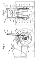
- FIG. 1 - 4 the general structure of an orchard tractor having a telescopic rollover protective structure mounted thereto can best be seen.
- Any left and right references are used as a matter of convenience and are determined by standing at the rear of the tractor 10 facing the forward end, the direction of travel.
- the tractor 10 is supported above the ground G by a conventional front axle rotatably supporting wheels (not shown) and a conventional rear axle 11 rotatably supporting a pair of rear wheels 12 drivingly coupled in a known manner to a transmission 14 transferring operable power from a standard engine (not shown).
- the orchard tractor 10 is also provided with an operator's seat 15 and operative controls 16 for supporting the operator on the tractor 10 and controlling the operation thereof.
- a pair of generally upright, laterally spaced support members 22 extend upwardly from the rear axle 11 and are joined by a laterally extending cross beam 23 providing structural rigidity therefor.
- Each vertically extending support member 22 defines a generally vertically oriented opening 24 which receives the protective member 25 for generally vertical sliding movement relative thereto.
- the protective member 25 is constructed in an inverted U-shaped configuration having generally vertically extending legs 26 interconnected at the upper portion thereof by a laterally extending cross member 27 forming the bight of the inverted U-shaped protective member 25.
- the ROPS 20 further includes a releasable locking mechanism 30 which is attached to each of the support members 22 and can be manipulated to engage the corresponding legs 26 of the protective member 25 to restrain the movement thereof relative to the support members 22.
- Each locking mechanism 30 includes a clamping apparatus 31 which is received through the cross beam 23.
- the clamping apparatus 31 is constructed with a hook member 32 having a necked-down portion 33 forming one end thereof and being engageable with an opening in the corresponding leg 26 of the protective member 25 and an adjustment link 34 threaded onto and translatable along an opposing threaded end 39 of the hook member 32 for purposes described in greater detail below.
- a compression spring 38 is concentrically mounted on the threaded end 39 of the hook member 32 and compressed between the adjustment link 34 and the cross beam 23 to bias the hook member 32 into engagement with the protective member leg 26.
- the releasable locking mechanism 30 also includes a threaded member 35 threadably received through the adjustment link 34 and engageable with the opposing side of the corresponding leg 26 of the protective member 25 from the hook member 32.
- the threaded member 35 is provided with a necked-down portion 36 to engage a corresponding opening in the protective member leg 26.
- the threaded member 35 is also provided with an actuation lever 37 to facilitate the rotation of the threaded member 35, as will be described in greater detail below.
- Figs. 1 - 6 it can be seen that the telescopic ROPS is provided with a counterbalance mechanism 40 operatively associated with both protective members legs 26.
- the details of the counterbalance mechanism 40 is best seen in Figs. 5 and 6, in which the left side of the ROPS 20 is depicted, although one skilled in the art will readily realize that the description of the counterbalance mechanism 40 associated with the left transverse leg 26 is equally applicable to the opposing right transverse leg 26.
- the counterbalance mechanism 40 includes a compression biasing means 41 associated with each respective protective member leg 26.
- the compression biasing means 41 includes a compression spring 45 seated against a pedestal 42 affixed to the corresponding support member 22 and positioned below the rear axle 11 to provide adequate room for the generally vertical movement of the protective member 25.
- the compression spring 45 is concentrically mounted around a telescopic rod 46 having a base portion 47 connected to the pedestal 42 and an upwardly extensible portion 48 connected to the protective member leg 26.
- the purpose of the telescopic rod 46 is to limit lateral movement of the compression spring 45 during movement of the protective member 25.
- the compression biasing means 41 is generally housed internally of the protective member leg 26, except that the base portion 47 of the telescopic rod 46 and the corresponding portion of the extended compression spring 45 is exposed below the protective member leg 26 when the protective member 25 is raised to a raised position, as depicted in Figs. 1, 2, 5 and 6.
- the ROPS 20 is positionable between an upper raised position, shown in Figs. 1 and 2 and a lower, retracted position depicted in Figs. 3 and 4.
- the cross member 27 of the protective member 25 is lowered to a position below the operator's seat 15 and immediately above the cross beam 23 of the support frame 22.
- the protective member 25 will not typically interfere with low hanging branches, such as found in an orchard, since the cross member 27 is positioned lower than the body of the operator.
- the pedestal 42 is positioned such that the protective member leg 26 can be fully accommodated in this lowered position, with the compression spring 45 fully compressed and housed within the internal hollow chamber of the leg 26.
- the counterbalance mechanism 40 will offset at least most of the weight of the protective member 25 when the ROPS 20 is lowered into the retracted position.
- the size of the compression spring 45 would be such that the weight of the protective member 25 will effect some compression of the spring 45 when the releasable locking mechanisms 35 is loosened to permit a retraction of the protective member 25.
- a rotation of the threaded member 35 facilitated by engagement of the actuation lever 37, withdraws the necked-down portion 36 of the threaded member 35 from engagement with the protective member leg 26.
- the hook member 32 is dislodged from the opposing side of the protective member leg 26 by effecting a manual compression of the compression spring 38 by pressing against the adjustment link 34 so that the necked-down portion 33 completely disengages the corresponding leg 26.
- the protective member 25 should drop slightly, compressing the compression spring 45 until the force of the compression spring 45 completely offsets the weight of the protective member 25. Since the protective member 25 moves slightly when the clamping member 31 disengages the legs 26, a release of the manual pressure placed on the adjustment links 34 will not cause a reengagement of the hook members 32 with the corresponding legs 26 because of the resultant misalignment of the necked-down portions 33 with the corresponding opening in the legs 26. The operator then must manually grab the protective member 25 to effect a retraction of the legs 26 into the corresponding support members 22, which as shown in Figs. 2 and 4 have an open design to permit the passage of the legs 26 toward the corresponding pedestals 42. Once the protective member 25 has been fully retracted into the support members 22, the clamping apparatus 31 can be reengaged with the protective member 25 to retain the protective member 25 in its retracted position, as depicted in Figs. 3 and 4.
- the operation of the releasable locking mechanism 30 can best be seen.
- the threaded member 35 To effect a disengagement of the clamping apparatus 31 from the protective member 25, the threaded member 35 must be rotated to effect a withdrawal of the necked-down portion 36 from the corresponding protective member leg 26 and the compression spring 38 must be overcome to retract the necked-down portion 33 of the hook member 32 as is described above.
- the clamping apparatus 31 can be reengaged therewith by the biasing force exerted by the compression spring 38 urging the necked-down portion 33 into an appropriately positioned hole in the corresponding protective member leg 26 to temporarily fix the protective member 25 against the support members 22.
- a rotation of the threaded member 35 to move the threaded member 35 into engagement with the corresponding protective member leg 26 causes the necked-down portion 36 to pass into another properly positioned hole in the leg 26 until the body of the threaded member 35, forming a shoulder adjacent the necked-down portion 36, rests against the leg 26.
- the operator To return the protective member 25 into its raised position, thereby re-instituting the rollover protection for the operator, the operator must first disengage the releasable locking mechanisms 30, as described above, and raise the protective member 25 into its fully extended raised position, whereupon the clamping apparatus 31 is reengaged with the protective member legs 26 to fix the protective member 25 in its raised position.
- the biasing force of the compression springs 45 housed within the protective member legs 26 assists the raising of the protective member 25.
- an outwardly protruding tab 49 is affixed to the bottom of each respective protective member leg 26 to engage the corresponding support member 22 when the protective member 25 is positioned at or above the fully raised position.
- the provision of the adjustment link 34 threaded onto the end 39 of the hook member 32 and threadably receiving the member 35 for translational movement relative thereto permits the adjustment of the relative positional relationship between the hook member 32 and the threaded member 35 and of the amount of pre-compression of the compression spring 38 to permit a proper engagement of the protective member legs 26.
- This adjustment can be effected by a rotation of the adjustment link 34 along the threaded end 39 in the direction required.
- a jam nut 53 threaded onto the end 39 of the hook member 32 can be used to help fix the adjustment link 34 into the selected position.
- the wheel spacing between the opposing rear wheels 12 is so narrow that the positioning of a telescopic ROPS 20 internally of the rear wheels 12, as depicted in Figs. 1 - 4 does not provide adequate rollover protection for the operator.
- the hollow cross member 27 can house laterally extensible wing members 51, which must be completely retractable into the body of the cross member 27 when the protective member 25 is lowered into the retracted position, shown in Figs. 3 and 4, because of the restricted spacing between the rear wheels 12.
- a latching mechanism 52 can be provided to interengage the cross member 27 and the extendable wing 51.
- the positioning of the latching mechanism 52 need only be convenient to the operatorwhile permitting a selective interengagement between the cross member 27 and the wings 51.
Landscapes
- Engineering & Computer Science (AREA)
- Mechanical Engineering (AREA)
- Body Structure For Vehicles (AREA)
- Agricultural Machines (AREA)
Applications Claiming Priority (2)
| Application Number | Priority Date | Filing Date | Title |
|---|---|---|---|
| US07/656,922 US5129676A (en) | 1991-02-19 | 1991-02-19 | Counterbalanced telescopic rollbar for tractors |
| US656922 | 1996-06-04 |
Publications (2)
| Publication Number | Publication Date |
|---|---|
| EP0500261A1 true EP0500261A1 (fr) | 1992-08-26 |
| EP0500261B1 EP0500261B1 (fr) | 1995-09-20 |
Family
ID=24635128
Family Applications (1)
| Application Number | Title | Priority Date | Filing Date |
|---|---|---|---|
| EP92301165A Expired - Lifetime EP0500261B1 (fr) | 1991-02-19 | 1992-02-12 | Arceau de sécurité télescopique équilibré pour tracteur |
Country Status (3)
| Country | Link |
|---|---|
| US (1) | US5129676A (fr) |
| EP (1) | EP0500261B1 (fr) |
| DE (1) | DE69204867T2 (fr) |
Cited By (7)
| Publication number | Priority date | Publication date | Assignee | Title |
|---|---|---|---|---|
| EP0623492A1 (fr) * | 1993-05-03 | 1994-11-09 | Bayerische Motoren Werke Aktiengesellschaft | Dispositif à arceau de sécurité pour un véhicule automobile |
| EP0729867A1 (fr) * | 1993-05-03 | 1996-09-04 | Bayerische Motoren Werke Aktiengesellschaft, Patentabteilung AJ-3 | Dispositif à arceau de sécurité pour véhicule automobile |
| US5626361A (en) * | 1993-05-03 | 1997-05-06 | Bayerische Motoren Werke Ag | Roll-over protection arrangement for a motor vehicle |
| EP0899169A1 (fr) * | 1997-08-06 | 1999-03-03 | Richard Riley | Dispositif automatique de déverrouillage et appareil de retenue du conducteur pour engins de travaux mobiles |
| WO2002004259A1 (fr) * | 2000-07-07 | 2002-01-17 | The Government Of The United States Of America As Represented By The Secretary Of The Department Of Health And Human Services, Centers For Disease Control And Prevention | Systeme de protection en cas de renversement a deploiement automatique |
| EP1095823A3 (fr) * | 1999-10-29 | 2003-08-06 | ISE Innomotive Systems Europe GmbH | Dispositif de protection contre le retournement pour véhicules |
| WO2013083864A1 (fr) | 2012-07-03 | 2013-06-13 | Air-Rops Na 2012, S.L. | Structure de protection déployable contre le retournement de véhicules |
Families Citing this family (24)
| Publication number | Priority date | Publication date | Assignee | Title |
|---|---|---|---|---|
| DE4100506C1 (fr) * | 1991-01-10 | 1992-05-21 | Mercedes-Benz Aktiengesellschaft, 7000 Stuttgart, De | |
| USD365351S (en) | 1994-08-18 | 1995-12-19 | Schroyer Marlene J | Tractor roll bar |
| US5529342A (en) * | 1995-05-11 | 1996-06-25 | Caterpillar Inc. | Rollover protective structure and method |
| US5779272A (en) * | 1996-11-07 | 1998-07-14 | Case Corporation | Roll-over protection system |
| US5839758A (en) * | 1997-03-03 | 1998-11-24 | New Holland North America, Inc. | Roll-over protective system for tractors |
| US7438319B2 (en) * | 2006-02-09 | 2008-10-21 | Bruce Russell Lee Cooper | Modular roll protection structure (ROPS) for compact tractors |
| US7971904B2 (en) * | 2006-06-20 | 2011-07-05 | Deere & Company | Rollover protection system |
| US7571691B2 (en) * | 2006-07-15 | 2009-08-11 | Russikoff Ronald K | Retractable bimini top device |
| CA2662029C (fr) * | 2006-09-04 | 2014-08-05 | David Andrew Robertson | Systeme de protection contre le capotage |
| DE102006048085B4 (de) * | 2006-10-10 | 2009-05-07 | Ise Automotive Gmbh | Überrollschutzsystem für Kraftfahrzeuge mit mindestens einem aktiv aufstellbaren Überrollbügel |
| US8029019B2 (en) * | 2009-01-29 | 2011-10-04 | Deere & Company | ROPS mounting assembly |
| US10493939B2 (en) | 2015-02-13 | 2019-12-03 | Excel Industries, Inc. | Lever-actuated operator protection apparatus |
| US8905434B1 (en) | 2009-11-12 | 2014-12-09 | Excel Industries, Inc. | Rollover protection apparatus |
| US11724658B2 (en) | 2009-11-12 | 2023-08-15 | Excel Industries, Inc. | Control system for a terrain working vehicle having an operator protection apparatus |
| US10377333B2 (en) | 2009-11-12 | 2019-08-13 | Excel Industries, Inc. | Deployable operator protection apparatus with an over-center linkage |
| US8528924B1 (en) | 2009-11-12 | 2013-09-10 | Excel Industries, Inc. | Rollover protection system |
| US9573548B2 (en) | 2015-02-13 | 2017-02-21 | Excel Industries, Inc. | Operator protection apparatus with an over-center linkage |
| US11198408B2 (en) | 2009-11-12 | 2021-12-14 | Excel Industries, Inc. | Control system for a terrain working vehicle having an operator protection apparatus |
| DE202011050733U1 (de) * | 2011-07-15 | 2012-10-25 | Hans Hermann Bergmann | Mobile Arbeitsmaschine mit höhenbeweglichem Fahrerschutz |
| US9616837B1 (en) | 2014-06-03 | 2017-04-11 | Excel Industries, Inc. | Forward folding roll bar assembly |
| US20150367897A1 (en) * | 2015-08-28 | 2015-12-24 | Caterpillar Paving Products Inc. | Adjustable cab system for machine |
| US10696260B2 (en) * | 2017-10-30 | 2020-06-30 | Deere & Company | Multiple pivot rollover protection structure |
| US10501039B2 (en) * | 2017-12-22 | 2019-12-10 | Kubota Corporation | Work vehicle having ROPS |
| ES2852898T3 (es) * | 2018-04-24 | 2021-09-14 | David Robertson | Un aparato de protección contra vuelcos |
Citations (7)
| Publication number | Priority date | Publication date | Assignee | Title |
|---|---|---|---|---|
| CH414372A (de) * | 1963-06-14 | 1966-05-31 | Duncan Alexander | Uberschlagbügel für Fahrzeuge, insbesondere Traktoren |
| DE1919360A1 (de) * | 1968-04-17 | 1970-08-27 | Richard Wiesauer | UEberschlag-Schutzvorrichtung an Traktoren |
| DE2025871B2 (de) * | 1970-05-27 | 1973-04-12 | Kettler, Paul Erich, 6361 Ockstadt | Schlepper, insbesondere schmalspurschlepper fuer weinberg-, hopfenund andere obstkulturen, mit einem in der hoehe verstellbaren u-foermigen schutzbuegel |
| US3802720A (en) * | 1973-03-15 | 1974-04-09 | Brown R | Outrigger roll bar apparatus for tractor vehicles |
| FR2299992A1 (fr) * | 1975-02-10 | 1976-09-03 | Fritzmeier Kg Georg | Cadre de protection en cas de culbute pour vehicules utilitaires |
| FR2314090A1 (fr) * | 1975-06-10 | 1977-01-07 | Belin Ets | Dispositif de securite pour tracteur |
| DE2543077A1 (de) * | 1975-09-26 | 1977-03-31 | Peter Fischer | Abklappbarer sicherheitsbuegel fuer zugfahrzeuge |
Family Cites Families (7)
| Publication number | Priority date | Publication date | Assignee | Title |
|---|---|---|---|---|
| US3292726A (en) * | 1964-12-21 | 1966-12-20 | Jr Emile Jette | Automobile safety device having roof reinforcing bar |
| GB1211640A (en) * | 1967-10-26 | 1970-11-11 | Lansing Bagnall Ltd | Improvements in or relating to industrial lift trucks |
| GB1522285A (en) * | 1977-02-02 | 1978-08-23 | White S | Safety frames for tractors |
| US4148504A (en) * | 1977-04-04 | 1979-04-10 | Rushing John D | Protective guard for passenger vehicle |
| GB2163585B (en) * | 1984-08-02 | 1987-11-25 | Heavy Transport | Vehicle anti-rollover devices |
| US4877265A (en) * | 1988-07-29 | 1989-10-31 | Deere & Company | Adjustable height vehicle roll-over bar |
| DE3826392A1 (de) * | 1988-08-03 | 1990-02-15 | Deere & Co | Ueberschlagvorrichtung fuer ein fahrzeug |
-
1991
- 1991-02-19 US US07/656,922 patent/US5129676A/en not_active Expired - Fee Related
-
1992
- 1992-02-12 DE DE69204867T patent/DE69204867T2/de not_active Expired - Fee Related
- 1992-02-12 EP EP92301165A patent/EP0500261B1/fr not_active Expired - Lifetime
Patent Citations (7)
| Publication number | Priority date | Publication date | Assignee | Title |
|---|---|---|---|---|
| CH414372A (de) * | 1963-06-14 | 1966-05-31 | Duncan Alexander | Uberschlagbügel für Fahrzeuge, insbesondere Traktoren |
| DE1919360A1 (de) * | 1968-04-17 | 1970-08-27 | Richard Wiesauer | UEberschlag-Schutzvorrichtung an Traktoren |
| DE2025871B2 (de) * | 1970-05-27 | 1973-04-12 | Kettler, Paul Erich, 6361 Ockstadt | Schlepper, insbesondere schmalspurschlepper fuer weinberg-, hopfenund andere obstkulturen, mit einem in der hoehe verstellbaren u-foermigen schutzbuegel |
| US3802720A (en) * | 1973-03-15 | 1974-04-09 | Brown R | Outrigger roll bar apparatus for tractor vehicles |
| FR2299992A1 (fr) * | 1975-02-10 | 1976-09-03 | Fritzmeier Kg Georg | Cadre de protection en cas de culbute pour vehicules utilitaires |
| FR2314090A1 (fr) * | 1975-06-10 | 1977-01-07 | Belin Ets | Dispositif de securite pour tracteur |
| DE2543077A1 (de) * | 1975-09-26 | 1977-03-31 | Peter Fischer | Abklappbarer sicherheitsbuegel fuer zugfahrzeuge |
Non-Patent Citations (1)
| Title |
|---|
| PATENT ABSTRACTS OF JAPAN vol. 2, no. 36 10 March 1978 & JP-A-52 153 519 ( KUBOTA ) 20 December 1977 * |
Cited By (7)
| Publication number | Priority date | Publication date | Assignee | Title |
|---|---|---|---|---|
| EP0623492A1 (fr) * | 1993-05-03 | 1994-11-09 | Bayerische Motoren Werke Aktiengesellschaft | Dispositif à arceau de sécurité pour un véhicule automobile |
| EP0729867A1 (fr) * | 1993-05-03 | 1996-09-04 | Bayerische Motoren Werke Aktiengesellschaft, Patentabteilung AJ-3 | Dispositif à arceau de sécurité pour véhicule automobile |
| US5626361A (en) * | 1993-05-03 | 1997-05-06 | Bayerische Motoren Werke Ag | Roll-over protection arrangement for a motor vehicle |
| EP0899169A1 (fr) * | 1997-08-06 | 1999-03-03 | Richard Riley | Dispositif automatique de déverrouillage et appareil de retenue du conducteur pour engins de travaux mobiles |
| EP1095823A3 (fr) * | 1999-10-29 | 2003-08-06 | ISE Innomotive Systems Europe GmbH | Dispositif de protection contre le retournement pour véhicules |
| WO2002004259A1 (fr) * | 2000-07-07 | 2002-01-17 | The Government Of The United States Of America As Represented By The Secretary Of The Department Of Health And Human Services, Centers For Disease Control And Prevention | Systeme de protection en cas de renversement a deploiement automatique |
| WO2013083864A1 (fr) | 2012-07-03 | 2013-06-13 | Air-Rops Na 2012, S.L. | Structure de protection déployable contre le retournement de véhicules |
Also Published As
| Publication number | Publication date |
|---|---|
| US5129676A (en) | 1992-07-14 |
| EP0500261B1 (fr) | 1995-09-20 |
| DE69204867D1 (de) | 1995-10-26 |
| DE69204867T2 (de) | 1996-04-04 |
Similar Documents
| Publication | Publication Date | Title |
|---|---|---|
| EP0500261B1 (fr) | Arceau de sécurité télescopique équilibré pour tracteur | |
| US4275984A (en) | Parking stand | |
| US5575026A (en) | Emergency stretcher with X-frame support | |
| US3961809A (en) | Safety step for vehicles | |
| US4119342A (en) | Convertible chair structure | |
| US4119329A (en) | Farm apparatus | |
| CA3123241C (fr) | Ensemble pont d'accès et ensemble poignée pour une plate-forme de travail élévatrice d'un véhicule | |
| US4180143A (en) | Step for vehicles | |
| EP0497498B1 (fr) | Perfectionnements relatifs aux remorques | |
| US6036208A (en) | Truck bed pull out step system | |
| US4274172A (en) | Ramps | |
| CA1249702A (fr) | Poignee servant a deverrouiller la grille de securite d'un lit d'enfant | |
| US8590917B2 (en) | Fifth-wheel trailer with an adjustable floor and a method for its use | |
| US7780389B1 (en) | Door installation system | |
| US5445399A (en) | Retractable hand truck having positive leg lock | |
| CA2497082A1 (fr) | Civiere avec plate-forme flottante specialisee demontable et multifonctionnelle de support de malade | |
| US7240470B2 (en) | Drive over mower deck | |
| US5474311A (en) | Vehicle bench seat retractable wheel carriage | |
| US4630570A (en) | Portable stock handling unit | |
| US4252492A (en) | Detachable lift unit for pickup trucks | |
| CA1183493A (fr) | Dispositif d'attelage pour l'avant d'un vehicule | |
| US4218094A (en) | Safety brace | |
| US20030017038A1 (en) | Automatic fold-up jack for an implement transporter | |
| DE7735470U1 (de) | Bettcouch mit fernsehkopfstuetze | |
| US4093257A (en) | Truck ladder |
Legal Events
| Date | Code | Title | Description |
|---|---|---|---|
| PUAI | Public reference made under article 153(3) epc to a published international application that has entered the european phase |
Free format text: ORIGINAL CODE: 0009012 |
|
| AK | Designated contracting states |
Kind code of ref document: A1 Designated state(s): DE FR GB IT |
|
| 17P | Request for examination filed |
Effective date: 19930212 |
|
| RAP1 | Party data changed (applicant data changed or rights of an application transferred) |
Owner name: NEW HOLLAND FORD LIMITED |
|
| 17Q | First examination report despatched |
Effective date: 19940803 |
|
| GRAA | (expected) grant |
Free format text: ORIGINAL CODE: 0009210 |
|
| AK | Designated contracting states |
Kind code of ref document: B1 Designated state(s): DE FR GB IT |
|
| REF | Corresponds to: |
Ref document number: 69204867 Country of ref document: DE Date of ref document: 19951026 |
|
| ET | Fr: translation filed | ||
| ITF | It: translation for a ep patent filed | ||
| RAP2 | Party data changed (patent owner data changed or rights of a patent transferred) |
Owner name: NEW HOLLAND U.K. LIMITED |
|
| PLBE | No opposition filed within time limit |
Free format text: ORIGINAL CODE: 0009261 |
|
| 26N | No opposition filed | ||
| REG | Reference to a national code |
Ref country code: GB Ref legal event code: IF02 |
|
| REG | Reference to a national code |
Ref country code: FR Ref legal event code: CD |
|
| PGFP | Annual fee paid to national office [announced via postgrant information from national office to epo] |
Ref country code: GB Payment date: 20060103 Year of fee payment: 15 |
|
| PGFP | Annual fee paid to national office [announced via postgrant information from national office to epo] |
Ref country code: FR Payment date: 20060110 Year of fee payment: 15 |
|
| PGFP | Annual fee paid to national office [announced via postgrant information from national office to epo] |
Ref country code: DE Payment date: 20060131 Year of fee payment: 15 |
|
| PGFP | Annual fee paid to national office [announced via postgrant information from national office to epo] |
Ref country code: IT Payment date: 20060228 Year of fee payment: 15 |
|
| GBPC | Gb: european patent ceased through non-payment of renewal fee |
Effective date: 20070212 |
|
| REG | Reference to a national code |
Ref country code: FR Ref legal event code: ST Effective date: 20071030 |
|
| PG25 | Lapsed in a contracting state [announced via postgrant information from national office to epo] |
Ref country code: DE Free format text: LAPSE BECAUSE OF NON-PAYMENT OF DUE FEES Effective date: 20070901 |
|
| PG25 | Lapsed in a contracting state [announced via postgrant information from national office to epo] |
Ref country code: GB Free format text: LAPSE BECAUSE OF NON-PAYMENT OF DUE FEES Effective date: 20070212 Ref country code: FR Free format text: LAPSE BECAUSE OF NON-PAYMENT OF DUE FEES Effective date: 20070228 |
|
| PG25 | Lapsed in a contracting state [announced via postgrant information from national office to epo] |
Ref country code: IT Free format text: LAPSE BECAUSE OF NON-PAYMENT OF DUE FEES Effective date: 20070212 |