EP0500281B1 - Aufzeichnungsgerät mit automatischer Regenierfunktion - Google Patents
Aufzeichnungsgerät mit automatischer Regenierfunktion Download PDFInfo
- Publication number
- EP0500281B1 EP0500281B1 EP92301239A EP92301239A EP0500281B1 EP 0500281 B1 EP0500281 B1 EP 0500281B1 EP 92301239 A EP92301239 A EP 92301239A EP 92301239 A EP92301239 A EP 92301239A EP 0500281 B1 EP0500281 B1 EP 0500281B1
- Authority
- EP
- European Patent Office
- Prior art keywords
- recording
- recording head
- head
- unevenness
- ink
- Prior art date
- Legal status (The legal status is an assumption and is not a legal conclusion. Google has not performed a legal analysis and makes no representation as to the accuracy of the status listed.)
- Expired - Lifetime
Links
Images



Classifications
-
- B—PERFORMING OPERATIONS; TRANSPORTING
- B41—PRINTING; LINING MACHINES; TYPEWRITERS; STAMPS
- B41J—TYPEWRITERS; SELECTIVE PRINTING MECHANISMS, i.e. MECHANISMS PRINTING OTHERWISE THAN FROM A FORME; CORRECTION OF TYPOGRAPHICAL ERRORS
- B41J2/00—Typewriters or selective printing mechanisms characterised by the printing or marking process for which they are designed
- B41J2/005—Typewriters or selective printing mechanisms characterised by the printing or marking process for which they are designed characterised by bringing liquid or particles selectively into contact with a printing material
- B41J2/01—Ink jet
- B41J2/21—Ink jet for multi-colour printing
- B41J2/2132—Print quality control characterised by dot disposition, e.g. for reducing white stripes or banding
- B41J2/2139—Compensation for malfunctioning nozzles creating dot place or dot size errors
-
- B—PERFORMING OPERATIONS; TRANSPORTING
- B41—PRINTING; LINING MACHINES; TYPEWRITERS; STAMPS
- B41J—TYPEWRITERS; SELECTIVE PRINTING MECHANISMS, i.e. MECHANISMS PRINTING OTHERWISE THAN FROM A FORME; CORRECTION OF TYPOGRAPHICAL ERRORS
- B41J2/00—Typewriters or selective printing mechanisms characterised by the printing or marking process for which they are designed
- B41J2/005—Typewriters or selective printing mechanisms characterised by the printing or marking process for which they are designed characterised by bringing liquid or particles selectively into contact with a printing material
- B41J2/01—Ink jet
- B41J2/135—Nozzles
- B41J2/165—Prevention or detection of nozzle clogging, e.g. cleaning, capping or moistening for nozzles
- B41J2/16579—Detection means therefor, e.g. for nozzle clogging
-
- B—PERFORMING OPERATIONS; TRANSPORTING
- B41—PRINTING; LINING MACHINES; TYPEWRITERS; STAMPS
- B41J—TYPEWRITERS; SELECTIVE PRINTING MECHANISMS, i.e. MECHANISMS PRINTING OTHERWISE THAN FROM A FORME; CORRECTION OF TYPOGRAPHICAL ERRORS
- B41J2/00—Typewriters or selective printing mechanisms characterised by the printing or marking process for which they are designed
- B41J2/005—Typewriters or selective printing mechanisms characterised by the printing or marking process for which they are designed characterised by bringing liquid or particles selectively into contact with a printing material
- B41J2/01—Ink jet
- B41J2/21—Ink jet for multi-colour printing
- B41J2/2132—Print quality control characterised by dot disposition, e.g. for reducing white stripes or banding
- B41J2/2146—Print quality control characterised by dot disposition, e.g. for reducing white stripes or banding for line print heads
-
- B—PERFORMING OPERATIONS; TRANSPORTING
- B41—PRINTING; LINING MACHINES; TYPEWRITERS; STAMPS
- B41J—TYPEWRITERS; SELECTIVE PRINTING MECHANISMS, i.e. MECHANISMS PRINTING OTHERWISE THAN FROM A FORME; CORRECTION OF TYPOGRAPHICAL ERRORS
- B41J29/00—Details of, or accessories for, typewriters or selective printing mechanisms not otherwise provided for
- B41J29/38—Drives, motors, controls or automatic cut-off devices for the entire printing mechanism
- B41J29/393—Devices for controlling or analysing the entire machine ; Controlling or analysing mechanical parameters involving printing of test patterns
-
- B—PERFORMING OPERATIONS; TRANSPORTING
- B41—PRINTING; LINING MACHINES; TYPEWRITERS; STAMPS
- B41J—TYPEWRITERS; SELECTIVE PRINTING MECHANISMS, i.e. MECHANISMS PRINTING OTHERWISE THAN FROM A FORME; CORRECTION OF TYPOGRAPHICAL ERRORS
- B41J3/00—Typewriters or selective printing or marking mechanisms characterised by the purpose for which they are constructed
- B41J3/44—Typewriters or selective printing mechanisms having dual functions or combined with, or coupled to, apparatus performing other functions
-
- B—PERFORMING OPERATIONS; TRANSPORTING
- B41—PRINTING; LINING MACHINES; TYPEWRITERS; STAMPS
- B41J—TYPEWRITERS; SELECTIVE PRINTING MECHANISMS, i.e. MECHANISMS PRINTING OTHERWISE THAN FROM A FORME; CORRECTION OF TYPOGRAPHICAL ERRORS
- B41J2/00—Typewriters or selective printing mechanisms characterised by the printing or marking process for which they are designed
- B41J2/005—Typewriters or selective printing mechanisms characterised by the printing or marking process for which they are designed characterised by bringing liquid or particles selectively into contact with a printing material
- B41J2/01—Ink jet
- B41J2/135—Nozzles
- B41J2/165—Prevention or detection of nozzle clogging, e.g. cleaning, capping or moistening for nozzles
- B41J2/16517—Cleaning of print head nozzles
- B41J2/16552—Cleaning of print head nozzles using cleaning fluids
Definitions
- the present invention relates to a recording apparatus for forming an image according to an image signal or an original image, and more particularly to an ink jet recording apparatus.
- the ink jet recording apparatus is attracting particular attention for full color image formation, because such apparatus, which forms dot records by discharging ink droplets from nozzles of a recording head, is advantageous in its configuration and in the running cost.
- the recording is generally achieved by scanning motions of the recording head, having a nozzle array of a certain width (for example about 16 mm) in longitudinal and transversal directions relative to a recording material.
- discharge failure proper ink discharge from the nozzles
- the recording operation may be conducted continuously on a very long recording material of 100 meters or longer, so that the unevenness resulting from discharge failure during such recording operation poses a serious problem.
- said web-shaped recording material is composed of woven fabric, the probability of such discharge failure is significantly higher than in the ordinary recording paper, particularly coated paper, because fine fiber dusts tend to deposit on or in the vicinity of the nozzles of the recording head.
- Japanese Patent No. 1-130948 discloses an ink jet printer having a test printing section and recovery means provided on one side of a printing section as well as reading means. A pattern printed for test is read by said reading means to detect defective nozzles whereby a recovery operation takes place.
- a concern of the present invention is to provide a recording apparatus capable of constantly providing stable recorded images with a simple structure.
- Another concern of the present invention is to provide a recording apparatus capable of stable recording on a web-shaped recording medium.
- Still another concern of the present invention is to provide a recording apparatus capable of stable recording on a recording medium with a rough surface such as woven fabric.
- the recording apparatus of the present invention is capable of preventing the deterioration of image quality by suitably checking the unevenness or discharge failure of the recording head and effecting unevenness correction or discharge recovery operation, or requesting the operator to replace the recording head.
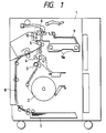
- Fig. 1 is a cross-sectional view of a recording apparatus of the present invention, wherein shown are a main body 1; a roll 2 of web-shaped recording material (medium); a cutter 4 for cutting the recording material into a predetermined length; paired transport rollers 3, 5 for transporting the recording material in a predetermined direction; and a sub scanning roller 6 for positioning the recording material by precisely transporting the same by an amount corresponding to the recording width of a recording head to be explained later.
- the above-mentioned components constitute a transport path for the recording material supplied from the roll 2.
- a cassette 7 for storing sheet-shaped recording materials
- guide members 8 for guiding the recording material from the cassette 7 into the transport path from said roll 2, immediately in front of the transport rollers 5
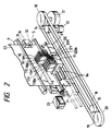
- a carriage 9 bearing a recording head (not shown) and movably supported by a pair of main scanning rails 9a in a direction perpendicular to the plane of the drawing
- a platen member 10 positioned opposite to said carriage 9 across the recording material and provided with suction means that operates for example, by air suction or electrostatic suction, in order to maintain the recording material in flat state and to prevent the recording material from contacting the recording head during the recording operation.
- the carriage 9 is provided with recording heads 9C, 9M, 9Y, 9Bk respectively corresponding to cyan, magenta, yellow and black colors.
- An ink supply system 11 for supplying said recording heads with inks is provided with ink cartridges 11C, 11M, 11Y, 11Bk respectively corresponding to said colors. Inks are supplied to said recording heads, by means of unrepresented pumps, through tubes 12C, 12M, 12Y, 12Bk.
- a motor 13 drives the carriage 9 in the main scanning direction (lateral direction in the drawing), by means of a pulley 14 fixed to said motor 13, another pulley 15 and a belt 16.
- a motor 17 drives the ink supply system 11 in the main scanning direction, in synchronization with the carriage 9, by means of a pulley 18 fixed to said motor 17, another pulley 19 and a belt 20.
- a cap member 23 is provided at a position for effecting an operation for eliminating the causes of image quality deterioration (hereinafter called discharge recovery operation). Said cap member 23 serves to cover the nozzle faces of the recording heads 9C, 9M, 9Y, 9Bk, and the ink is discharged or pushed out from the nozzles in such capped state, by activation or pressurization of the recording heads.
- high-speed air flow is directed toward the nozzle faces of the recording heads in the cap member 23, thus blowing off thus expelled ink and dusts from the nozzle faces, and eliminating the discharge failure and unevenness.
- a monitor 31 for monitoring the recording state of the recording heads reads a predetermined pattern (of uniform density), printed at a predetermined interval on the right-end margin of the recording material 22.
- FIG. 3 shows the details of said monitor 31.
- a calibration pattern 32 containing each of cyan, magenta, yellow and black colors in uniform density and by a scanning line, is printed at a predetermined interval at an end margin of the recording material 22.
- the number of elements in said sensor is preferably at least equal to that of the recording elements in the recording head.
- the output of said sensor 35 is used for detecting the presence of discharge failure in the recording head and whether the unevenness of printing exceeds a predetermined level, and the aforementioned discharge recovery operation is conducted if necessary.
- a recording material sensor (not shown) positioned in front of the transport rollers 5 detects a recording material fed from the roll 2 or the cassette 7, the transport rollers 5 and the sub scanning roller 6 advances the recording material by a predetermined amount, until the leading end thereof reaches the sub scanning roller 6.
- the carriage 9 and the ink supply system 11 are respectively driven by the motors 13, 17 in the scanning direction (to the right in Fig. 2).
- the recording heads 9C, 9M, 9Y, 9Bk effect recording with a width I, according to image signals.
- the carriage 9 and the ink supply system 11 are returned to a predetermined position at the left side in Fig. 2, and the recording material 22 is simultaneously advanced by the motor 21, by an amount precisely corresponding to said printing width I.
- the recording material 22 is discharged from the apparatus.
- Fig. 4 shows the output signal of the sensor 35 of said monitor 31, wherein the abscissa corresponds to the pixels of said sensor 35, while the ordinate indicates the output of each pixel.
- the output of the sensor 35 is subjected to so-called shading correction, utilizing the recording material before printing as the white level. Since each pixel output corresponds to each nozzle of the recording head, the amount of ink discharge from each nozzle can be determined.
- a discharge failure is identified if the output signal becomes larger, even in one position, than a slice level b which is larger by a predetermined amount than the average pixel output a . Also large unevenness is identified if the output signal becomes larger than a slice level c which is larger by a predetermined amount than said average a or becomes smaller than a slice level d which is smaller by a predetermined amount than said average a .
- the slice level b for detecting the discharge failure is preferably larger, by about 50 %, than the average a
- the slice levels c , d for unevenness detection are preferably different, by 5 to 10 %, from the average a .
- the pixel output values of the sensor 35 may be employed.
- the average value of mutually adjacent pixels for example three adjacent pixels of the sensor.
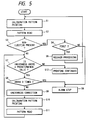
- Fig. 5 for explaining a calibration sequence for detecting the discharge failure and unevenness and effecting the discharge recovery operation.
- the calibration patterns are printed at a predetermined interval (step S1).
- Said calibration pattern is read by the monitor 31 (step S2), and the presence of discharge failure is discriminated by the algorithm explained above (step S3).
- step S4 If a discharge failure is identified, there is discriminated whether or not to effect the recovery operation (step S4).
- the discrimination in the step S4 depends on whether the recovery operation is already conducted in this sequence. This is based on an empirical fact that most discharge failures are resolved if the aforementioned discharge recovery operation is properly conducted.
- step S5 the sequence returns to the step S1 for calibration pattern printing, step S2 for pattern reading and step S3 for discrimination of the discharge failure. If the step S4 again identifies the discharge failure, the recovery operation is not conducted, but an alarm for a head trouble is given and the operation of the apparatus is interrupted (step S6).
- step S3 if the step S3 identifies the absence of discharge failure, there is discriminated the absence of unevenness, according to the unevenness discriminating algorithm explained before (step S7). If the unevenness is identified absent, the recording operation is continued (step S12). On the other hand, if the step S7 identifies that the unevenness is equal to or larger than a predetermined level, there is discriminated whether to effect the unevenness correction operation (step S8), and there is conducted the unevenness correction (step S9). The unevenness correction in the step S9 is conducted, based on the output signal of the pattern read in the step S2, by correcting the drive signal (signal duration or voltage) of the required nozzles of the recording head. Then a pattern of uniform density, same as printed in the step S1, is printed (step S10), and the printed pattern is read by the monitor 31 (step S11).
- steps S7, S8, S9, S10 and S11 are repeated by a predetermined number of cycles (three times in the present embodiment), and, if the level of unevenness is still high, an alarm for a head trouble is given and the operation of the apparatus is interrupted (step S6).
- This is based on an empirical fact that this unevenness correcting sequence generally provides a practically sufficient effect after three cycles though the effect becomes still enhanced with a further increased number of cycles, while a significant unevenness after three correcting cycles is mostly caused by a trouble based in the recording head, such as the expired service life thereof.
- the discharge state of the recording heads can be maintained in satisfactory manner, by conducting the above-explained calibration sequence for each of the cyan, magenta, yellow and black colors. Consequently the working rate of the apparatus can be improved even in the unmanned state, and such measure is particularly effective in case of using continuous web-shaped recording medium.
- the recording material is assumed to be ordinary paper, but similar effects can also be obtained for other recording materials such as woven fabric.
- This embodiment is featured by the presence of a recording material exclusive for calibration pattern printing.
- a recording material 41 exclusive for monitoring supplied from a roll 42 and taken up, after printing, on a roll 43.
- the sequences of printing and calibration in the present embodiment will not be explained further, as they are same as in the first embodiment.
- This embodiment enabling recording on the entire area of the recording material without any margin therein, avoids waste of the recording material and is particularly effective for long continuous recording.
- Fig. 7 is a perspective view of a recording head and related mechanisms of the present embodiment, wherein components equivalent to those in Fig. 2 are represented by same numbers.
- the carriage 9 is provided with the recording heads 9C, 9M, 9Y, 9Bk respectively corresponding to cyan, magenta, yellow and black colors.
- the ink supply system 11, for ink supply to said recording heads is provided with ink cartridges 11C, 11M, 11Y, 11Bk respectively corresponding to said colors.
- the ink supply is conducted, when the carriage is in a chain-lined position 26 (hereinafter called ink supply position), from said system 11 to sub tanks (not shown) of the carriage 9 by unrepresented pumps, as will be explained later in more detail.
- a motor 13 drives the carriage 9 in the main scanning direction (lateral direction in the drawing) by means of a drive pulley 14 fixed to said motor, a pulley 15 and a belt 16.
- a motor 27 drives the reserve carriage 25 in said main scanning direction by a drive pulley 28 fixed to said motor 27, another pulley 29 and a belt 30.
- Caps 24a, 24b are provided for respectively covering the nozzles of the recording heads of the carriage 9 and the reserve carriage 25 at the home positions thereof, thereby preventing viscosity increase of the inks.
- a main tank 45 receiving ink supply from the ink cartridge 11C; a pump 46 for effecting ink pressurization for discharge recovery for the recording head 9C and ink supply to a sub tank 53 provided on the carriage; a support member 47 supporting a connector of an ink supply tube and moveable laterally by a motor 48 and a feed screw 49; a tube 50 connecting the pump 46 with the support member 47 and having a connector member 50a at an end; a tube 51 provided at an end with a connector member 51a engageable with said connector member 50a and supplying ink to the recording head 9C, said connector member 51a being provided with a valve (not shown) which is normally closed and opened only when coupled with the connector member 50a; a tube 52 connecting the recording head 9C with a sub tank 53 provided on the carriage; a tube 54 for returning the ink, overflowing at the ink supply, from the sub tank, having a connector member 54a at an end; a tube 55 connecting the support member 47 with the main tank 45 and provided at an end with
- the ink is supplied, with said connector members mutually coupled at said ink supply position, by the pump 46 to the tubes 50, 51, recording head 9C, tube 52, and sub tank 53, and, when the sub tank 53 is filled, the overflowing ink is returned to the main tank 55 through the tubes 54, 55.
- the valve 56 is in the open state.
- the ink pressurization at the discharge recovery operation is conducted, also at said ink supply position, with the connector members being mutually coupled, by activating the pump 46 with the valve 56 closed, whereby the ink pressure in the supply path is elevated to expel the ink from the nozzles of the recording head.
- the ink supply to the recording head in the course of actual recording operation is conducted from the sub tank 53 through the tube 52.
- the carriage 9 is driven in the scanning direction (to the right in Fig. 7) by the motor 13.
- the recording heads 9C, 9M, 9Y, 9Bk effect recording with a width I, according to image signal.
- the carriage 9 After recording of a line, the carriage 9 is returned to a predetermined position at the left side, and the recording material 22 is advanced by a distance precisely corresponding to the printing width I.
- the above-explained sequence of recording and transportation of recording material is repeated for a predetermined number of cycles, and then the recording material 22 is discharged from the apparatus.
- Fig. 9 for explaining the calibration sequence for detecting the discharge failure or unevenness and effecting the discharge recovery operation in this third embodiment.
- This sequence is different from that of the first embodiment in Fig. 5, in the process when a trouble in the recording head is identified.
- the step S6 in Fig. 5 provides an alarm display and terminates the function of the apparatus.
- a step S16 provides the alarm for the trouble in the recording head and replaces the recording head by activating the reserve carriage 25.
- the present embodiment monitors the unevenness and discharge failure in the recording heads, effects correction for unevenness and discharge recovery operation when required, and automatically replaces the recording heads when recovery is identified as not being possible, thereby preventing the deterioration in image quality and avoiding the interruption of recording.
- the working rate of the apparatus can further be improved.
- the calibration pattern is printed in the margin of the recording material 22, but it is also possible, as in the second embodiment, to provide a small-sized recording material for said calibration pattern and to print the calibration pattern at a predetermined interval.
- the recording material is assumed to be composed of ordinary paper, but similar effects can be obtained on other recording materials such as woven fabric.
- the interval of detection of unevenness and discharge failure, or the timing of printing of the calibration pattern is not particularly defined, but such calibrating operation may be conducted every line or every certain number of lines.
- the abnormality can be detected on real time basis if the calibration is conducted every line.
- a loss in the recording speed can be prevented by conducting the calibration at every certain number of lines.
- Said interval is preferably varied according to the kind of the recording material. More specifically, said interval is preferably made shorter for a recording material with a rougher surface, such as woven cloth, since short fibers tend to adhere around the nozzles of the recording head.
- the present invention always monitors the unevenness and discharge failure of the recording heads, whereby the correction for unevenness and the discharge recovery operation can be realized in an unmanned state and the deterioration in image quality can be prevented.
- the present invention brings about a particular effect when applied to a recording head and an ink jet recording system utilizing thermal energy for ink discharge.
- This system is applicable to so-called on-demand recording or continuous recording, but is particularly effective in the on-demand recording because, in response to the application of at least a drive signal representing the recording information to an electrothermal converter element positioned corresponding to a liquid channel or a sheet containing liquid (ink) therein, said element generates thermal energy capable of causing a rapid temperature increase exceeding the nucleate boiling point, thereby inducing film boiling on a heat action surface of the recording head and thus forming a bubble in said liquid (ink), in one-to-one correspondence with said drive signal.
- Said liquid (ink) is discharged through a discharge opening by the growth and contraction of said bubble, thereby forming at least a liquid droplet.
- Said drive signal is preferably formed as a pulse, as it realizes instantaneous growth and contraction of the bubble, thereby attaining highly responsive discharge of the liquid (ink).
- Such a pulse-shaped drive signal is preferably that disclosed in the U.S. Patents Nos. 4,463,359 and 4,345,262. Also the conditions described in the U.S. Patent No. 4,313,124 relative to the temperature increase rate of said heat action surface allows to obtain further improved recording.
- the configuration of the recording head is given by the combinations of the liquid discharge openings, liquid channels and electrothermal converter elements with linear or rectangular liquid channels, disclosed in the above-mentioned patents, but a configuration disclosed in the U.S. Patent No. 4,558,333 in which the heat action part is positioned in a flexed area, and a configuration disclosed in the U.S. Patent No. 4,459,600 are also useable in the present invention.
- the present invention is effective in a structure disclosed in the Japanese Patent Laid-open Application No. 59-123670, having a slit common to plural electrothermal converter elements as discharge opening therefor, or in a structure disclosed in the Japanese Patent Laid-open Application No. 59-138461, having an aperture for absorbing the pressure wave of thermal energy, in correspondence with each discharge opening.
- a full-line type recording head capable of simultaneous recording over the entire width of the recording sheet, may be obtained by plural recording heads so combined as to provide the required length as disclosed in the above-mentioned patents, or may be constructed as a single integrated recording head, and the present invention can more effectively exhibit its advantages in such recording head.
- the present invention is further more effective in a recording head of interchangeable chip type, which can receive ink supply from the main apparatus and can be electrically connected therewith upon mounting on said main apparatus, or a recording head of cartridge type in which an ink cartridge is integrally constructed with the recording head.
- the recording apparatus is preferably provided with the emission recovery means and other auxiliary means for the recording head, since the effects of the recording head of the present invention can be stabilized further.
- auxiliary means for the recording head include capping means, cleaning means, pressurizing or suction means, preliminary heating means composed of an electrothermal converter element and/or another heating device, and means for effecting an idle ink discharge independent from the recording operation, all of which are effective for achieving stable recording operation.
- the present invention is not limited to a recording mode for recording a single main color such as black, but is extremely effective also to the recording head for recording plural different colors or full color by color mixing, wherein the recording head is either integrally constructed or is composed of plural units.
Landscapes
- Engineering & Computer Science (AREA)
- Quality & Reliability (AREA)
- Ink Jet (AREA)
- Particle Formation And Scattering Control In Inkjet Printers (AREA)
- Accessory Devices And Overall Control Thereof (AREA)
Claims (28)
- Aufzeichnungsgerät zum Aufzeichnen eines Bildes durch Abtasten eines Aufzeichnungskopfes relativ zu einem Aufzeichnungsmedium mit
einer Muster-Aufzeichnungsvorrichtung zum Steuern einer Aufzeichnung eines vorbestimmten Musters mit dem Aufzeichnungskopf in regelmäßigen Zeitintervallen,
einer Lesevorrichtung zum Lesen des unter Verwendung der Muster-Aufzeichnungsvorrichtung aufgezeichneten vorbestimmten Musters,
einer Unterscheidungsvorrichtung zum Unterscheiden eines Aufzeichnungszustands des Aufzeichnungskopfes auf Grundlage des durch die Lesevorrichtung gelesenen vorbestimmten Musters,
einer Steuervorrichtung zum Steuern des Aufzeichnungskopfes derart, daß ein guter Aufzeichnungszustand erreicht wird, nachdem die Unterscheidungsvorrichtung unterschieden hat, daß der Aufzeichnungszustand eine Anzahl von Malen schlecht war, die nicht mehr als eine vorbestimmte Anzahl von Malen ist, und
einer Warnvorrichtung zum Ausgeben einer Warnung, wenn die Unterscheidungsvorrichtung unterschieden hat, daß der Aufzeichnungszustand öfter als die vorbestimmte Anzahl von Malen schlecht war. - Aufzeichnungsgerät nach Anspruch 1, wobei die Muster-Aufzeichnungsvorrichtung eine Aufzeichnung des vorbestimmten Musters in einem Endabschnitt des Aufzeichnungsmediums steuert.
- Aufzeichnungsgerät nach Anspruch 1, wobei die Muster-Aufzeichnungsvorrichtung eine Aufzeichnung des vorbestimmten Musters auf einem von dem Aufzeichnungsmedium verschiedenen Medium steuert.
- Aufzeichnungsgerät nach Anspruch 1, wobei die Lesevorrichtung eine Beleuchtungsvorrichtung zum Beleuchten des aufgezeichneten vorbestimmten Musters, eine Projektionsvorrichtung zum Projizieren des durch die Beleuchtungsvorrichtung beleuchteten vorbestimmten Musters als optisches Bild und eine photoelektrische Wandlervorrichtung zum Umwandeln des optischen Bildes des durch die Projektionsvorrichtung projizierten vorbestimmten Musters zu elektrischen Signalen aufweist.
- Aufzeichnungsgerät nach Anspruch 4, wobei die effektive Anzahl von Elementen bei der photoelektrischen Wandlervorrichtung größer oder gleich als die Anzahl der Aufzeichnungselemente des Aufzeichnungskopfes ist.
- Aufzeichnungsgerät nach Anspruch 1, wobei das Aufzeichnungsmedium als in eine Richtung hinreichend langes, ununterbrochenes Gewebe ausgebildet ist.
- Aufzeichnungsgerät nach Anspruch 1, wobei die Steuervorrichtung ein Ungleichmäßigkeits-Korrekturverfahren ausführt, wenn die Unterscheidungsvorrichtung bestimmt, daß der Aufzeichnungszustand des Aufzeichnungskopfes zu einer Aufzeichnung mit Ungleichmäßigkeit führt.
- Aufzeichnungsgerät nach Anspruch 1, wobei der Aufzeichnungskopf Tinte aus einer Ausstoßöffnung ausstößt.
- Aufzeichnungsgerät nach Anspruch 1, wobei die Steuervorrichtung ein Tintenausstoß-Rückgewinnungsverfahren für den Aufzeichnungskopf durchführt, wenn die Unterscheidungsvorrichtung bestimmt, daß der Aufzeichnungszustand des Aufzeichnungskopfes ein Tintenausstoßversagen andeutet.
- Aufzeichnungsgerät nach Anspruch 8, wobei der Aufzeichnungskopf eine neben der Ausstoßöffnung vorgesehene Wärmeenergie-Erzeugungsvorrichtung zum Verursachen eines Wärmezustandswechsels der Tinte aufweist, wodurch die Tinte aus der Ausstoßöffnung durch den Zustandswechsel der Tinte ausgestoßen und ein fliegendes Tintentröpfchen erzeugt wird.
- Aufzeichnungsgerät nach Anspruch 1 mit einem Hilfs-Aufzeichnungskopf, der relativ zu dem Aufzeichnungsmedium unabhängig von dem Aufzeichnungskopf abtasten kann, wobei die Steuervorrichtung einen Aufzeichnungskopf zur Bildaufzeichnung auf dem Aufzeichnungsmedium von dem Aufzeichnungskopf zu dem Hilfs-Aufzeichnungskopf auf Grundlage des Ergebnisses der Unterscheidung durch die Unterscheidungsvorrichtung umschaltet.
- Aufzeichnungsgerät nach Anspruch 1, wobei der Aufzeichnungskopf eine Aufzeichnung in mehreren Farben ausführen kann.
- Aufzeichnungsgerät nach Anspruch 1, wobei das Aufzeichnungsmedium einen gewebten Stoff aufweist.
- Aufzeichnungsverfahren zum Aufzeichnen eines Bildes durch Abtasten eines Aufzeichnungskopfes relativ zu einem Aufzeichnungsmedium während eines Ausstoßes von Tinte, mit den Schritten
eines Aufzeichnens eines vorbestimmten Musters mit dem Aufzeichnungskopf in regelmäßigen Zeitintervallen,
eines Lesens des aufgezeichneten vorbestimmten Musters,
eines Unterscheidens, ob ein Aufzeichnungszustand des Aufzeichnungskopfes ein Tintenausstoßversagen andeutet, auf Grundlage des gelesenen vorbestimmten Musters,
eines Ausführens eines Verfahrens zum Rückgewinnen eines Tintenausstoßes des Aufzeichnungskopfes, wenn bei dem Unterscheidungsschitt unterschieden wird, daß der Aufzeichnungszustand ein Tintenausstoßversagen andeutet,
eines wiederholten Ausführens des Aufzeichnungsschritts, des Leseschritts, des Unterscheidungsschritts und des Rückgewinnungs-Ausführungsschritts, bis der Aufzeichnungszustand des Aufzeichnungskopfes kein Tintenausstoßversagen andeutet, und
eines Auslösens einer Warnung, wenn eine Anzahl der Male des Wiederholens des Ausführungsschritts eine vorbestimmte Anzahl von Malen überschreitet. - Aufzeichnungsverfahren nach Anspruch 14 mit einem Schritt zum Wiederholen der Schritte des Aufzeichnens, des Lesens und des Unterscheidens.
- Aufzeichnungsverfahren nach Anspruch 15 mit, nach dem Aufzeichnungsschritt, einem Schritt zum Erzeugen einer Warnung, wenn der Aufzeichnungszustand als anormal unterschieden wird.
- Aufzeichnungsverfahren nach Anspruch 14 mit den Schritten
eines Bereitstellens eines Hilfs-Aufzeichnungskopfes, der relativ zu dem Aufzeichnungsmedium unabhängig von dem Aufzeichnungskopf abtasten kann, und
eines Umschaltens eines Aufzeichnungskopfes zur Bildaufzeichnung auf dem Aufzeichnungsmedium von dem Aufzeichnungskopf zu dem Hilfs-Aufzeichnungskopf, wenn die Anzahl der Male des Wiederholens bei dem Ausführungsschritt die vorbestimmte Anzahl von Malen überschritten hat. - Aufzeichnungsverfahren nach Anspruch 14, wobei das Aufzeichnungsmedium als in eine Richtung hinreichend langes, ununterbrochenes Gewebe ausgebildet ist.
- Aufzeichnungsverfahren nach Anspruch 14, wobei der Aufzeichnungskopf Tinte aus einer Ausstoßöffnung ausstößt.
- Aufzeichnungsverfahren nach Anspruch 19, wobei die Steuervorrichtung ein Verfahren zum Rückgewinnen eines Tintenausstoßes des Aufzeichnungskopfes entsprechend dem Ergebnis der Unterscheidung durch die Unterscheidungsvorrichtung ausführt.
- Aufzeichnungsverfahren nach Anspruch 14, wobei der Aufzeichnungskopf eine Aufzeichnung in mehreren Farben ausführen kann.
- Aufzeichnungsverfahren nach Anspruch 14, wobei das Aufzeichnungsmedium einen gewebten Stoff aufweist.
- Verfahren nach Anspruch 14 mit den Schritten
eines Unterscheidens, ob der Aufzeichnungszustand des Aufzeichnungskopfes zu einer Ungleichmäßigkeit geführt hat, auf der Grundlage des gelesenen vorbestimmten Musters,
eines Ausführens eines Ungleichmäßigkeits-Korrekturverfahrens, wenn bei dem Ungleichmäßigkeits-Bestimmungsschritt bestimmt wird, daß der Aufzeichnungszustand zu einer Ungleichmäßigkeit geführt hat, eines wiederholten Ausführens des Aufzeichnungsschritts, des Leseschritts, des Ungleichmäßigkeits-Bestimmungsschritts und des Ungleichmäßigkeits-Korrekturverfahrens-Ausführungsschritts, und
eines Auslösens einer Warnung, wenn die Anzahl von Malen des Wiederholens bei dem wiederholten Ausführungsschritt eine zweite vorbestimmte Anzahl von Malen überschreitet. - Aufzeichnungsverfahren zum Aufzeichnen eines Bildes durch Abtasten eines Aufzeichnungskopfes relativ zu einem Aufzeichnungsmedium während eines Ausstoßes von Tinte, mit den Schritten
eines Aufzeichnens eines vorbestimmten Musters mit dem Aufzeichnungskopf in regelmäßigen Zeitintervallen,
eines Lesens des aufgezeichneten vorbestimmten Musters,
eines Unterscheidens, ob ein Aufzeichnungszustand des Aufzeichnungskopfes zu einer Ungleichmäßigkeit geführt hat, auf Grundlage des gelesenen vorbestimmten Musters,
eines Ausführens eines Ungleichmäßigkeits-Korrekturverfahrens, wenn bei dem Ungleichmäßigkeits-Unterscheidungsschritt bestimmt wird, daß der Aufzeichnungszustand zu einer Ungleichmäßigkeit geführt hat,
eines wiederholten Ausführens des Aufzeichnungsschritts, des Leseschritts, des Ungleichmäßigkeits-Unterscheidungsschritts und des Ungleichmäßigkeits-Korrekturverfahrens-Ausführungsschritts und
eines Auslösens einer Warnung, wenn die Anzahl der Male des Wiederholens des Ausführungsschritts eine vorbestimmte Anzahl von Malen überschreitet. - Aufzeichnungsverfahren nach Anspruch 24 mit den Schritten
eines Bereitstellens eines Hilfs-Aufzeichnungskopfes, der relativ zu dem Aufzeichnungsmedium unabhängig von dem Aufzeichnungskopf abtasten kann, und
eines Umschaltens eines Aufzeichnungskopfes zur Bildaufzeichnung auf dem Aufzeichnungsmedium von dem Aufzeichnungskopf zu dem Hilfs-Aufzeichnungskopf, wenn die Anzahl der Male des Wiederholens bei dem Ausführungsschritt die vorbestimmte Anzahl von Malen überschreitet. - Aufzeichnungsverfahren nach Anspruch 24, wobei das Aufzeichnungsmedium als in eine Richtung hinreichend langes, ununterbrochenes Gewebe ausgebildet ist.
- Aufzeichnungsverfahren nach Anspruch 24, wobei der Aufzeichnungskopf eine Aufzeichnung in mehreren Farben ausführen kann.
- Aufzeichnungsverfahren nach Anspruch 24, wobei das Aufzeichnungsmedium einen gewebten Stoff aufweist.
Applications Claiming Priority (2)
| Application Number | Priority Date | Filing Date | Title |
|---|---|---|---|
| JP3026172A JP3049663B2 (ja) | 1991-02-20 | 1991-02-20 | 記録装置及び記録方法 |
| JP26172/91 | 1991-02-20 |
Publications (3)
| Publication Number | Publication Date |
|---|---|
| EP0500281A2 EP0500281A2 (de) | 1992-08-26 |
| EP0500281A3 EP0500281A3 (en) | 1993-03-31 |
| EP0500281B1 true EP0500281B1 (de) | 1996-06-12 |
Family
ID=12186120
Family Applications (1)
| Application Number | Title | Priority Date | Filing Date |
|---|---|---|---|
| EP92301239A Expired - Lifetime EP0500281B1 (de) | 1991-02-20 | 1992-02-14 | Aufzeichnungsgerät mit automatischer Regenierfunktion |
Country Status (4)
| Country | Link |
|---|---|
| US (1) | US5798773A (de) |
| EP (1) | EP0500281B1 (de) |
| JP (1) | JP3049663B2 (de) |
| DE (1) | DE69211380T2 (de) |
Cited By (1)
| Publication number | Priority date | Publication date | Assignee | Title |
|---|---|---|---|---|
| CN106004040A (zh) * | 2015-03-27 | 2016-10-12 | 富士施乐株式会社 | 液滴喷射装置 |
Families Citing this family (66)
| Publication number | Priority date | Publication date | Assignee | Title |
|---|---|---|---|---|
| US6116728A (en) * | 1992-02-26 | 2000-09-12 | Canon Kabushiki Kaisha | Ink jet recording method and apparatus and recorded matter |
| CN1096943C (zh) | 1992-02-26 | 2002-12-25 | 佳能株式会社 | 喷墨织物印刷方法及其印刷得到的材料 |
| US6036300A (en) | 1992-02-26 | 2000-03-14 | Canon Kabushiki Kaisha | Method for recording image and apparatus therefor and recorded matter by such an apparatus |
| EP0796740B1 (de) * | 1992-02-26 | 2002-11-13 | Canon Kabushiki Kaisha | Farbstrahlaufzeichnungsgerät und -verfahren und Aufzeichnungsstoff |
| JP2963072B2 (ja) * | 1996-09-30 | 1999-10-12 | キヤノン株式会社 | インクジェット記録方法及び装置及びカラーフィルタ及び表示装置及びこの表示装置を備えた装置 |
| JPH07264342A (ja) * | 1994-03-18 | 1995-10-13 | Ricoh Co Ltd | ファクシミリ装置 |
| US5617124A (en) * | 1994-03-25 | 1997-04-01 | Hewlett-Packard Company | Self-cleaning service station for inkjet printing mechanisms |
| FR2727547A1 (fr) * | 1994-11-30 | 1996-05-31 | Neopost Ind | Dispositif pour detecter le mauvais fonctionnement d'une tete d'impression a jets d'encre d'une machine d'affranchissement |
| JP3049688B2 (ja) * | 1995-06-21 | 2000-06-05 | キヤノン株式会社 | インクジェット記録装置 |
| JP3059678B2 (ja) * | 1995-07-14 | 2000-07-04 | キヤノン株式会社 | カラーフィルタの製造方法及び製造装置 |
| US5903288A (en) * | 1996-02-14 | 1999-05-11 | Seiko Epson Corporation | Apparatus and method for flushing ink-jet recording heads without suspension of printing |
| US6582048B1 (en) | 1996-09-30 | 2003-06-24 | Canon Kabushiki Kaisha | Ink-jet print method and apparatus, color filter, display device, apparatus having display device, ink-jet head unit adjusting device and method, and ink-jet head unit |
| JP3363720B2 (ja) * | 1996-12-02 | 2003-01-08 | キヤノン株式会社 | インクジェット記録方法、かかる方法に用いるインクジェット記録装置およびかかる方法で記録したインクジェット記録物 |
| US6352331B1 (en) * | 1997-03-04 | 2002-03-05 | Hewlett-Packard Company | Detection of non-firing printhead nozzles by optical scanning of a test pattern |
| JP3649845B2 (ja) * | 1997-03-12 | 2005-05-18 | コニカミノルタビジネステクノロジーズ株式会社 | 画像形成装置 |
| US6003980A (en) * | 1997-03-28 | 1999-12-21 | Jemtex Ink Jet Printing Ltd. | Continuous ink jet printing apparatus and method including self-testing for printing errors |
| KR100209503B1 (ko) * | 1997-06-03 | 1999-07-15 | 윤종용 | 양방향 프린팅 및 스캐닝시 위치 보상 방법 |
| JP3281289B2 (ja) * | 1997-06-06 | 2002-05-13 | シャープ株式会社 | インクジェットヘッドの乾燥防止装置 |
| JP3978819B2 (ja) * | 1997-07-26 | 2007-09-19 | ブラザー工業株式会社 | チェックマークの印字条件設定方法及び印字装置 |
| KR100234433B1 (ko) * | 1997-11-04 | 1999-12-15 | 윤종용 | 노즐 막힘 검출장치 및 그 방법 |
| JP3368194B2 (ja) * | 1997-12-24 | 2003-01-20 | キヤノン株式会社 | 記録装置 |
| US6089693A (en) * | 1998-01-08 | 2000-07-18 | Xerox Corporation | Pagewidth ink jet printer including multiple pass defective nozzle correction |
| US6196652B1 (en) * | 1998-03-04 | 2001-03-06 | Hewlett-Packard Company | Scanning an inkjet test pattern for different calibration adjustments |
| JP4258685B2 (ja) * | 1998-09-22 | 2009-04-30 | セーレン株式会社 | インクジェットノズルの不良検知方法及び装置 |
| US6378975B1 (en) * | 1999-04-30 | 2002-04-30 | Hewlett-Packard Company | Drop detection using a movable strip |
| US6293646B1 (en) * | 1999-06-24 | 2001-09-25 | Hewlett-Packard Company | Ink-jet look-ahead servicing |
| US6215557B1 (en) | 1999-07-01 | 2001-04-10 | Lexmark International, Inc. | Entry of missing nozzle information in an ink jet printer |
| US6637853B1 (en) | 1999-07-01 | 2003-10-28 | Lexmark International, Inc. | Faulty nozzle detection in an ink jet printer by printing test patterns and scanning with a fixed optical sensor |
| US6347857B1 (en) * | 1999-09-23 | 2002-02-19 | Encad, Inc. | Ink droplet analysis apparatus |
| JP2001162784A (ja) * | 1999-12-13 | 2001-06-19 | Canon Inc | インクジェット記録装置および記録方法 |
| DE10016203A1 (de) * | 2000-03-31 | 2001-10-11 | Wincor Nixdorf Gmbh & Co Kg | Einrichtung zum Reinigen der Tintendüsen eines Tintendruckkopfes in einem Tintenstrahldrucker |
| EP1147900A1 (de) | 2000-04-20 | 2001-10-24 | Hewlett-Packard Company, A Delaware Corporation | Verfahren zur Wiederherstellung eines in einer Druckvorrichtung montierten Druckkopfes |
| JP3683478B2 (ja) * | 2000-06-23 | 2005-08-17 | シャープ株式会社 | シリアル型記録装置 |
| ATE407809T1 (de) * | 2000-09-27 | 2008-09-15 | Seiko Epson Corp | Drucken mit sensorgestützter positionierung von druckpapier |
| US7417768B1 (en) * | 2000-10-13 | 2008-08-26 | Hewlett-Packard Development Company, L.P. | Apparatus and method for mitigating colorant-deposition errors in incremental printing |
| TW550184B (en) * | 2000-12-01 | 2003-09-01 | Benq Corp | Method for increasing printing speed of printing device |
| DE60121134T2 (de) * | 2001-03-30 | 2007-05-10 | Hewlett-Packard Development Company, L.P., Houston | Vorrichtung und Verfahren zur Tintentropfenerfassung in einem Druckgerät |
| US6619784B2 (en) * | 2001-09-28 | 2003-09-16 | Hewlett-Packard Development Company, L.P. | System and method for reducing service station fluid waste and to improve print throughout with spit strips |
| US6561613B2 (en) * | 2001-10-05 | 2003-05-13 | Lexmark International, Inc. | Method for determining printhead misalignment of a printer |
| US6554388B1 (en) * | 2001-10-15 | 2003-04-29 | Eastman Kodak Company | Method for improving printer uniformity |
| US6523925B1 (en) * | 2001-10-30 | 2003-02-25 | Hewlett-Packard Company | Media leading edge sensor |
| US6616263B2 (en) * | 2001-10-31 | 2003-09-09 | Hewlett-Packard Development Company, L.P. | Image forming apparatus having position monitor |
| US6547365B1 (en) * | 2001-10-31 | 2003-04-15 | Hewlett-Packard Company | Printhead end of life detection system |
| CN100333922C (zh) * | 2001-10-31 | 2007-08-29 | 惠普公司 | 具有位置检测装置的成像设备 |
| US6669322B2 (en) * | 2001-10-31 | 2003-12-30 | Hewlett-Packard Development Company, L.P. | Method and system for calibrating ink ejection elements in an image forming device |
| US6652061B2 (en) * | 2001-10-31 | 2003-11-25 | Hewlett-Packard Development Company, L.P. | Image forming apparatus having position sensing device |
| JP3840958B2 (ja) * | 2001-11-16 | 2006-11-01 | セイコーエプソン株式会社 | インク吐出判定装置、インクジェットプリンタ、及び、インク吐出判定方法 |
| US6508531B1 (en) | 2002-01-14 | 2003-01-21 | Aprion Digital Ltd. | Method for reducing variations in print density |
| US6629747B1 (en) * | 2002-06-20 | 2003-10-07 | Lexmark International, Inc. | Method for determining ink drop velocity of carrier-mounted printhead |
| US6738013B2 (en) * | 2002-06-20 | 2004-05-18 | Sirf Technology, Inc. | Generic satellite positioning system receivers with selective inputs and outputs |
| US7651188B2 (en) * | 2002-08-08 | 2010-01-26 | Seiko Epson Corporation | Recording apparatus, recording method, program, computer system |
| JP3835383B2 (ja) | 2002-09-09 | 2006-10-18 | セイコーエプソン株式会社 | 液体吐出装置及びコンピュータシステム |
| AU2003900180A0 (en) * | 2003-01-16 | 2003-01-30 | Silverbrook Research Pty Ltd | Method and apparatus (dam001) |
| US7623254B2 (en) * | 2004-10-28 | 2009-11-24 | Xerox Corporation | Systems and methods for detecting inkjet defects |
| US7261480B2 (en) * | 2004-11-23 | 2007-08-28 | Pitney Bowes Inc. | Print shaft contamination detector |
| JP4988276B2 (ja) * | 2006-09-05 | 2012-08-01 | 理想科学工業株式会社 | 記録不良検出方法及びプログラム |
| US8162433B2 (en) * | 2009-03-30 | 2012-04-24 | Xerox Corporation | System and method for scheduling ink jet recovery in an ink jet printer |
| US20100321437A1 (en) * | 2009-06-22 | 2010-12-23 | Olympus Corporation | Method for correcting unevenness in density for image recording apparatus |
| US9764561B2 (en) | 2012-04-04 | 2017-09-19 | Xerox Corporation | System and method for clearing weak and missing inkjets in an inkjet printer |
| JP6417650B2 (ja) * | 2013-09-18 | 2018-11-07 | コニカミノルタ株式会社 | インクジェット記録装置、及び、インク吐出不良の検出方法 |
| CN105745638B (zh) | 2013-09-26 | 2019-06-14 | 惠普发展公司,有限责任合伙企业 | 系统初始化之前的设备配置 |
| JP6213778B2 (ja) * | 2014-03-04 | 2017-10-18 | ブラザー工業株式会社 | 印刷物作成装置 |
| JP6323118B2 (ja) * | 2014-03-28 | 2018-05-16 | ブラザー工業株式会社 | インクジェット記録装置 |
| JP2016036938A (ja) * | 2014-08-06 | 2016-03-22 | セイコーエプソン株式会社 | 液体吐出装置 |
| EP3075538A1 (de) | 2015-03-30 | 2016-10-05 | Hewlett-Packard Industrial Printing Ltd. | Düsensteuerung in einem druckkopf |
| JP7520620B2 (ja) | 2020-07-31 | 2024-07-23 | キヤノン株式会社 | 画像記録装置 |
Family Cites Families (17)
| Publication number | Priority date | Publication date | Assignee | Title |
|---|---|---|---|---|
| CA1127227A (en) * | 1977-10-03 | 1982-07-06 | Ichiro Endo | Liquid jet recording process and apparatus therefor |
| US4330787A (en) * | 1978-10-31 | 1982-05-18 | Canon Kabushiki Kaisha | Liquid jet recording device |
| US4345262A (en) * | 1979-02-19 | 1982-08-17 | Canon Kabushiki Kaisha | Ink jet recording method |
| US4463359A (en) * | 1979-04-02 | 1984-07-31 | Canon Kabushiki Kaisha | Droplet generating method and apparatus thereof |
| US4313124A (en) * | 1979-05-18 | 1982-01-26 | Canon Kabushiki Kaisha | Liquid jet recording process and liquid jet recording head |
| US4328504A (en) * | 1980-10-16 | 1982-05-04 | Ncr Corporation | Optical sensing of ink jet printing |
| US4558333A (en) * | 1981-07-09 | 1985-12-10 | Canon Kabushiki Kaisha | Liquid jet recording head |
| JPS58155960A (ja) * | 1982-03-10 | 1983-09-16 | Konishiroku Photo Ind Co Ltd | インクジエツト記録装置 |
| JPS59123670A (ja) * | 1982-12-28 | 1984-07-17 | Canon Inc | インクジエツトヘツド |
| JPS59138461A (ja) * | 1983-01-28 | 1984-08-08 | Canon Inc | 液体噴射記録装置 |
| US4617580A (en) * | 1983-08-26 | 1986-10-14 | Canon Kabushiki Kaisha | Apparatus for recording on different types of mediums |
| SE439132B (sv) * | 1983-10-05 | 1985-06-03 | Ericsson Telefon Ab L M | Sett och anordning for skrivkvalitetskontroll |
| JP2708439B2 (ja) * | 1987-11-17 | 1998-02-04 | キヤノン株式会社 | インクジェットプリンタ |
| EP0331481B1 (de) * | 1988-03-02 | 1994-06-22 | Canon Kabushiki Kaisha | Registriervorrichtung mit einer Vielzahl von zu verkettenden Druckwagen |
| JP2728436B2 (ja) * | 1988-06-23 | 1998-03-18 | キヤノン株式会社 | インクジェット記録装置 |
| US4907013A (en) * | 1989-01-19 | 1990-03-06 | Pitney Bowes Inc | Circuitry for detecting malfunction of ink jet printhead |
| EP0454479B1 (de) * | 1990-04-27 | 2000-07-12 | Canon Kabushiki Kaisha | Aufzeichnungsgerät mit Aufzeichnungsköpfen |
-
1991
- 1991-02-20 JP JP3026172A patent/JP3049663B2/ja not_active Expired - Fee Related
-
1992
- 1992-02-14 EP EP92301239A patent/EP0500281B1/de not_active Expired - Lifetime
- 1992-02-14 DE DE69211380T patent/DE69211380T2/de not_active Expired - Fee Related
-
1997
- 1997-06-17 US US08/877,310 patent/US5798773A/en not_active Expired - Fee Related
Cited By (2)
| Publication number | Priority date | Publication date | Assignee | Title |
|---|---|---|---|---|
| CN106004040A (zh) * | 2015-03-27 | 2016-10-12 | 富士施乐株式会社 | 液滴喷射装置 |
| CN106004040B (zh) * | 2015-03-27 | 2018-03-06 | 富士施乐株式会社 | 液滴喷射装置 |
Also Published As
| Publication number | Publication date |
|---|---|
| EP0500281A3 (en) | 1993-03-31 |
| US5798773A (en) | 1998-08-25 |
| DE69211380D1 (de) | 1996-07-18 |
| DE69211380T2 (de) | 1996-10-31 |
| JPH04265751A (ja) | 1992-09-21 |
| JP3049663B2 (ja) | 2000-06-05 |
| EP0500281A2 (de) | 1992-08-26 |
Similar Documents
| Publication | Publication Date | Title |
|---|---|---|
| US5798773A (en) | Recording apparatus and method for correction of discharge failure and density unevenness | |
| EP0783973B1 (de) | Verfahren und Gerät zum Drucken | |
| EP0380056B1 (de) | Tintenstrahlaufzeichnungsgerät mit dazugehöriger Auffrischungsvorrichtung | |
| EP0665105B1 (de) | Bildaufzeichnungsapparat | |
| US8651616B2 (en) | Printing apparatus and ink remaining amount detection method | |
| EP0676296B1 (de) | Tintenstrahlaufzeichnungsgerät und Blatttransportvorrichtung dafür | |
| EP0443832B1 (de) | Bildübertragungsgerät | |
| EP0779156A1 (de) | Einrichtung zum Erkennung der Anwesenheit einer Tintenstrahlpatrone und seines Farbstoffpegels | |
| US20080111847A1 (en) | Inkjet recording apparatus and discharge defect determination method | |
| US20040021724A1 (en) | Image recording apparatus | |
| US6106090A (en) | Ink jet printing apparatus with print medium conveyance belt | |
| JPWO2003074277A1 (ja) | インクジェットラインプリンタ及びそれを使用した画像形成装置 | |
| US5619233A (en) | Bidirectional ink jet printing with head signature reduction | |
| US5249062A (en) | Image communication using ink jet recorder with heat fusing device | |
| US6246484B1 (en) | Image reading apparatus and information processing apparatus having image reading function | |
| US5822076A (en) | Facsimile apparatus with ink cartridge and residual ink detection function | |
| JP2938934B2 (ja) | 画像形成装置 | |
| JPH11348313A (ja) | インクジェットプリント装置およびインクジェットプリント方法 | |
| JPH05301426A (ja) | 記録装置 | |
| JPH0516462A (ja) | 記録装置 | |
| JP2713790B2 (ja) | インクジェット記録装置 | |
| JP3226642B2 (ja) | インクジェット記録装置およびインクジェット記録装置における濃度調整方法 | |
| JP2994412B2 (ja) | 記録装置 | |
| JPH11192692A (ja) | インクジェット記録装置および方法 | |
| JPH06115098A (ja) | インクジェット記録装置 |
Legal Events
| Date | Code | Title | Description |
|---|---|---|---|
| PUAI | Public reference made under article 153(3) epc to a published international application that has entered the european phase |
Free format text: ORIGINAL CODE: 0009012 |
|
| AK | Designated contracting states |
Kind code of ref document: A2 Designated state(s): DE FR GB IT |
|
| PUAL | Search report despatched |
Free format text: ORIGINAL CODE: 0009013 |
|
| AK | Designated contracting states |
Kind code of ref document: A3 Designated state(s): DE FR GB IT |
|
| 17P | Request for examination filed |
Effective date: 19930817 |
|
| RHK1 | Main classification (correction) |
Ipc: B41J 2/125 |
|
| 17Q | First examination report despatched |
Effective date: 19941216 |
|
| ITF | It: translation for a ep patent filed | ||
| GRAA | (expected) grant |
Free format text: ORIGINAL CODE: 0009210 |
|
| AK | Designated contracting states |
Kind code of ref document: B1 Designated state(s): DE FR GB IT |
|
| REF | Corresponds to: |
Ref document number: 69211380 Country of ref document: DE Date of ref document: 19960718 |
|
| ET | Fr: translation filed | ||
| PLBE | No opposition filed within time limit |
Free format text: ORIGINAL CODE: 0009261 |
|
| 26N | No opposition filed | ||
| REG | Reference to a national code |
Ref country code: GB Ref legal event code: IF02 |
|
| PGFP | Annual fee paid to national office [announced via postgrant information from national office to epo] |
Ref country code: GB Payment date: 20050131 Year of fee payment: 14 |
|
| PGFP | Annual fee paid to national office [announced via postgrant information from national office to epo] |
Ref country code: FR Payment date: 20050216 Year of fee payment: 14 |
|
| PGFP | Annual fee paid to national office [announced via postgrant information from national office to epo] |
Ref country code: DE Payment date: 20050420 Year of fee payment: 14 |
|
| PG25 | Lapsed in a contracting state [announced via postgrant information from national office to epo] |
Ref country code: GB Free format text: LAPSE BECAUSE OF NON-PAYMENT OF DUE FEES Effective date: 20060214 |
|
| PGFP | Annual fee paid to national office [announced via postgrant information from national office to epo] |
Ref country code: IT Payment date: 20060228 Year of fee payment: 15 |
|
| PG25 | Lapsed in a contracting state [announced via postgrant information from national office to epo] |
Ref country code: DE Free format text: LAPSE BECAUSE OF NON-PAYMENT OF DUE FEES Effective date: 20060901 |
|
| GBPC | Gb: european patent ceased through non-payment of renewal fee |
Effective date: 20060214 |
|
| REG | Reference to a national code |
Ref country code: FR Ref legal event code: ST Effective date: 20061031 |
|
| PG25 | Lapsed in a contracting state [announced via postgrant information from national office to epo] |
Ref country code: FR Free format text: LAPSE BECAUSE OF NON-PAYMENT OF DUE FEES Effective date: 20060228 |
|
| PG25 | Lapsed in a contracting state [announced via postgrant information from national office to epo] |
Ref country code: IT Free format text: LAPSE BECAUSE OF NON-PAYMENT OF DUE FEES Effective date: 20070214 |