EP0500331B1 - Structure d'une lentille diffusant la lumière d'une diode électroluminescente - Google Patents
Structure d'une lentille diffusant la lumière d'une diode électroluminescente Download PDFInfo
- Publication number
- EP0500331B1 EP0500331B1 EP92301342A EP92301342A EP0500331B1 EP 0500331 B1 EP0500331 B1 EP 0500331B1 EP 92301342 A EP92301342 A EP 92301342A EP 92301342 A EP92301342 A EP 92301342A EP 0500331 B1 EP0500331 B1 EP 0500331B1
- Authority
- EP
- European Patent Office
- Prior art keywords
- lens
- casing
- light emitting
- diffusing lens
- hole
- Prior art date
- Legal status (The legal status is an assumption and is not a legal conclusion. Google has not performed a legal analysis and makes no representation as to the accuracy of the status listed.)
- Expired - Lifetime
Links
Images
Classifications
-
- G—PHYSICS
- G02—OPTICS
- G02B—OPTICAL ELEMENTS, SYSTEMS OR APPARATUS
- G02B5/00—Optical elements other than lenses
- G02B5/02—Diffusing elements; Afocal elements
- G02B5/0273—Diffusing elements; Afocal elements characterized by the use
- G02B5/0278—Diffusing elements; Afocal elements characterized by the use used in transmission
-
- H—ELECTRICITY
- H04—ELECTRIC COMMUNICATION TECHNIQUE
- H04M—TELEPHONIC COMMUNICATION
- H04M1/00—Substation equipment, e.g. for use by subscribers
- H04M1/02—Constructional features of telephone sets
- H04M1/0202—Portable telephone sets, e.g. cordless phones, mobile phones or bar type handsets
-
- H—ELECTRICITY
- H04—ELECTRIC COMMUNICATION TECHNIQUE
- H04M—TELEPHONIC COMMUNICATION
- H04M1/00—Substation equipment, e.g. for use by subscribers
- H04M1/02—Constructional features of telephone sets
- H04M1/22—Illumination; Arrangements for improving the visibility of characters on dials
-
- H—ELECTRICITY
- H05—ELECTRIC TECHNIQUES NOT OTHERWISE PROVIDED FOR
- H05K—PRINTED CIRCUITS; CASINGS OR CONSTRUCTIONAL DETAILS OF ELECTRIC APPARATUS; MANUFACTURE OF ASSEMBLAGES OF ELECTRICAL COMPONENTS
- H05K5/00—Casings, cabinets or drawers for electric apparatus
- H05K5/0017—Casings, cabinets or drawers for electric apparatus with operator interface units
-
- Y—GENERAL TAGGING OF NEW TECHNOLOGICAL DEVELOPMENTS; GENERAL TAGGING OF CROSS-SECTIONAL TECHNOLOGIES SPANNING OVER SEVERAL SECTIONS OF THE IPC; TECHNICAL SUBJECTS COVERED BY FORMER USPC CROSS-REFERENCE ART COLLECTIONS [XRACs] AND DIGESTS
- Y10—TECHNICAL SUBJECTS COVERED BY FORMER USPC
- Y10S—TECHNICAL SUBJECTS COVERED BY FORMER USPC CROSS-REFERENCE ART COLLECTIONS [XRACs] AND DIGESTS
- Y10S362/00—Illumination
- Y10S362/80—Light emitting diode
Definitions
- the present invention relates to a lens for diffusing, in predetermined directions, light which issues from a light emitting diode (LED) and, more particularly, to the structure of such a lens which is built in part of the casing of electronic equipment having only a limited space therein.
- LED light emitting diode
- a portable or cordless telephone which is known to the applicants has a casing formed with a slot, and a diffusing lens received in the slot.
- an LED accommodated in the casing emits light while the lens diffuses the light to the outside of the casing to alert the user of the telephone to the call.
- the lens is implemented as a relatively thick plate-like light transmitting member and has the outer surface thereof so configured as to form part of the outer periphery of the casing.
- the LED is located in close proximity to the lens in the casing and supported by a support member in a predetermined position.
- the support member is affixed to the casing. Inside the casing, part of the lens is notched to form a recess for receiving the LED.
- a feature of a structure to be described is that it enables a diffusing lens, a printed circuit board, and a light emitting diode to be freely arranged in a narrow space in an equipment casing.
- a diffusing lens which includes a relatively thick plate-like light-transmitting member for transmitting light in a direction perpendicular to the thickness of the member while diffusing the light in predetermined directions, the diffusing lens having at least one hole extending through the thickness of the member and a light emitting diode retained in the hole.
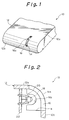
- a diffusing lens 16 is mounted on part, i.e., the end of the casing 12 of a telephone 10 by way of example.
- the casing 12 is formed with a slot 14 from the top 12a to the front 12b thereof.
- the lens 16 in the form of a relatively thick plate is press fitted in the slot 14.
- the lens 16 transmits light in a direction perpendicular to the thicknesswise direction thereof while diffusing it in a predetermined direction.
- the lens 16 has an outer surface 16a which is flush with the outer periphery of the casing 12.
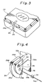
- a notch or recess 16b is formed in the inner periphery of the lens 16 which faces the interior of the casing 12.
- an LED 18 is located in the vicinity of the lens 16 and supported by a support member 20 which is in turn affixed to a printed circuit board 22. The LED 18 is received in the recess 16b of the lens 16.
- the printed circuit board 22 and the support member 20 supported by the circuit board 22 while positioning the lens 16 in the recess 16b have to be accommodated in the limited space of the casing 12. This brings about a drawback that the various parts cannot be freely arranged in the casing 12, as discussed earlier.
- a diffusing lens for an LED embodying the present invention will be described which is mounted on part, i. e., the end of the receiver of a telephone by way of example.
- the receiver has a slot 24 at the end of a casing 12 thereof.
- a diffusing lens 26 in the form of a relatively thick plate is press fitted in the slot 24.
- the lens 26, like the conventional lens, is implemented by a light transmitting member and transmits light while diffusing it in a predetermined direction.
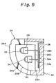
- the lens 26 has an end face or emitting face 26a which is exposed to the outside and flush with the outer periphery of the casing 12. More specifically, when the lens 26 is received in the slot 24, the end face 26a forms part of the outer surface of the casing 12.
- the lens 26 is made up of a relatively thick intermediate plate portion 26A having the end face 26a and opposite relative thick plate portions 26B sandwiching the intermediate portion 26A. Holes 28 and 30 are formed through the lens 26 in the thicknesswise direction for receiving LEDs 32 and 34, respectively.
- a flexible printed circuit board 36 is fixed in place in the casing 12. Leads 32a and 32b and leads 34a and 34b extend out respectively from the LEDs 32 and 34 which are received in the holes 28 and 30. The leads 32a and 32b are drawn out from both ends of the hole 28 and connected to the printed circuit board 36. Likewise, the leads 34a and 34b are drawn out from both ends of the hole 30 and connected to the printed circuit board 36.
- the embodiment uses two LEDs 32 and 34 for simply eliminating the irregular distribution of light.
- the printed circuit board 36 made of a flexible material is affixed to the casing 12 with the end portion 36a thereof facing the rear 26c of the lens 26 with the intermediary of a gap 22a.
- the LEDs 32 and 34 are retained by the diffusing lens 26 and not by the conventional support member 20, FIGS. 1 and 2. Therefore, it is not necessary to provide the casing 12 with a space otherwise occupied by the support member 20.
- the printed circuit board 36 does not have to hold such a support member, it can be provided with a thinner, lighter and mechanically less strong configuration than the conventional one 12. Hence. it is possible to mount the lens 26 even on a miniature receiver.
- the present invention provides a diffusing lens which is formed with a hole for receiving and supporting an LED and, therefore, eliminates the need for an exclusive support member heretofore accommodated in an equipment casing for supporting the LED. This reduces the number of constituent parts and the required space and allows, among others, a printed circuit board to be freely arranged in the casing.
Landscapes
- Engineering & Computer Science (AREA)
- Signal Processing (AREA)
- Physics & Mathematics (AREA)
- General Physics & Mathematics (AREA)
- Optics & Photonics (AREA)
- Microelectronics & Electronic Packaging (AREA)
- Led Device Packages (AREA)
- Telephone Set Structure (AREA)
Claims (11)
- Structure de lentille de diffusion (26) comprenant un élément de transmission de la lumière en forme de plaque relativement épaisse (26A) destinée à transmettre la lumière dans des directions perpendiculaires à l'épaisseur de l'élément (26A) et à diffuser la lumière d'une façon prédéterminée, caractérisée en ce qu'il existe au moins un trou (28) (30) dans l'épaisseur de la lentille (26) et en ce qu'une diode électroluminescente (LED) (32) (34) est maintenue dans le trou (28) (30) par la lentille de diffusion (26).
- Structure selon la revendication 1, dans laquelle la lentille de diffusion (26) est montée sur une partie du boîtier (12) d'un équipement, la partie (26a) de la lentille de diffusion (26) étant exposée à l'extérieur du boîtier (12) et formant une surface émettant de la lumière (26a) qui constitue une partie de la surface du boîtier (12).
- Structure selon la revendication 2, dans laquelle la lentille de diffusion (26) comprend une partie de plaque intermédiaire relativement épaisse (26A) et deux parties de plaque relativement épaisse (26B), chacune étant agencée sur un côté opposé respectif de la partie de plaque intermédiaire (26A), la partie de plaque intermédiaire (26A) étant prise en sandwich entre celles-ci.
- Structure selon la revendication 2, dans laquelle la carte de circuit imprimé (36) est fixée au boîtier (12) et est placée de façon à faire face à l'arrière de la lentille de diffusion (26), et dans laquelle les conducteurs (32a, 32b) (34a, 34b) s'étendent vers l'extérieur de la diode électroluminescente (32) (34) qui est maintenue dans le trou (28) (30) au travers de la lentille (26) et sont reliés à la carte de circuit imprimé (36).
- Structure comprenant une lentille de diffusion en forme de plaque (26) destinée à diffuser la lumière émise à partir d'un dispositif d'émission de lumière (32) (34), et une fente (24) formée à une extrémité d'un boîtier (12) d'un équipement, la lentille (26) étant adaptée dans la fente (24), caractérisé en ce qu'il existe un trou (28) (30) au travers de l'épaisseur de la lentille de diffusion (26) et en ce que le dispositif d'émission de lumière (32) (34) est maintenu dans le trou (28) (30).
- Structure selon la revendication 5, comprenant en outre une carte de circuit imprimé (36) à laquelle au moins deux conducteurs de connexion (32a, 32b) (34a, 34b) du dispositif d'émission de lumière (32) (34) sont reliés électriquement.
- Structure selon la revendication 6, dans laquelle la carte de circuit imprimé (36) est souple.
- Structure selon la revendication 5, dans laquelle le dispositif émetteur de lumière (32) (34) est une diode électroluminescente.
- Structure selon la revendication 5, dans laquelle la surface extérieure (26a) de la lentille de diffusion (26) affleure à la surface extérieure du boîtier (12).
- Procédé de montage d'un dispositif émetteur de lumière (32) (34) dans un boîtier d'équipement (12), comprenant les étapes consistant à former une fente (24) dans une partie du boîtier (12), adapter une lentille de diffusion en forme de plaque (26) dans la fente (24), dans laquelle existe un trou (28) (30) au travers de l'épaisseur de la lentille (26), et introduire le dispositif émetteur de lumière (32) (34) dans le trou (28) (30), le dispositif émetteur de lumière (32) (34) étant maintenu dans le trou (28) (30) par la lentille (26).
- Procédé selon la revendication 10, comprenant en outre l'étape consistant à relier électriquement les conducteurs (32a, 32b) (34a, 34b) du dispositif (32 )(34) à une carte de circuit imprimé souple (36).
Applications Claiming Priority (2)
| Application Number | Priority Date | Filing Date | Title |
|---|---|---|---|
| JP3048902A JP2655452B2 (ja) | 1991-02-21 | 1991-02-21 | 発光ダイオード用拡散レンズ |
| JP48902/91 | 1991-02-21 |
Publications (2)
| Publication Number | Publication Date |
|---|---|
| EP0500331A1 EP0500331A1 (fr) | 1992-08-26 |
| EP0500331B1 true EP0500331B1 (fr) | 1995-11-02 |
Family
ID=12816200
Family Applications (1)
| Application Number | Title | Priority Date | Filing Date |
|---|---|---|---|
| EP92301342A Expired - Lifetime EP0500331B1 (fr) | 1991-02-21 | 1992-02-19 | Structure d'une lentille diffusant la lumière d'une diode électroluminescente |
Country Status (6)
| Country | Link |
|---|---|
| US (1) | US5251117A (fr) |
| EP (1) | EP0500331B1 (fr) |
| JP (1) | JP2655452B2 (fr) |
| AU (1) | AU651430B2 (fr) |
| CA (1) | CA2061479C (fr) |
| ES (1) | ES2079794T3 (fr) |
Families Citing this family (16)
| Publication number | Priority date | Publication date | Assignee | Title |
|---|---|---|---|---|
| US6970434B1 (en) * | 1995-06-07 | 2005-11-29 | Broadcom Corporation | Hierarchical communication system providing intelligent data, program and processing migration |
| US5696636A (en) * | 1995-06-06 | 1997-12-09 | Sun Microsystems, Inc. | Prism to provide visibility of a signal light in two directions |
| DE29711698U1 (de) * | 1997-07-03 | 1997-09-04 | Dosch & Amand GmbH & Co. KG, 81927 München | Kommunikationseinsteckkarte |
| JP2000196719A (ja) * | 1998-12-28 | 2000-07-14 | Matsushita Electric Ind Co Ltd | 携帯用通信機の着信レンズ保持装置 |
| US6238076B1 (en) | 1999-03-29 | 2001-05-29 | Primetech Electronics, Inc. | Compact light mixing and diffusing apparatus |
| US6485160B1 (en) | 2001-06-25 | 2002-11-26 | Gelcore Llc | Led flashlight with lens |
| US6916055B2 (en) | 2002-10-24 | 2005-07-12 | Finisar Corporation | Lens press tool |
| US6811285B2 (en) | 2002-10-24 | 2004-11-02 | Guide Corporation | Method and structure for attaching a lens to a housing in an automotive lighting assembly |
| FR2849562A1 (fr) * | 2002-12-27 | 2004-07-02 | Cellon France Sas | Appareil electronique comportant deux elements structurels et des moyens d'eclairage d'une face externe d'un element structurel |
| WO2007081719A2 (fr) | 2006-01-05 | 2007-07-19 | Illumitex, Inc. | Dispositif optique séparé pour diriger de la lumière depuis une del |
| US8087960B2 (en) | 2006-10-02 | 2012-01-03 | Illumitex, Inc. | LED system and method |
| JP2011512037A (ja) | 2008-02-08 | 2011-04-14 | イルミテックス, インコーポレイテッド | エミッタ層成形のためのシステムおよび方法 |
| JP5220533B2 (ja) * | 2008-09-29 | 2013-06-26 | 株式会社朝日ラバー | レンズ及びそれを用いた光学製品 |
| TW201034256A (en) | 2008-12-11 | 2010-09-16 | Illumitex Inc | Systems and methods for packaging light-emitting diode devices |
| US8449128B2 (en) | 2009-08-20 | 2013-05-28 | Illumitex, Inc. | System and method for a lens and phosphor layer |
| US8585253B2 (en) | 2009-08-20 | 2013-11-19 | Illumitex, Inc. | System and method for color mixing lens array |
Family Cites Families (5)
| Publication number | Priority date | Publication date | Assignee | Title |
|---|---|---|---|---|
| DE2747536A1 (de) * | 1977-10-22 | 1979-04-26 | Diehl Gmbh & Co | Gehaeuse fuer ein elektrisch betriebenes geraet mit einer anzeigeeinrichtung, insbesondere digitalanzeigeeinrichtung |
| CA1299157C (fr) * | 1986-12-19 | 1992-04-21 | Akira Tanaka | Dispositif d'eclairage |
| DE8712960U1 (de) * | 1987-09-25 | 1988-01-07 | Siemens AG, 1000 Berlin und 8000 München | Lichtdurchlässiges Kunststoff-Folienteil zum Schutz von Anzeigeelementen |
| US5001609A (en) * | 1988-10-05 | 1991-03-19 | Hewlett-Packard Company | Nonimaging light source |
| JP2763138B2 (ja) * | 1989-06-23 | 1998-06-11 | 株式会社東芝 | 携帯形情報機器 |
-
1991
- 1991-02-21 JP JP3048902A patent/JP2655452B2/ja not_active Expired - Fee Related
-
1992
- 1992-02-19 CA CA002061479A patent/CA2061479C/fr not_active Expired - Fee Related
- 1992-02-19 ES ES92301342T patent/ES2079794T3/es not_active Expired - Lifetime
- 1992-02-19 EP EP92301342A patent/EP0500331B1/fr not_active Expired - Lifetime
- 1992-02-21 US US07/839,917 patent/US5251117A/en not_active Expired - Fee Related
- 1992-02-21 AU AU11167/92A patent/AU651430B2/en not_active Ceased
Also Published As
| Publication number | Publication date |
|---|---|
| CA2061479A1 (fr) | 1992-08-22 |
| CA2061479C (fr) | 1995-10-17 |
| JPH04267377A (ja) | 1992-09-22 |
| JP2655452B2 (ja) | 1997-09-17 |
| ES2079794T3 (es) | 1996-01-16 |
| AU1116792A (en) | 1992-08-27 |
| EP0500331A1 (fr) | 1992-08-26 |
| US5251117A (en) | 1993-10-05 |
| AU651430B2 (en) | 1994-07-21 |
Similar Documents
| Publication | Publication Date | Title |
|---|---|---|
| EP0500331B1 (fr) | Structure d'une lentille diffusant la lumière d'une diode électroluminescente | |
| US9450631B2 (en) | Case for a hand held device | |
| US5867772A (en) | Cellular telephone assembly and method for assembling a cellular telephone | |
| US5717753A (en) | Switching mat for a telephone or radio handset | |
| CA1289534C (fr) | Dispositif luminescent planar | |
| US20040253977A1 (en) | Speaker supporting device and electronic device comprising this speaker supporting device | |
| JP3248250B2 (ja) | 携帯型無線電話機 | |
| JP4112848B2 (ja) | 携帯電話機におけるスピーカ部の取付構造 | |
| JP2000299723A (ja) | 携帯無線機器の音響部品実装構造 | |
| GB2259205A (en) | Radio pager alerting by vibration | |
| JP2002162550A (ja) | レンズ構造 | |
| US5912968A (en) | Handset unit and assembly method therefore | |
| JPH0545649A (ja) | 液晶表示器の照明構造及び組立構造 | |
| JP4697760B2 (ja) | 電子情報機器 | |
| KR100315676B1 (ko) | 휴대용 무선단말기의 착신램프 장치 | |
| KR102007201B1 (ko) | 엘리베이터용 비상통화장치의 스피커 모듈 | |
| JP4020219B2 (ja) | 表面実装型電磁発音体 | |
| KR100533158B1 (ko) | 이동통신 단말기의 키버튼 장착구조 | |
| JP4116169B2 (ja) | 電磁型発音体 | |
| JP2024148580A (ja) | 照明器具 | |
| KR200430661Y1 (ko) | 광 파이프 기능을 겸비한 페이저 버튼 기구 및 이를이용하는 베이스 세트 | |
| JPH11202813A (ja) | Ledによる表示灯装置およびこの表示灯装置を用いた電気設備機器 | |
| JP3114607B2 (ja) | 通信機器構造 | |
| JP2006222533A (ja) | インターホンのスピーカ固定構造 | |
| JPH06326366A (ja) | 発光ダイオードおよびその取付け構造 |
Legal Events
| Date | Code | Title | Description |
|---|---|---|---|
| PUAI | Public reference made under article 153(3) epc to a published international application that has entered the european phase |
Free format text: ORIGINAL CODE: 0009012 |
|
| 17P | Request for examination filed |
Effective date: 19920313 |
|
| AK | Designated contracting states |
Kind code of ref document: A1 Designated state(s): ES GB IT SE |
|
| 17Q | First examination report despatched |
Effective date: 19940330 |
|
| GRAA | (expected) grant |
Free format text: ORIGINAL CODE: 0009210 |
|
| AK | Designated contracting states |
Kind code of ref document: B1 Designated state(s): ES GB IT SE |
|
| REG | Reference to a national code |
Ref country code: ES Ref legal event code: FG2A Ref document number: 2079794 Country of ref document: ES Kind code of ref document: T3 |
|
| ITF | It: translation for a ep patent filed | ||
| PLBE | No opposition filed within time limit |
Free format text: ORIGINAL CODE: 0009261 |
|
| 26N | No opposition filed | ||
| PGFP | Annual fee paid to national office [announced via postgrant information from national office to epo] |
Ref country code: SE Payment date: 19980205 Year of fee payment: 7 |
|
| PG25 | Lapsed in a contracting state [announced via postgrant information from national office to epo] |
Ref country code: SE Free format text: LAPSE BECAUSE OF NON-PAYMENT OF DUE FEES Effective date: 19990220 |
|
| EUG | Se: european patent has lapsed |
Ref document number: 92301342.9 |
|
| PGFP | Annual fee paid to national office [announced via postgrant information from national office to epo] |
Ref country code: GB Payment date: 20000216 Year of fee payment: 9 |
|
| PGFP | Annual fee paid to national office [announced via postgrant information from national office to epo] |
Ref country code: ES Payment date: 20000218 Year of fee payment: 9 |
|
| PG25 | Lapsed in a contracting state [announced via postgrant information from national office to epo] |
Ref country code: GB Free format text: LAPSE BECAUSE OF NON-PAYMENT OF DUE FEES Effective date: 20010219 |
|
| PG25 | Lapsed in a contracting state [announced via postgrant information from national office to epo] |
Ref country code: ES Free format text: LAPSE BECAUSE OF NON-PAYMENT OF DUE FEES Effective date: 20010220 |
|
| GBPC | Gb: european patent ceased through non-payment of renewal fee |
Effective date: 20010219 |
|
| REG | Reference to a national code |
Ref country code: ES Ref legal event code: FD2A Effective date: 20030203 |
|
| PG25 | Lapsed in a contracting state [announced via postgrant information from national office to epo] |
Ref country code: IT Free format text: LAPSE BECAUSE OF NON-PAYMENT OF DUE FEES Effective date: 20050219 |