EP0500380A1 - Antenne pour fenêtre de véhicule - Google Patents
Antenne pour fenêtre de véhicule Download PDFInfo
- Publication number
- EP0500380A1 EP0500380A1 EP92301432A EP92301432A EP0500380A1 EP 0500380 A1 EP0500380 A1 EP 0500380A1 EP 92301432 A EP92301432 A EP 92301432A EP 92301432 A EP92301432 A EP 92301432A EP 0500380 A1 EP0500380 A1 EP 0500380A1
- Authority
- EP
- European Patent Office
- Prior art keywords
- conducting member
- vehicle window
- window according
- edge
- sheet
- Prior art date
- Legal status (The legal status is an assumption and is not a legal conclusion. Google has not performed a legal analysis and makes no representation as to the accuracy of the status listed.)
- Granted
Links
Images



Classifications
-
- H—ELECTRICITY
- H01—ELECTRIC ELEMENTS
- H01Q—ANTENNAS, i.e. RADIO AERIALS
- H01Q1/00—Details of, or arrangements associated with, antennas
- H01Q1/12—Supports; Mounting means
- H01Q1/1271—Supports; Mounting means for mounting on windscreens
-
- H—ELECTRICITY
- H01—ELECTRIC ELEMENTS
- H01Q—ANTENNAS, i.e. RADIO AERIALS
- H01Q1/00—Details of, or arrangements associated with, antennas
- H01Q1/27—Adaptation for use in or on movable bodies
- H01Q1/32—Adaptation for use in or on road or rail vehicles
Definitions
- the invention relates to an antenna formed on a vehicle window for transmission and/or reception of radio waves particularly, but not exclusively, for a mobile telephone.
- Cellular radio communication is now widely used for mobile telephones in vehicles and it is an object of the present invention to provide an improved antenna on a vehicle window suitable for use with such a mobile vehicle phone.
- a conventional rod aerial externally mounted on a vehicle has two terminals normally connected to a coaxial cable the outer conductor of which provides an earth connection coupled to the vehicle body where the antenna is mounted.
- the present invention provides a vehicle window comprising a sheet for mounting on a vehicle body, said sheet supporting thereon adjacent an edge of the sheet an antenna system for transmission and/or reception of radio waves said antenna system comprising (a) a first conducting member having lateral edges inclined inwardly towards each other to form an apex pointing towards said edge of the sheet and a connection terminal at a position on the first conducting member towards said edge, and (b) a second conducting member electrically insulated from the first conducting member and having a respective connection terminal, said second conducting member being located between the first conducting member and said edge, both said conducting members lying in the plane of said sheet.
- said second conducting member is arranged to form a transmission line with said vehicle body when in situ and thereby form an earth line for the antenna system.
- said first conducting member includes a substantially V-shaped member having the connection terminal at the apex of the V.
- said second conducting member comprises a linear conductor extending substantially parallel to said edge of the sheet.
- said first conducting member has a central axis of symmetry extending substantially perpendicular to said edge of the sheet.
- said second conducting member extends substantially horizontally and said axis of symmetry of the first conducting member extends substantially vertically.
- the angle between said inclined lateral edges is less than 140°, and preferably between 40° and 110°.
- each said inclined lateral edge has a length substantially equal to 1/4 ⁇ where ⁇ is the wave length of the radio wave to be transmitted and received.
- said second conducting member comprises a linear conductor having a length of (1/4 + n/2) ⁇ , where n is an integer, on one or both sides of said connection terminal of the second conducting member. n may have a different integer value on the two sides of the connection terminal.
- Each of these examples provides an antenna suitable for use with a cellular radio phone, the antenna comprising first and second conducting members 11 and 12 supported on a transparent glass sheet 13 for mounting on a vehicle body 14.
- the antenna may be printed or otherwise formed on the glass sheet so that the conducting members 11 and 12 lie effectively in the plane of the sheet which may be flat or curved.
- the conducting members may be applied to an inner surface of glass in a laminate window or alternatively and more usually they may be formed on an external glass surface of a laminate or a monolith sheet. They may also be covered by an electrically insulating sheet such as a plastic film which may be transparent or opaque. Alternatively a nonconductive substance may be printed or painted over otherwise accessible parts of the conducting members.
- the first conducting member 11 has lateral edges 15 and 16 which are inclined inwardly towards each other to form an apex 17 pointing towards an edge 18 of the sheet 13.
- a first connection terminal 19 is provided on the first conducting member at a position towards the edge 18 of the sheet 13.
- the second conducting member 12 is electrically insulated from the first conducting member 11 and has a connection terminal 20.
- the second conducting member 12 is located between the first conducting member 11 and the edge 18 of the glass sheet 13.
- the first conducting member 11 is V-shaped so that the lateral edges 15 and 16 are provided by two inclined arms of the V.
- the conductor may be formed from wire or conductive tracks which each have a width of typically 2 mm.
- the length of the two arms 15 and 16 are each one quarter the wavelength of the radio waves used in the cellular system.
- the V has a central axis of symmetry between the two arms 15 and 16, the axis of symmetry being perpendicular to the edge 18 of the sheet 13 and vertical when in situ in a vehicle body.
- the angle between the two arms 15 and 16 is preferably less than 140° and more preferably between 40° and 110°. 90° provides a particularly effective embodiment.
- the second conducting member 12 comprises a straight linear track of conducting material having a width between 5 and 20 mm. It is printed on the glass close to and parallel to the edge 18 of the glass sheet. This track may be hidden behind a fade-in band on the glass.
- the track 12 extends horizontally and is symmetrically located relative to the apex 17 of the V-shaped conductor. In this way a connection terminal 20 is centrally provided on the track 12 so that the connector 20 is close to but electrically insulated from the connection terminal 19 on the V conductor.
- the track 12 extends equally on both sides of the connection terminal 20 and the length of projection of each half of the track 12 is (1/4 + n/2) ⁇ where ⁇ is the wavelength of the radio waves used and n is an integer.
- the track extends symmetrically on either side of the apex of the V-shaped conductor the track 12 may be arranged to extend on one side only or unequally on both sides provided the extension on each side meets the requirement of being (1/4 + n/2) ⁇ .
- the angle between each of the arms 15 and 16 and the horizontal track 12 may be adjusted to suit the particular application and is usually greater than 20° and preferably between 35° and 70°. 60° is a particularly good example. As this angle is increased the greatest bandwidth is obtained at a progressively increasing impedance.
- the angle chosen at any specific location on a vehicle will be such as to obtain the best bandwidth to, typically 50 , coaxial cable.
- the track 12 may be 100 mm in length or 300 mm in length so that the system is particularly useful for a 900 MHz cell phone frequency.
- the track 12 is spaced a short distance from the edge 18 of the glass sheet and acts as an electrical transmission line between itself and the adjacent metal bodywork of the vehicle.
- the outer braid of a coaxial cable is connected to the connection terminal 20 and the inner line of the coaxial cable is connected to the connection terminal 19.
- the transmission line formed by the track 12 acts as an open circuit at its outer ends and thereby forms an effective short circuit between the track 12 and the adjacent vehicle bodywork 14 adjacent the connection terminal 20. This has the same effect as connecting the outer braid of the coaxial cable to the bodywork 14 and thereby providing an earth part.
- the coaxial cable used with the example of Figure 1 is 50 ohm cable and this embodiment provides an improved matching of the antenna impedance with the coaxial cable impedance over a broader band width than usual.
- This improved broad band width performance obtained by the example of Figure 1 is relatively insensitive to the cable routing and positioning due to the effective short circuit provided between the connection point 20 and the car bodywork 14.
- the coaxial cable may be connected to the connection terminals 19 and 20 by splitting the cable core and braid close to the connection points or alternatively suitable connecting devices may be mounted on the glass so that the connector devices are coupled to the terminals 19 and 20.
- Such connectors may be secured to the glass by adhesive and electrical connections with the terminals 19, 20 and coaxial cable may be formed by soldering or spring-loaded connections.
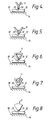
- first and second conducting members forming an antenna in accordance with the invention are shown in Figures 4 to 11.
- Each of these examples includes a first conducting member 11 having the inclined lateral edges referred to above as well as a second conducting member 12 located between the first conducting member and the car body.
- Like reference numerals have been used for parts corresponding to those of Figure 1.
- the V-shaped conducting member has added vertical or horizontal arms.
- the inclined lateral edges of the conductor are formed by a segment of a circular conducting member.
- the track 12 is an extended track parallel to the edge 18 of the window but the upper edges of the track are inclined so that the track is outwardly flared on moving away from the centre connection terminal 20.
- the second conducting member 12 has a short horizontal middle section 25 and upwardly inclined outer sections 26 and 27.
- the second conducting member is in the form of a second V-shaped member 28.
- the second V-shaped member is located between the first conducting member and the edge 18 having its axis of symmetry aligned vertically with that of the first conducting member 11.
- the two apexes are arranged face to face but electrically insulated from each other, each having respective connection terminals 19 and 20. This embodiment extends further into the glass window 13 than those embodiments having a linear track 12.
- connection terminal 19 is provided on the first conducting member at a position nearest the edge 18 of the sheet 13 so that the first conducting member extends away from the terminal 19 in a direction away from the edge 18.
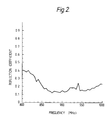
- the reflection coefficient for two antennae of the type shown in Figure 1 in different positions in a vehicle window are shown in Figures 2 and 3.
- the reflection coefficient is shown for a range of frequencies and it can be seen that the reflection coefficient is reduced showing improved matching with the connecting cable over a broad bandwidth, such as 850 MHz to 980MHz, relevant to the cellular radio system used for a vehicle telephone.
- the antenna may be formed in any window such as a windscreen, backlite, sidelite, quarterlite, sixthlite or rooflite of a vehicle.
- the antenna may alternatively be used for reception of radio signals other than mobile telephones, such as television signals.
Landscapes
- Details Of Aerials (AREA)
- Support Of Aerials (AREA)
Applications Claiming Priority (2)
| Application Number | Priority Date | Filing Date | Title |
|---|---|---|---|
| GB919103737A GB9103737D0 (en) | 1991-02-22 | 1991-02-22 | Antenna for vehicle window |
| GB9103737 | 1991-02-22 |
Publications (2)
| Publication Number | Publication Date |
|---|---|
| EP0500380A1 true EP0500380A1 (fr) | 1992-08-26 |
| EP0500380B1 EP0500380B1 (fr) | 1996-05-01 |
Family
ID=10690410
Family Applications (1)
| Application Number | Title | Priority Date | Filing Date |
|---|---|---|---|
| EP92301432A Expired - Lifetime EP0500380B1 (fr) | 1991-02-22 | 1992-02-21 | Antenne pour fenêtre de véhicule |
Country Status (8)
| Country | Link |
|---|---|
| US (1) | US5255002A (fr) |
| EP (1) | EP0500380B1 (fr) |
| JP (1) | JP3322900B2 (fr) |
| KR (1) | KR920017296A (fr) |
| AU (1) | AU642807B2 (fr) |
| DE (1) | DE69210281T2 (fr) |
| GB (1) | GB9103737D0 (fr) |
| ZA (1) | ZA921064B (fr) |
Cited By (13)
| Publication number | Priority date | Publication date | Assignee | Title |
|---|---|---|---|---|
| EP0557794A1 (fr) * | 1992-02-26 | 1993-09-01 | Flachglas Aktiengesellschaft | Antenne de vitre montée dans l'ouverture d'une carrosserie métallique d'un véhicule automobile |
| EP0568284A1 (fr) * | 1992-04-30 | 1993-11-03 | Pilkington Plc | Antenne pour fenêtre de véhicule |
| DE4237818A1 (de) * | 1992-11-10 | 1994-05-19 | Ver Glaswerke Gmbh | Scheibenantenne für Kraftfahrzeuge |
| WO1995003640A1 (fr) * | 1993-07-21 | 1995-02-02 | Richard Hirschmann Gmbh & Co. | Systeme d'antenne |
| WO1996017399A1 (fr) * | 1994-12-01 | 1996-06-06 | Glass Antennas Technology Limited | Systeme d'antenne pour fenetre de vehicule |
| EP0720249A3 (fr) * | 1994-12-27 | 1996-10-02 | Ppg Industries Inc | Antenne de vitrage pour véhicule automobile |
| EP0808518A4 (fr) * | 1995-02-06 | 2001-02-28 | Megawave Corp | Antennes de television |
| EP1079460A3 (fr) * | 1999-08-23 | 2002-05-15 | Nippon Sheet Glass Co., Ltd. | Dispositif d'antenne de vitre |
| WO2004082072A1 (fr) * | 2003-03-13 | 2004-09-23 | Kathrein-Werke Kg | Antenne multibande a capacite terminale |
| WO2005055368A1 (fr) * | 2003-11-21 | 2005-06-16 | Artimi Ltd | Antenne a bande ultralarge |
| US7501988B2 (en) | 2004-07-02 | 2009-03-10 | Volkswagen Aktiengesellschaft | Antenna device for a motor vehicle and the respective motor vehicle |
| US9478872B2 (en) | 2011-10-07 | 2016-10-25 | 3D-Radar As | Ground penetrating radar antenna |
| US9843101B2 (en) | 2014-01-30 | 2017-12-12 | 3D-Radar As | Antenna system for ground penetrating radar |
Families Citing this family (34)
| Publication number | Priority date | Publication date | Assignee | Title |
|---|---|---|---|---|
| US5521606A (en) * | 1992-02-05 | 1996-05-28 | Nippon Sheet Glass Co., Ltd. | Window glass antenna for motor vehicles |
| US5568156A (en) * | 1992-10-09 | 1996-10-22 | Asahi Glass Company Ltd. | High frequency wave glass antenna for an automobile |
| US6008766A (en) * | 1992-11-27 | 1999-12-28 | Nippon Sheet Glass Co., Ltd. | Rear window glass antenna for automobiles |
| US5657029A (en) * | 1993-02-09 | 1997-08-12 | Nippon Sheet Glass Co., Ltd. | Glass antenna device for automobile telephone |
| JPH0746016A (ja) * | 1993-07-30 | 1995-02-14 | Nippon Sheet Glass Co Ltd | 自動車電話用窓ガラスアンテナ |
| EP0808517A4 (fr) * | 1995-02-06 | 1998-05-13 | Megawave Corp | Antenne pour verre de fenetre |
| USD388097S (en) * | 1996-02-05 | 1997-12-23 | Harada Industry Co., Ltd. | Antenna for an automobile |
| USD388096S (en) * | 1996-02-05 | 1997-12-23 | Harada Industry Co., Ltd. | Antenna for an automobile |
| USD388098S (en) * | 1996-02-05 | 1997-12-23 | Harada Industry Co., Ltd. | Antenna for an automobile |
| USD388099S (en) * | 1996-02-05 | 1997-12-23 | Harada Industry Co., Ltd. | Antenna for an automobile |
| DE29925006U1 (de) | 1999-09-20 | 2008-04-03 | Fractus, S.A. | Mehrebenenantenne |
| ES2205898T3 (es) | 1999-10-26 | 2004-05-01 | Fractus, S.A. | Agrupaciones multibanda de antenas entrelazadas. |
| CN100373693C (zh) | 2000-01-19 | 2008-03-05 | 弗拉克托斯股份有限公司 | 空间填充小型天线 |
| EP1313166B1 (fr) | 2000-04-19 | 2007-11-14 | Advanced Automotive Antennas, S.L. | Antenne avancee multiniveau pour vehicules moteur |
| US7511675B2 (en) * | 2000-10-26 | 2009-03-31 | Advanced Automotive Antennas, S.L. | Antenna system for a motor vehicle |
| EP1358696A1 (fr) | 2001-02-07 | 2003-11-05 | Fractus, S.A. | Antenne a plaques en microruban circulaire a large bande miniature |
| CN1507673A (zh) * | 2001-04-16 | 2004-06-23 | �����ɷ� | 双频带双极化天线阵列 |
| WO2003034545A1 (fr) * | 2001-10-16 | 2003-04-24 | Fractus, S.A. | Antenne a plaque microruban multifrequence avec elements couples non alimentes |
| WO2003034544A1 (fr) | 2001-10-16 | 2003-04-24 | Fractus, S.A. | Antenne multibande |
| EP1444751B1 (fr) * | 2001-10-16 | 2007-06-13 | Fractus, S.A. | Antenne chargee. |
| US9755314B2 (en) | 2001-10-16 | 2017-09-05 | Fractus S.A. | Loaded antenna |
| DE20202334U1 (de) | 2002-02-14 | 2002-06-06 | FUBA Automotive GmbH & Co. KG, 31162 Bad Salzdetfurth | Kraftfahrzeugantennen |
| JP2004328694A (ja) * | 2002-11-27 | 2004-11-18 | Taiyo Yuden Co Ltd | アンテナ及び無線通信カード |
| JP4170828B2 (ja) * | 2002-11-27 | 2008-10-22 | 太陽誘電株式会社 | アンテナ及びアンテナ用誘電体基板 |
| JP2004328693A (ja) * | 2002-11-27 | 2004-11-18 | Taiyo Yuden Co Ltd | アンテナ及びアンテナ用誘電体基板 |
| JP2004328703A (ja) * | 2002-11-27 | 2004-11-18 | Taiyo Yuden Co Ltd | アンテナ |
| AU2003252503A1 (en) * | 2002-11-27 | 2004-06-18 | Taiyoyuden Co., Ltd. | Antenna, dielectric substrate for antenna, radio communication card |
| JP2004318466A (ja) * | 2003-04-16 | 2004-11-11 | Matsushita Electric Ind Co Ltd | 商品券、商品券発行システム及び商品券利用システム |
| US7612727B2 (en) * | 2005-12-29 | 2009-11-03 | Exatec, Llc | Antenna for plastic window panel |
| US7589675B2 (en) | 2006-05-19 | 2009-09-15 | Industrial Technology Research Institute | Broadband antenna |
| US8738103B2 (en) | 2006-07-18 | 2014-05-27 | Fractus, S.A. | Multiple-body-configuration multimedia and smartphone multifunction wireless devices |
| US20100201584A1 (en) * | 2009-02-09 | 2010-08-12 | Gm Global Technology Operations, Inc. | Method for automobile roof edge mounted antenna pattern control using a finite frequency selective surface |
| US10243251B2 (en) * | 2015-07-31 | 2019-03-26 | Agc Automotive Americas R&D, Inc. | Multi-band antenna for a window assembly |
| CN105552534B (zh) * | 2016-02-03 | 2019-04-02 | 青勇 | 一种v形天线结构 |
Citations (3)
| Publication number | Priority date | Publication date | Assignee | Title |
|---|---|---|---|---|
| GB2180695A (en) * | 1985-09-21 | 1987-04-01 | Nippon Sheet Glass Co Ltd | A window antenna for a vehicle |
| DE3738226A1 (de) * | 1987-11-11 | 1989-05-24 | Bosch Gmbh Robert | Fahrzeug-scheibenantenne |
| EP0353378A1 (fr) * | 1988-07-19 | 1990-02-07 | Robert Bosch Gmbh | Antenne de vitre pour véhicule |
Family Cites Families (3)
| Publication number | Priority date | Publication date | Assignee | Title |
|---|---|---|---|---|
| DE353378C (de) * | 1920-07-06 | 1922-05-16 | Bruno Raettig | Elektrische Kraftsteckdose |
| DE2336320A1 (de) * | 1973-07-17 | 1975-02-06 | Hans Heinrich Prof Dr Meinke | Empfangsantenne fuer kraftfahrzeuge |
| JPS6281101A (ja) * | 1985-10-03 | 1987-04-14 | Asahi Glass Co Ltd | 自動車のダイバ−シテイ−アンテナ装置 |
-
1991
- 1991-02-22 GB GB919103737A patent/GB9103737D0/en active Pending
-
1992
- 1992-02-12 US US07/834,355 patent/US5255002A/en not_active Expired - Lifetime
- 1992-02-13 ZA ZA921064A patent/ZA921064B/xx unknown
- 1992-02-14 AU AU10960/92A patent/AU642807B2/en not_active Ceased
- 1992-02-21 EP EP92301432A patent/EP0500380B1/fr not_active Expired - Lifetime
- 1992-02-21 DE DE69210281T patent/DE69210281T2/de not_active Expired - Lifetime
- 1992-02-21 KR KR1019920002703A patent/KR920017296A/ko not_active Ceased
- 1992-02-21 JP JP03521092A patent/JP3322900B2/ja not_active Expired - Fee Related
Patent Citations (3)
| Publication number | Priority date | Publication date | Assignee | Title |
|---|---|---|---|---|
| GB2180695A (en) * | 1985-09-21 | 1987-04-01 | Nippon Sheet Glass Co Ltd | A window antenna for a vehicle |
| DE3738226A1 (de) * | 1987-11-11 | 1989-05-24 | Bosch Gmbh Robert | Fahrzeug-scheibenantenne |
| EP0353378A1 (fr) * | 1988-07-19 | 1990-02-07 | Robert Bosch Gmbh | Antenne de vitre pour véhicule |
Non-Patent Citations (1)
| Title |
|---|
| PATENT ABSTRACTS OF JAPAN & JP-A-62 081 101 ( ASAHI GLASS ) 14 April 1987 * |
Cited By (20)
| Publication number | Priority date | Publication date | Assignee | Title |
|---|---|---|---|---|
| EP0557794A1 (fr) * | 1992-02-26 | 1993-09-01 | Flachglas Aktiengesellschaft | Antenne de vitre montée dans l'ouverture d'une carrosserie métallique d'un véhicule automobile |
| US5418543A (en) * | 1992-04-30 | 1995-05-23 | Pilkington Plc | Antenna for vehicle window |
| EP0568284A1 (fr) * | 1992-04-30 | 1993-11-03 | Pilkington Plc | Antenne pour fenêtre de véhicule |
| AU664079B2 (en) * | 1992-04-30 | 1995-11-02 | Pilkington Plc | Antenna for vehicle window |
| DE4237818C3 (de) * | 1992-11-10 | 2000-12-14 | Sekurit Saint Gobain Deutsch | Scheibenantenne für Kraftfahrzeuge |
| DE4237818A1 (de) * | 1992-11-10 | 1994-05-19 | Ver Glaswerke Gmbh | Scheibenantenne für Kraftfahrzeuge |
| US5793337A (en) * | 1993-07-21 | 1998-08-11 | Richard Hirschmann Gmbh & Company | Antennas disposed on separate ground planes |
| WO1995003640A1 (fr) * | 1993-07-21 | 1995-02-02 | Richard Hirschmann Gmbh & Co. | Systeme d'antenne |
| US6452557B1 (en) | 1994-12-01 | 2002-09-17 | Glass Antennas Technology Limited | Antenna arrangement for a vehicle window |
| WO1996017399A1 (fr) * | 1994-12-01 | 1996-06-06 | Glass Antennas Technology Limited | Systeme d'antenne pour fenetre de vehicule |
| EP0720249A3 (fr) * | 1994-12-27 | 1996-10-02 | Ppg Industries Inc | Antenne de vitrage pour véhicule automobile |
| US5670966A (en) * | 1994-12-27 | 1997-09-23 | Ppg Industries, Inc. | Glass antenna for vehicle window |
| EP0808518A4 (fr) * | 1995-02-06 | 2001-02-28 | Megawave Corp | Antennes de television |
| EP1079460A3 (fr) * | 1999-08-23 | 2002-05-15 | Nippon Sheet Glass Co., Ltd. | Dispositif d'antenne de vitre |
| WO2004082072A1 (fr) * | 2003-03-13 | 2004-09-23 | Kathrein-Werke Kg | Antenne multibande a capacite terminale |
| WO2005055368A1 (fr) * | 2003-11-21 | 2005-06-16 | Artimi Ltd | Antenne a bande ultralarge |
| US7327315B2 (en) | 2003-11-21 | 2008-02-05 | Artimi Ltd. | Ultrawideband antenna |
| US7501988B2 (en) | 2004-07-02 | 2009-03-10 | Volkswagen Aktiengesellschaft | Antenna device for a motor vehicle and the respective motor vehicle |
| US9478872B2 (en) | 2011-10-07 | 2016-10-25 | 3D-Radar As | Ground penetrating radar antenna |
| US9843101B2 (en) | 2014-01-30 | 2017-12-12 | 3D-Radar As | Antenna system for ground penetrating radar |
Also Published As
| Publication number | Publication date |
|---|---|
| EP0500380B1 (fr) | 1996-05-01 |
| AU642807B2 (en) | 1993-10-28 |
| JP3322900B2 (ja) | 2002-09-09 |
| AU1096092A (en) | 1992-08-27 |
| DE69210281D1 (de) | 1996-06-05 |
| JPH0563425A (ja) | 1993-03-12 |
| DE69210281T2 (de) | 1996-10-10 |
| GB9103737D0 (en) | 1991-04-10 |
| ZA921064B (en) | 1992-11-25 |
| US5255002A (en) | 1993-10-19 |
| KR920017296A (ko) | 1992-09-26 |
Similar Documents
| Publication | Publication Date | Title |
|---|---|---|
| US5255002A (en) | Antenna for vehicle window | |
| US5418543A (en) | Antenna for vehicle window | |
| US4658259A (en) | On-glass antenna | |
| US5448250A (en) | Laminar microstrip patch antenna | |
| US4992800A (en) | Windshield mounted antenna assembly | |
| JPH1056317A (ja) | 平坦なアンテナ導体構造部の接触方法 | |
| US5353039A (en) | Vehicle rear window glass antenna for transmission and reception of ultrashort waves | |
| KR20070103689A (ko) | 자동차용 고주파 유리 안테나 및 자동차용의 후부 창유리판 | |
| US9837699B2 (en) | Multi-element window antenna | |
| JP3980172B2 (ja) | 広帯域アンテナ | |
| US7903042B2 (en) | Antenna arrangement and window fitted with this antenna arrangement | |
| USRE33743E (en) | On-glass antenna | |
| JP2000307321A (ja) | 地上デジタルオーディオ放送用二重ループ・マルチバンド受信アンテナ | |
| US5614917A (en) | RF sail pumped tuned antenna | |
| US5497167A (en) | Antenna for mounting on a vehicle window | |
| US7663563B2 (en) | High frequency wave glass antenna for an automobile and window glass sheet for an automobile with the same | |
| US6292150B1 (en) | Glass antenna device | |
| KR20110089827A (ko) | 유리 안테나 및 이를 포함하는 차량용 창유리 | |
| CN212062680U (zh) | 新型板载蓝牙天线 | |
| IE44013B1 (en) | Multiband antenna for windowpanes | |
| KR20110105724A (ko) | 차량용 유리 안테나 및 차량용 창 유리 | |
| JP5867416B2 (ja) | ガラスアンテナ及びそれを備える車両用窓ガラス | |
| JP2002305062A (ja) | コネクタ装置 | |
| JP3199201B2 (ja) | ガラスアンテナ | |
| GB1561742A (en) | Multiband antenna for window panes |
Legal Events
| Date | Code | Title | Description |
|---|---|---|---|
| PUAI | Public reference made under article 153(3) epc to a published international application that has entered the european phase |
Free format text: ORIGINAL CODE: 0009012 |
|
| AK | Designated contracting states |
Kind code of ref document: A1 Designated state(s): BE DE ES FR GB GR IT NL SE |
|
| 17P | Request for examination filed |
Effective date: 19930201 |
|
| 17Q | First examination report despatched |
Effective date: 19941024 |
|
| GRAH | Despatch of communication of intention to grant a patent |
Free format text: ORIGINAL CODE: EPIDOS IGRA |
|
| GRAA | (expected) grant |
Free format text: ORIGINAL CODE: 0009210 |
|
| AK | Designated contracting states |
Kind code of ref document: B1 Designated state(s): BE DE ES FR GB GR IT NL SE |
|
| PG25 | Lapsed in a contracting state [announced via postgrant information from national office to epo] |
Ref country code: BE Effective date: 19960501 Ref country code: GR Free format text: LAPSE BECAUSE OF FAILURE TO SUBMIT A TRANSLATION OF THE DESCRIPTION OR TO PAY THE FEE WITHIN THE PRESCRIBED TIME-LIMIT Effective date: 19960501 Ref country code: ES Free format text: THE PATENT HAS BEEN ANNULLED BY A DECISION OF A NATIONAL AUTHORITY Effective date: 19960501 Ref country code: NL Free format text: LAPSE BECAUSE OF FAILURE TO SUBMIT A TRANSLATION OF THE DESCRIPTION OR TO PAY THE FEE WITHIN THE PRESCRIBED TIME-LIMIT Effective date: 19960501 |
|
| REF | Corresponds to: |
Ref document number: 69210281 Country of ref document: DE Date of ref document: 19960605 |
|
| ET | Fr: translation filed | ||
| ITF | It: translation for a ep patent filed | ||
| PG25 | Lapsed in a contracting state [announced via postgrant information from national office to epo] |
Ref country code: SE Effective date: 19960801 |
|
| NLV1 | Nl: lapsed or annulled due to failure to fulfill the requirements of art. 29p and 29m of the patents act | ||
| PLBE | No opposition filed within time limit |
Free format text: ORIGINAL CODE: 0009261 |
|
| 26N | No opposition filed | ||
| REG | Reference to a national code |
Ref country code: GB Ref legal event code: IF02 |
|
| PGFP | Annual fee paid to national office [announced via postgrant information from national office to epo] |
Ref country code: FR Payment date: 20100223 Year of fee payment: 19 |
|
| PGFP | Annual fee paid to national office [announced via postgrant information from national office to epo] |
Ref country code: DE Payment date: 20100303 Year of fee payment: 19 Ref country code: GB Payment date: 20100202 Year of fee payment: 19 |
|
| PGFP | Annual fee paid to national office [announced via postgrant information from national office to epo] |
Ref country code: IT Payment date: 20110216 Year of fee payment: 20 |
|
| GBPC | Gb: european patent ceased through non-payment of renewal fee |
Effective date: 20110221 |
|
| REG | Reference to a national code |
Ref country code: FR Ref legal event code: ST Effective date: 20111102 |
|
| REG | Reference to a national code |
Ref country code: DE Ref legal event code: R119 Ref document number: 69210281 Country of ref document: DE Effective date: 20110901 |
|
| PG25 | Lapsed in a contracting state [announced via postgrant information from national office to epo] |
Ref country code: FR Free format text: LAPSE BECAUSE OF NON-PAYMENT OF DUE FEES Effective date: 20110228 |
|
| PG25 | Lapsed in a contracting state [announced via postgrant information from national office to epo] |
Ref country code: GB Free format text: LAPSE BECAUSE OF NON-PAYMENT OF DUE FEES Effective date: 20110221 |
|
| PG25 | Lapsed in a contracting state [announced via postgrant information from national office to epo] |
Ref country code: DE Free format text: LAPSE BECAUSE OF NON-PAYMENT OF DUE FEES Effective date: 20110901 |