EP0500449A1 - Mittels eines isolierenden Mantels isolierter Langkörper - Google Patents
Mittels eines isolierenden Mantels isolierter Langkörper Download PDFInfo
- Publication number
- EP0500449A1 EP0500449A1 EP92400424A EP92400424A EP0500449A1 EP 0500449 A1 EP0500449 A1 EP 0500449A1 EP 92400424 A EP92400424 A EP 92400424A EP 92400424 A EP92400424 A EP 92400424A EP 0500449 A1 EP0500449 A1 EP 0500449A1
- Authority
- EP
- European Patent Office
- Prior art keywords
- varnish
- body according
- tape
- envelope
- width
- Prior art date
- Legal status (The legal status is an assumption and is not a legal conclusion. Google has not performed a legal analysis and makes no representation as to the accuracy of the status listed.)
- Granted
Links
- 239000002966 varnish Substances 0.000 claims abstract description 45
- 229920002994 synthetic fiber Polymers 0.000 claims abstract description 7
- 239000004020 conductor Substances 0.000 claims description 23
- 229920001343 polytetrafluoroethylene Polymers 0.000 claims description 11
- 239000004810 polytetrafluoroethylene Substances 0.000 claims description 11
- 238000010438 heat treatment Methods 0.000 claims description 7
- 238000000034 method Methods 0.000 claims description 6
- 239000004642 Polyimide Substances 0.000 claims description 5
- 229920001721 polyimide Polymers 0.000 claims description 5
- 239000004094 surface-active agent Substances 0.000 claims description 5
- 239000000463 material Substances 0.000 claims description 4
- 229920000728 polyester Polymers 0.000 claims description 4
- 238000005245 sintering Methods 0.000 claims description 4
- 239000000126 substance Substances 0.000 claims description 3
- 239000004677 Nylon Substances 0.000 claims description 2
- 239000007864 aqueous solution Substances 0.000 claims description 2
- 229920001778 nylon Polymers 0.000 claims description 2
- 239000003989 dielectric material Substances 0.000 claims 1
- 238000007598 dipping method Methods 0.000 claims 1
- 239000004814 polyurethane Substances 0.000 claims 1
- 229920002635 polyurethane Polymers 0.000 claims 1
- 238000009413 insulation Methods 0.000 description 7
- 239000011248 coating agent Substances 0.000 description 6
- 238000000576 coating method Methods 0.000 description 6
- 239000010410 layer Substances 0.000 description 6
- 238000004519 manufacturing process Methods 0.000 description 4
- 238000009422 external insulation Methods 0.000 description 3
- 238000011084 recovery Methods 0.000 description 2
- 238000004804 winding Methods 0.000 description 2
- 239000004972 Polyurethane varnish Substances 0.000 description 1
- 239000013543 active substance Substances 0.000 description 1
- 230000016571 aggressive behavior Effects 0.000 description 1
- 239000002131 composite material Substances 0.000 description 1
- 238000007796 conventional method Methods 0.000 description 1
- 229920001577 copolymer Polymers 0.000 description 1
- 239000006185 dispersion Substances 0.000 description 1
- 238000005516 engineering process Methods 0.000 description 1
- HQQADJVZYDDRJT-UHFFFAOYSA-N ethene;prop-1-ene Chemical group C=C.CC=C HQQADJVZYDDRJT-UHFFFAOYSA-N 0.000 description 1
- 238000001125 extrusion Methods 0.000 description 1
- 239000000835 fiber Substances 0.000 description 1
- 238000011049 filling Methods 0.000 description 1
- 239000011810 insulating material Substances 0.000 description 1
- 239000007788 liquid Substances 0.000 description 1
- 230000004048 modification Effects 0.000 description 1
- 238000012986 modification Methods 0.000 description 1
- 229920003223 poly(pyromellitimide-1,4-diphenyl ether) Polymers 0.000 description 1
- -1 polytetrafluoroethylene Polymers 0.000 description 1
- 239000011241 protective layer Substances 0.000 description 1
- 238000010791 quenching Methods 0.000 description 1
- 230000000171 quenching effect Effects 0.000 description 1
- 238000002791 soaking Methods 0.000 description 1
- 239000002904 solvent Substances 0.000 description 1
Images

Classifications
-
- H—ELECTRICITY
- H01—ELECTRIC ELEMENTS
- H01B—CABLES; CONDUCTORS; INSULATORS; SELECTION OF MATERIALS FOR THEIR CONDUCTIVE, INSULATING OR DIELECTRIC PROPERTIES
- H01B13/00—Apparatus or processes specially adapted for manufacturing conductors or cables
- H01B13/06—Insulating conductors or cables
- H01B13/16—Insulating conductors or cables by passing through or dipping in a liquid bath; by spraying
-
- H—ELECTRICITY
- H01—ELECTRIC ELEMENTS
- H01B—CABLES; CONDUCTORS; INSULATORS; SELECTION OF MATERIALS FOR THEIR CONDUCTIVE, INSULATING OR DIELECTRIC PROPERTIES
- H01B13/00—Apparatus or processes specially adapted for manufacturing conductors or cables
- H01B13/06—Insulating conductors or cables
- H01B13/08—Insulating conductors or cables by winding
- H01B13/0891—After-treatment
-
- H—ELECTRICITY
- H01—ELECTRIC ELEMENTS
- H01B—CABLES; CONDUCTORS; INSULATORS; SELECTION OF MATERIALS FOR THEIR CONDUCTIVE, INSULATING OR DIELECTRIC PROPERTIES
- H01B7/00—Insulated conductors or cables characterised by their form
- H01B7/02—Disposition of insulation
- H01B7/0241—Disposition of insulation comprising one or more helical wrapped layers of insulation
- H01B7/025—Disposition of insulation comprising one or more helical wrapped layers of insulation comprising in addition one or more other layers of non-helical wrapped insulation
Definitions
- the present invention relates to an elongated body insulated by means of an envelope made of an insulating material.
- An elongated body is any body of great length in front of its diameter.
- elongated bodies are qualified as electrical conductors or cables of all kinds, hollow profile bars, tubes, pipes, or more generally pipelines.
- the present invention relates in particular to the insulation of cables or electrical conductors. We will focus in the following on the case of electrical conductors.
- Patent application FR-2 119 939 reports an electrical conductor insulated by means of a taping with an overlap rate at least equal to 50% of a tape made of a synthetic material. This tape is then covered with a varnish of a dried and hardened synthetic material.
- the preferential recovery rates indicated in this document lead in practice to making so-called “overlapping” or “ribbed” tapes. The presence of these overlaps results in an irregularity in the radial thickness of the conductor; therefore, a smooth exterior surface cannot be obtained.
- the object of the present invention is therefore to mark out an elongated body with tape insulation having a smooth external appearance.
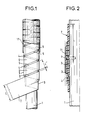
- the present invention provides for this purpose an elongated body insulated by means of an insulating envelope, said envelope consisting of a tape of synthetic material tape around said body, and covered with a layer of varnish of a synthetic material, characterized in that the taping is such that there is a groove between the free edge of any part of the coil not covered by the following turns and the surface not covered with the preceding coil, the width of said groove being substantially between 0 and 5 % of the width of said ribbon, and strictly greater than zero.
- the grooves have a width substantially equal to 1% of that of the ribbon. This value allows the varnish to hang well in the grooves before coating the ribbon.
- the layer of varnish can be deposited by soaking in a bath containing the varnish, then undergoing a heat treatment, such as sintering, intended to remove the volatile substances contained in the varnish and to cook the latter.
- the varnish contains suitable surfactants allowing it, before heat treatment, to hang on the surface which it covers.
- the layer of varnish can also be deposited by an electrostatic process or by a fluidized bed process.
- the invention can be applied for example to the external insulation of electric cables, electric conductors, tubes, pipes, or conduits.
- the electric cables, electric conductors, tubes, pipes, conduits or bars of hollow profiles thus obtained have a smooth external surface and a concentricity greater than 90%.
- the conductor 7 thus obtained is coated with varnish in a varnishing oven 8 (see FIG. 3).
- the varnishing is carried out in three passes P i , P 2 and P 3 .
- the conductor 7 is dipped in a coating tank 9 containing an aqueous dispersion (or varnish) of polytetrafluoroethylene (PTFE) to which surface-active agents have been added.
- PTFE polytetrafluoroethylene
- surfactants are adapted to the PTFE varnish so that, when the conductor 7 is removed from the tank 9, the still liquid varnish fills the grooves 4 and plies the conductor 7 while hanging on the surface of the conductor and does not "flow” as would happen if the width of the joints was not adapted and if the surface tension created by the surfactants does not was not optimized.
- the conductor 7 coated with the PTFE varnish undergoes, in a vertical baking tower 10, a heat treatment (or sintering) intended to remove the solvents and to bake the varnish.
- the final wiring wire obtained therefore has an upper layer of varnish 11 coating the tape and inserted into the grooves 4.
- This layer of varnish has a thickness of between 27 and 36 ⁇ .
- the wiring wire has, thanks to the coating of varnish and the presence of thin gaps, a smooth exterior appearance offering no point of attack for mechanical forces which could give rise to tearing or tearing of the insulating envelope, and a good concentricity characteristic of the strips, that is to say greater than 90%.
- the cabling wires according to the invention also have gaps of reduced width allowing the varnish not to slip on the tape and to fill the grooves formed before coating the ribbon to form a smooth envelope.
- the manufacture of the wiring wires according to the invention does not involve any complex modification of conventional technologies. Indeed, a conventional tape tray is used by simply adapting the tape pitch to the desired covering coefficient, and the varnishing is also carried out according to a conventional technique.
- the product obtained is of better quality, and has electrical, chemical and operating voltage characteristics identical to those of the taped or extruded insulation wiring wires of the prior art. In particular, the external insulation obtained is capable of withstanding electrical and mechanical stresses.
- the width of the gap is not necessarily equal to 1% of the width of the ribbon, and it can preferably take any value between 0 and 5% and always strictly greater than 0.
- the varnish may slip on the tape without filling the gaps, even in the presence of tension-active agents. It would then be more difficult to obtain a smooth insulating envelope.
- PTFE tape with a varnish in aqueous solution of ethylene-propylene fluorinated copolymer (FEP) or a polyimide tape (like "KAPTON” - registered trademark) with a polyurethane varnish or polyimide, or finally a polyester tape with a nylon or polyester varnish.
- FEP ethylene-propylene fluorinated copolymer
- polyimide tape like "KAPTON” - registered trademark
- the inventon can be applied to a structure other than that of the wiring wire, such as for example a coaxial cable whose outer insulating envelope consists of a composite tape of polyimide and PTFE and a varnish PTFE or FEP.
- a coaxial cable whose outer insulating envelope consists of a composite tape of polyimide and PTFE and a varnish PTFE or FEP.
- all the pairs of materials mentioned above can also be used to produce the outer envelope of a coaxial cable.
- the invention makes it possible to produce an insulating envelope having all the necessary qualities.
- the invention can be applied to the insulation of any elongated body and in particular to that of cables of all types, including fiber optic cables, electrical conductors of all kinds and possibly pipes, tubes. or pipes whose working environment implies an insulating protection having the qualities of that produced according to the invention.
- the invention can also be applied to the manufacture of hollow profile bars. For this, it suffices to provide the insulation on a support or support body which is removed after manufacture of the shaped profile bar.
- the thickness of the ribbon can be between 50 and 200 ⁇ and its width between 7 and 12 mm.
Landscapes
- Engineering & Computer Science (AREA)
- Manufacturing & Machinery (AREA)
- Insulating Bodies (AREA)
- Decoration Of Textiles (AREA)
- Rigid Pipes And Flexible Pipes (AREA)
- Insulated Conductors (AREA)
- Processes Specially Adapted For Manufacturing Cables (AREA)
Applications Claiming Priority (2)
| Application Number | Priority Date | Filing Date | Title |
|---|---|---|---|
| FR9102161 | 1991-02-22 | ||
| FR9102161A FR2673318A1 (fr) | 1991-02-22 | 1991-02-22 | Procede de realisation d'une enveloppe isolante autour d'un corps allonge, et produit obtenu par ce procede. |
Publications (2)
| Publication Number | Publication Date |
|---|---|
| EP0500449A1 true EP0500449A1 (de) | 1992-08-26 |
| EP0500449B1 EP0500449B1 (de) | 1994-12-07 |
Family
ID=9410006
Family Applications (1)
| Application Number | Title | Priority Date | Filing Date |
|---|---|---|---|
| EP92400424A Expired - Lifetime EP0500449B1 (de) | 1991-02-22 | 1992-02-18 | Mittels eines isolierenden Mantels isolierter Langkörper |
Country Status (6)
| Country | Link |
|---|---|
| US (1) | US5218170A (de) |
| EP (1) | EP0500449B1 (de) |
| JP (1) | JPH0581931A (de) |
| CA (1) | CA2061588C (de) |
| DE (1) | DE69200777T2 (de) |
| FR (1) | FR2673318A1 (de) |
Families Citing this family (10)
| Publication number | Priority date | Publication date | Assignee | Title |
|---|---|---|---|---|
| JPH04296316A (ja) * | 1990-12-18 | 1992-10-20 | General Electric Co <Ge> | 耐熱性樹脂組成物、製品及び方法 |
| FR2686727B1 (fr) * | 1992-01-28 | 1997-01-31 | Filotex Sa | Conducteur electrique et cable electrique contenant un tel conducteur. |
| US5393105A (en) * | 1992-12-24 | 1995-02-28 | Petterson; Bart | Ductwork for delivery of low temperature air |
| US5594230A (en) * | 1993-02-18 | 1997-01-14 | Norand Corporation | Analyzer for bar code readers and decoders |
| DE4323121A1 (de) * | 1993-07-10 | 1995-02-23 | Hoechst Ag | Abriebbeständige Fluorpolymer-Mischungen |
| US5721397A (en) * | 1995-06-07 | 1998-02-24 | Weinberg; Martin J. | Electrical insulation and products protected thereby |
| JP2002170439A (ja) * | 2000-11-30 | 2002-06-14 | Ngk Spark Plug Co Ltd | 耐熱性被覆電線 |
| US7472724B2 (en) * | 2003-08-18 | 2009-01-06 | Electrolock, Inc. | Method and apparatus for creating, using, and dispensing tubes |
| FR2861158B1 (fr) * | 2003-10-17 | 2006-01-27 | Technip France | Conduite tubulaire flexible notamment pour exploitation petroliere, a enroulement de ptfe. |
| US20150167868A1 (en) * | 2013-12-17 | 2015-06-18 | Scott Boncha | Maple sap vacuum collection systems with chew proof tubing |
Citations (5)
| Publication number | Priority date | Publication date | Assignee | Title |
|---|---|---|---|---|
| GB902567A (en) * | 1958-02-06 | 1962-08-01 | Reyrolle A & Co Ltd | Improvements relating to elongated electrical conductors embedded in cast resin solid insulation |
| FR1571555A (de) * | 1967-06-10 | 1969-06-20 | ||
| FR2119939A1 (de) * | 1970-11-25 | 1972-08-11 | British Insulated Callenders | |
| FR2555799A1 (fr) * | 1983-11-25 | 1985-05-31 | Filotex Sa | Cable electrique, notamment pour usage aerospatial, a caracteristiques electriques ameliorees |
| EP0363064A1 (de) * | 1988-10-03 | 1990-04-11 | AT&T Corp. | Isolierungsanordnung für Leiter |
Family Cites Families (10)
| Publication number | Priority date | Publication date | Assignee | Title |
|---|---|---|---|---|
| US1362179A (en) * | 1920-02-03 | 1920-12-14 | Free & Easy Belt Co | Trousers-supporter |
| US3488537A (en) * | 1967-04-04 | 1970-01-06 | Gen Electric | Dynamoelectric machine having fluorocarbon plastic film insulation and method of making the same |
| US3617617A (en) * | 1970-06-12 | 1971-11-02 | Du Pont | Insulated electrical conductor |
| JPS5233100A (en) * | 1975-09-09 | 1977-03-12 | Mitsubishi Electric Corp | Method to manufacture an insulated conductor |
| BE885751Q (fr) * | 1976-08-27 | 1981-02-16 | Kendall & Co | Procede et appareil pour appliquer un liquide moussable sur un objet cylindrique |
| JPS57130304A (en) * | 1981-02-02 | 1982-08-12 | Chiyanpurein Cable Corp | Insulating system for wire or cable |
| US4471022A (en) * | 1981-04-17 | 1984-09-11 | Essex Group, Inc. | Water soluble polyimide, coated wire and method of coating |
| JPS63216209A (ja) * | 1987-03-04 | 1988-09-08 | 株式会社東芝 | 絶縁電線 |
| SE457030B (sv) * | 1987-03-24 | 1988-11-21 | Asea Ab | Elektriskt isolermaterial omfattande ett isolerskikt av en organisk polymer samt anvaendning av isolermaterialet i en haerva. |
| US4851060A (en) * | 1987-08-12 | 1989-07-25 | Essex Group, Inc. | Multilayer wrapped insulated magnet wire |
-
1991
- 1991-02-22 FR FR9102161A patent/FR2673318A1/fr not_active Withdrawn
-
1992
- 1992-02-18 EP EP92400424A patent/EP0500449B1/de not_active Expired - Lifetime
- 1992-02-18 DE DE69200777T patent/DE69200777T2/de not_active Expired - Fee Related
- 1992-02-20 CA CA002061588A patent/CA2061588C/fr not_active Expired - Fee Related
- 1992-02-21 JP JP4035348A patent/JPH0581931A/ja active Pending
- 1992-02-21 US US07/839,130 patent/US5218170A/en not_active Expired - Fee Related
Patent Citations (5)
| Publication number | Priority date | Publication date | Assignee | Title |
|---|---|---|---|---|
| GB902567A (en) * | 1958-02-06 | 1962-08-01 | Reyrolle A & Co Ltd | Improvements relating to elongated electrical conductors embedded in cast resin solid insulation |
| FR1571555A (de) * | 1967-06-10 | 1969-06-20 | ||
| FR2119939A1 (de) * | 1970-11-25 | 1972-08-11 | British Insulated Callenders | |
| FR2555799A1 (fr) * | 1983-11-25 | 1985-05-31 | Filotex Sa | Cable electrique, notamment pour usage aerospatial, a caracteristiques electriques ameliorees |
| EP0363064A1 (de) * | 1988-10-03 | 1990-04-11 | AT&T Corp. | Isolierungsanordnung für Leiter |
Also Published As
| Publication number | Publication date |
|---|---|
| CA2061588A1 (fr) | 1992-08-23 |
| EP0500449B1 (de) | 1994-12-07 |
| DE69200777D1 (de) | 1995-01-19 |
| JPH0581931A (ja) | 1993-04-02 |
| DE69200777T2 (de) | 1995-04-13 |
| US5218170A (en) | 1993-06-08 |
| CA2061588C (fr) | 1998-12-29 |
| FR2673318A1 (fr) | 1992-08-28 |
Similar Documents
| Publication | Publication Date | Title |
|---|---|---|
| EP0964408B1 (de) | Informationsübertragungskabel und sein Herstellungsverfahren | |
| EP0704735B1 (de) | Elektrischer Isolator mit optischen Fasern und zugehöriges Herstellungsverfahren | |
| EP0696750B1 (de) | Herstellungsverfahren für ein verstärktes faseroptisches Kabel, zugehörige Vorrichtung und Kabel mittels diesem Verfahren gefertigt | |
| FR2908895A1 (fr) | Cables lisses et multilignes a rapport resistance/poids eleve | |
| CA1137284A (fr) | Procede de fabrication d'un element isolant comportant une portion centrale entouree d'une pluralite d'ailettes, et element isolant obtenu par ce procede | |
| EP0500449B1 (de) | Mittels eines isolierenden Mantels isolierter Langkörper | |
| FR2693828A1 (fr) | Câble pour signaux comportant un écran en polymère recouvert de métal. | |
| BE898104R (fr) | Cable à fibres optiques. | |
| CA2088215C (fr) | Cable electrique haute frequence | |
| FR2728694A1 (fr) | Module pour cables a fibres optiques, procede de fabrication et installation a cet effet | |
| CA1189584A (fr) | Cable de telecommande a element central textile positionne | |
| EP0311941B1 (de) | Fabrikationsverfahren für ein optisches Kabel und danach hergestelltes Kabel | |
| EP0568415B1 (de) | Isolierungsverfahren eines elektrischen Leiters und isolierter elektrischer Daht hergestellt nach diesem Verfahren | |
| EP0294256A1 (de) | Elektrisches Kabel zur Übertragung von Starkstrom und Steuerstrom | |
| EP1037216B1 (de) | Telekomkabelherstellung mit Metalldrahtgruppen mit verschiedenen Schlägen | |
| FR2584057A1 (fr) | Procede de fabrication d'un objet avec un materiau composite. | |
| EP0893803B1 (de) | Elektrisch leitender Draht | |
| FR2491511A1 (fr) | Toron compose de plusieurs fils et procede pour sa fabrication | |
| FR3144386A1 (fr) | Câble blindé électrique | |
| FR2745116A1 (fr) | Cable electrique blinde et procede de fabrication d'un tel cable | |
| BE898103A (fr) | Cable à fibres optiques. | |
| EP0141723A2 (de) | Herstellungsverfahren für ein faseroptisches Kabel ohne elektrisch leitende Materialien | |
| EP1177562A1 (de) | Tiefpasskabel | |
| EP0953990A1 (de) | Elektrischer Draht und Verfahren zu seiner Herstellung | |
| FR3110765A1 (fr) | câble présentant une résistance à la corrosion améliorée |
Legal Events
| Date | Code | Title | Description |
|---|---|---|---|
| PUAI | Public reference made under article 153(3) epc to a published international application that has entered the european phase |
Free format text: ORIGINAL CODE: 0009012 |
|
| AK | Designated contracting states |
Kind code of ref document: A1 Designated state(s): DE FR GB IT |
|
| 17P | Request for examination filed |
Effective date: 19921117 |
|
| 17Q | First examination report despatched |
Effective date: 19940325 |
|
| GRAA | (expected) grant |
Free format text: ORIGINAL CODE: 0009210 |
|
| AK | Designated contracting states |
Kind code of ref document: B1 Designated state(s): DE FR GB IT |
|
| REF | Corresponds to: |
Ref document number: 69200777 Country of ref document: DE Date of ref document: 19950119 |
|
| ITF | It: translation for a ep patent filed | ||
| GBT | Gb: translation of ep patent filed (gb section 77(6)(a)/1977) |
Effective date: 19950118 |
|
| PLBE | No opposition filed within time limit |
Free format text: ORIGINAL CODE: 0009261 |
|
| STAA | Information on the status of an ep patent application or granted ep patent |
Free format text: STATUS: NO OPPOSITION FILED WITHIN TIME LIMIT |
|
| 26N | No opposition filed | ||
| PGFP | Annual fee paid to national office [announced via postgrant information from national office to epo] |
Ref country code: GB Payment date: 19990115 Year of fee payment: 8 Ref country code: FR Payment date: 19990115 Year of fee payment: 8 |
|
| PGFP | Annual fee paid to national office [announced via postgrant information from national office to epo] |
Ref country code: DE Payment date: 19990122 Year of fee payment: 8 |
|
| PG25 | Lapsed in a contracting state [announced via postgrant information from national office to epo] |
Ref country code: GB Free format text: LAPSE BECAUSE OF NON-PAYMENT OF DUE FEES Effective date: 20000218 |
|
| GBPC | Gb: european patent ceased through non-payment of renewal fee |
Effective date: 20000218 |
|
| PG25 | Lapsed in a contracting state [announced via postgrant information from national office to epo] |
Ref country code: FR Free format text: LAPSE BECAUSE OF NON-PAYMENT OF DUE FEES Effective date: 20001031 |
|
| PG25 | Lapsed in a contracting state [announced via postgrant information from national office to epo] |
Ref country code: DE Free format text: LAPSE BECAUSE OF NON-PAYMENT OF DUE FEES Effective date: 20001201 |
|
| REG | Reference to a national code |
Ref country code: FR Ref legal event code: ST |
|
| PG25 | Lapsed in a contracting state [announced via postgrant information from national office to epo] |
Ref country code: IT Free format text: LAPSE BECAUSE OF NON-PAYMENT OF DUE FEES;WARNING: LAPSES OF ITALIAN PATENTS WITH EFFECTIVE DATE BEFORE 2007 MAY HAVE OCCURRED AT ANY TIME BEFORE 2007. THE CORRECT EFFECTIVE DATE MAY BE DIFFERENT FROM THE ONE RECORDED. Effective date: 20050218 |