EP0500792B1 - Echangeur thermique - Google Patents
Echangeur thermique Download PDFInfo
- Publication number
- EP0500792B1 EP0500792B1 EP91900646A EP91900646A EP0500792B1 EP 0500792 B1 EP0500792 B1 EP 0500792B1 EP 91900646 A EP91900646 A EP 91900646A EP 91900646 A EP91900646 A EP 91900646A EP 0500792 B1 EP0500792 B1 EP 0500792B1
- Authority
- EP
- European Patent Office
- Prior art keywords
- drum
- section
- scoop
- chamber
- outer drum
- Prior art date
- Legal status (The legal status is an assumption and is not a legal conclusion. Google has not performed a legal analysis and makes no representation as to the accuracy of the status listed.)
- Expired - Lifetime
Links
- 239000000969 carrier Substances 0.000 claims abstract description 85
- 239000000463 material Substances 0.000 claims abstract description 82
- 238000012546 transfer Methods 0.000 claims abstract description 17
- 239000007787 solid Substances 0.000 claims description 61
- 238000001816 cooling Methods 0.000 claims description 34
- 238000010438 heat treatment Methods 0.000 claims description 34
- 239000012530 fluid Substances 0.000 claims description 16
- 239000002245 particle Substances 0.000 claims description 15
- 239000000047 product Substances 0.000 claims description 6
- 238000012545 processing Methods 0.000 claims description 4
- 239000011343 solid material Substances 0.000 claims description 4
- 238000004513 sizing Methods 0.000 claims description 2
- 239000012265 solid product Substances 0.000 claims 2
- 238000007789 sealing Methods 0.000 claims 1
- 238000004140 cleaning Methods 0.000 abstract description 6
- 239000007788 liquid Substances 0.000 description 50
- 239000007789 gas Substances 0.000 description 12
- 238000000034 method Methods 0.000 description 9
- 230000008016 vaporization Effects 0.000 description 7
- 230000005484 gravity Effects 0.000 description 5
- 239000002826 coolant Substances 0.000 description 4
- 230000001473 noxious effect Effects 0.000 description 4
- 238000009834 vaporization Methods 0.000 description 4
- 239000002699 waste material Substances 0.000 description 3
- XLYOFNOQVPJJNP-UHFFFAOYSA-N water Substances O XLYOFNOQVPJJNP-UHFFFAOYSA-N 0.000 description 3
- 229910000831 Steel Inorganic materials 0.000 description 2
- 239000012080 ambient air Substances 0.000 description 2
- 239000000571 coke Substances 0.000 description 2
- 239000012809 cooling fluid Substances 0.000 description 2
- 239000000110 cooling liquid Substances 0.000 description 2
- 239000000428 dust Substances 0.000 description 2
- 239000012188 paraffin wax Substances 0.000 description 2
- 238000005096 rolling process Methods 0.000 description 2
- 239000010959 steel Substances 0.000 description 2
- 239000001993 wax Substances 0.000 description 2
- 241000209527 Arum Species 0.000 description 1
- 239000004215 Carbon black (E152) Substances 0.000 description 1
- 235000006481 Colocasia esculenta Nutrition 0.000 description 1
- 239000002956 ash Substances 0.000 description 1
- 239000006227 byproduct Substances 0.000 description 1
- 230000006835 compression Effects 0.000 description 1
- 238000007906 compression Methods 0.000 description 1
- 238000010276 construction Methods 0.000 description 1
- 238000011109 contamination Methods 0.000 description 1
- 230000000694 effects Effects 0.000 description 1
- 229930195733 hydrocarbon Natural products 0.000 description 1
- 150000002430 hydrocarbons Chemical class 0.000 description 1
- 238000009413 insulation Methods 0.000 description 1
- 230000001788 irregular Effects 0.000 description 1
- 239000011344 liquid material Substances 0.000 description 1
- 238000012423 maintenance Methods 0.000 description 1
- 239000000203 mixture Substances 0.000 description 1
- 238000012986 modification Methods 0.000 description 1
- 230000004048 modification Effects 0.000 description 1
- 238000012856 packing Methods 0.000 description 1
- 231100000614 poison Toxicity 0.000 description 1
- 230000007096 poisonous effect Effects 0.000 description 1
- 230000005855 radiation Effects 0.000 description 1
- 230000003134 recirculating effect Effects 0.000 description 1
- 239000004576 sand Substances 0.000 description 1
- 238000007790 scraping Methods 0.000 description 1
- 239000010802 sludge Substances 0.000 description 1
- 239000004575 stone Substances 0.000 description 1
- 239000011364 vaporized material Substances 0.000 description 1
Images




Classifications
-
- C—CHEMISTRY; METALLURGY
- C10—PETROLEUM, GAS OR COKE INDUSTRIES; TECHNICAL GASES CONTAINING CARBON MONOXIDE; FUELS; LUBRICANTS; PEAT
- C10B—DESTRUCTIVE DISTILLATION OF CARBONACEOUS MATERIALS FOR PRODUCTION OF GAS, COKE, TAR, OR SIMILAR MATERIALS
- C10B1/00—Retorts
- C10B1/10—Rotary retorts
-
- F—MECHANICAL ENGINEERING; LIGHTING; HEATING; WEAPONS; BLASTING
- F27—FURNACES; KILNS; OVENS; RETORTS
- F27B—FURNACES, KILNS, OVENS OR RETORTS IN GENERAL; OPEN SINTERING OR LIKE APPARATUS
- F27B7/00—Rotary-drum furnaces, i.e. horizontal or slightly inclined
-
- F—MECHANICAL ENGINEERING; LIGHTING; HEATING; WEAPONS; BLASTING
- F27—FURNACES; KILNS; OVENS; RETORTS
- F27B—FURNACES, KILNS, OVENS OR RETORTS IN GENERAL; OPEN SINTERING OR LIKE APPARATUS
- F27B7/00—Rotary-drum furnaces, i.e. horizontal or slightly inclined
- F27B7/14—Rotary-drum furnaces, i.e. horizontal or slightly inclined with means for agitating or moving the charge
- F27B7/18—Rotary-drum furnaces, i.e. horizontal or slightly inclined with means for agitating or moving the charge the means being movable within the drum
-
- F—MECHANICAL ENGINEERING; LIGHTING; HEATING; WEAPONS; BLASTING
- F28—HEAT EXCHANGE IN GENERAL
- F28D—HEAT-EXCHANGE APPARATUS, NOT PROVIDED FOR IN ANOTHER SUBCLASS, IN WHICH THE HEAT-EXCHANGE MEDIA DO NOT COME INTO DIRECT CONTACT
- F28D11/00—Heat-exchange apparatus employing moving conduits
- F28D11/02—Heat-exchange apparatus employing moving conduits the movement being rotary, e.g. performed by a drum or roller
- F28D11/04—Heat-exchange apparatus employing moving conduits the movement being rotary, e.g. performed by a drum or roller performed by a tube or a bundle of tubes
-
- F—MECHANICAL ENGINEERING; LIGHTING; HEATING; WEAPONS; BLASTING
- F28—HEAT EXCHANGE IN GENERAL
- F28F—DETAILS OF HEAT-EXCHANGE AND HEAT-TRANSFER APPARATUS, OF GENERAL APPLICATION
- F28F19/00—Preventing the formation of deposits or corrosion, e.g. by using filters or scrapers
- F28F19/008—Preventing the formation of deposits or corrosion, e.g. by using filters or scrapers by using scrapers
Definitions
- the inside of the outer drum and the inside and outside of the inner drum are being cleaned continuously by the carriers and/or helixes that rotate freely with the rotating drums.
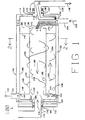
- Drum 102 carries within it a freely rotating helix 166 with an axis parallel to drum 102.
- the helix has a diameter such that it rests on the bottom inside of drum 102 and helixes around the outside of drum 134 but does not touch drum 134.
- Helix 166 is located between rods 140 and 142 and is allowed to rotate freely inside drum 102 as drum 102 rotates in a rotational direction which is the same as the rotational direction of drum 102.
- Freely rotating helix 166 rotates at a greater rounds per unit time than drum 102 because the exterior circumference of helix 166 is smaller than the circumference of the inside wall of drum 102.
- Freely rotating helix 166 is configured to move material which rests on the bottom inside of drum 102 from the front end to the rear end of drum 102.
Landscapes
- Engineering & Computer Science (AREA)
- Mechanical Engineering (AREA)
- General Engineering & Computer Science (AREA)
- Chemical & Material Sciences (AREA)
- Thermal Sciences (AREA)
- Oil, Petroleum & Natural Gas (AREA)
- Physics & Mathematics (AREA)
- Materials Engineering (AREA)
- Organic Chemistry (AREA)
- Vaporization, Distillation, Condensation, Sublimation, And Cold Traps (AREA)
- Separation By Low-Temperature Treatments (AREA)
- Compression-Type Refrigeration Machines With Reversible Cycles (AREA)
- Processing Of Solid Wastes (AREA)
- Heat-Exchange Devices With Radiators And Conduit Assemblies (AREA)
- Power Steering Mechanism (AREA)
Claims (14)
- Appareil de traitement thermique d'une matière, comprenant :un tambour externe pratiquement cylindrique (102) qui peut tourner autour d'un axe pratiquement horizontal et qui a une première extrémité et une seconde extrémité,un tambour interne pratiquement cylindrique (134) placé dans le tambour externe et fixé à l'intérieur du tambour externe afin qu'il en soit solidaire et qu'il tourne avec lui, le tambour interne ayant une première extrémité et une seconde extrémité,un conduit d'entrée (124) disposé afin qu'il permette l'écoulement de la matière à la première extrémité du tambour externe (102),un conduit de sortie (128) placé afin qu'il extraie la matière de la seconde extrémité du tambour externe (102),un conduit de transfert (172, 173) monté afin qu'il transfère la matière de la seconde extrémité du tambour externe à la première extrémité du tambour interne,une première hélice (166) qui tourne librement, placée dans le tambour externe (102) et à la surface interne de la face inférieure de ce tambour, et entourant le tambour interne (134), son axe étant pratiquement parallèle à l'axe du tambour externe, l'hélice étant enroulée afin qu'elle transporte la matière de la première extrémité vers la seconde extrémité du tambour externe,une seconde hélice (168) qui peut tourner librement, disposée dans le tambour interne (134) et à la surface interne de la face inférieure de ce tambour, enroulée afin qu'elle transporte la matière de la première extrémité vers la seconde extrémité du tambour interne, etun organe de chauffage (150) disposé afin qu'il chauffe le tambour externe (102).
- Appareil selon la revendication 1, dans lequel les extrémités du tambour interne (134) se terminent avant les extrémités du tambour externe (102).
- Appareil selon la revendication 1 ou 2, dans lequel le conduit de transfert est perforé afin qu'il filtre les particules relativement petites de la matière et transporte les particules relativement grosses de la matière vers le tambour interne (134).
- Appareil selon i'une quelconque des revendications précédentes, dans lequel le conduit de transfert est un godet (172) monté dans le tambour externe (102) avec une ouverture d'entrée placée entre la seconde extrémité du tambour externe (102) et la première extrémité du tambour interne (134) et adjacente à la surface interne du tambour externe, le godet ayant une ouverture de sortie vers l'intérieur du tambour interne et étant perforé afin qu'il filtre les particules de dimension relativement petite de la matière et transporte les particules relativement grosses de la matière vers le tambour interne.
- Appareil selon la revendication 4, dans lequel le conduit de sortie (128) comporte un godet monté dans le tambour externe (102), et qui comprend un dispositif de classement de particules disposé afin qu'il admette dans le godet des particules de dimension inférieure à une dimension prédéterminée mais qu'il exclue les particules plus grosses, le second godet assurant la communication avec le conduit de sortie.
- Appareil selon l'une quelconque des revendications 1 à 5, comprenant :une chambre cylindrique coaxiale de refroidissement montée sur les extrémité avant et arrière du tambour externe et destinée à tourner avec lui,le conduit de sortie comprenant un conduit (674) de matières solides communiquant avec l'intérieur du tambour externe et l'intérieur d'une chambre arrière parmi les chambres de refroidissement.
- Appareil selon l'une quelconque des revendications précédentes, dans lequel le tambour externe (102) a une ouverture centrale à chaque extrémité,
le ccnduit d'entrée (124) passant par l'ouverture centrale de la première extrémité et le conduit de sortie (128) passant par l'ouverture centrale de la seconde extrémité. - Appareil selon l'une quelconque des revendications 1 à 7, comprenant plusieurs organes de transport mobiles librement dans le tambour externe.
- Appareil selon la revendication 8, dans lequel les organes de transport sont mobiles du tambour externe au tambour interne par l'intermédiaire du conduit de transfert.
- Appareil selon l'une quelconque des revendications précédentes, destiné au traitement thermique d'une matière première contenant des matières solides et des fluides, tel que :le tambour externe (602) comporte une section de chauffage et une section coaxiale de refroidissement aux extrémités avant et arrière de la section de chauffage,le conduit d'entrée comprend un conduit coaxial de matière première (624A) passant dans la section de refroidissement avant pour transmettre la matière première à la section de chauffage, etla première hélice est un transporteur de matière première (766) dans la section de chauffage de manière que la matière première soit déplacée dans la section de chauffage et subisse le traitement thermique assurant la séparation des fluides des matières solides, et l'appareil comporte en outre un conduit coaxial de matière traitée partant de la section de chauffage vers la section arrière de refroidissement et destiné à refroidir et retirer les produits du traitement thermique du tambour.
- Appareil selon la revendication 10, comprenant un joint rotatif assurant l'étanchéité autour de chacun des conduits de matière première et de matière traitée de manière que la communication entre l'intérieur de la section de refroidissement et l'extérieur de l'appareil soit évitée.
- Appareil selon la revendication 10 ou 11, comprenant une ouverture formée entre la section de chauffage et la section de refroidissement et destinée au passage des produits en phase vapeur obtenus par traitement thermique de la matière première dans la section de refroidissement afin que les produits en phase vapeur soient refroidis dans le système de refroidissement.
- Appareil selon l'une des revendications 10, 11 et 12, comprenant une ouverture formée entre la section de chauffage et la section de refroidissement et destinée à transmettre les produits solides du traitement thermique de la matière première à la section de refroidissement afin que les produits solides soient refroidis dans la section de refroidissement.
- Appareil selon l'une quelconque des revendications 10 à 13, comprenant en outre un enroulement de circulation de vapeurs placé autour de la section de refroidissement et connecté afin qu'il reçoive les vapeurs de la section de chauffage, qu'il condense les vapeurs et qu'il évacue le condensat à l'extérieur de l'appareil.
Applications Claiming Priority (3)
| Application Number | Priority Date | Filing Date | Title |
|---|---|---|---|
| US430731 | 1982-09-30 | ||
| US43073189A | 1989-11-07 | 1989-11-07 | |
| PCT/US1990/006499 WO1991006615A1 (fr) | 1989-11-02 | 1990-11-02 | Echangeur thermique |
Publications (3)
| Publication Number | Publication Date |
|---|---|
| EP0500792A1 EP0500792A1 (fr) | 1992-09-02 |
| EP0500792A4 EP0500792A4 (en) | 1993-01-13 |
| EP0500792B1 true EP0500792B1 (fr) | 1997-01-22 |
Family
ID=23708793
Family Applications (1)
| Application Number | Title | Priority Date | Filing Date |
|---|---|---|---|
| EP91900646A Expired - Lifetime EP0500792B1 (fr) | 1989-11-02 | 1990-11-02 | Echangeur thermique |
Country Status (5)
| Country | Link |
|---|---|
| EP (1) | EP0500792B1 (fr) |
| AT (1) | ATE148155T1 (fr) |
| AU (1) | AU7740591A (fr) |
| DE (1) | DE69029809T2 (fr) |
| WO (1) | WO1991006615A1 (fr) |
Families Citing this family (4)
| Publication number | Priority date | Publication date | Assignee | Title |
|---|---|---|---|---|
| US5851361A (en) * | 1996-11-25 | 1998-12-22 | Hogan; Jim S. | Apparatus for processing an organic solid |
| US5961870A (en) * | 1997-07-02 | 1999-10-05 | Hogan; Jim S. | Microwave rotating apparatus for continuously processing material |
| CN101429595B (zh) * | 2008-11-21 | 2010-06-23 | 东莞市松山科技集团有限公司 | 一种密闭式离解脱硫反应器及其系统 |
| CN112229251B (zh) * | 2020-09-28 | 2022-03-29 | 山东诺环建工有限公司 | 一种旋转式余热回收利用装置 |
Family Cites Families (7)
| Publication number | Priority date | Publication date | Assignee | Title |
|---|---|---|---|---|
| US1573824A (en) * | 1924-05-31 | 1926-02-23 | Griffiths Charles Albert | Apparatus for distilling carbonaceous materials |
| US1927219A (en) * | 1930-05-16 | 1933-09-19 | Harry S Reed | Coal distilling apparatus |
| US1944647A (en) * | 1931-05-19 | 1934-01-23 | Schistes Et Petroles De Franch | Apparatus for the distillation of bituminous schists |
| US2872386A (en) * | 1952-04-14 | 1959-02-03 | Oil Shale Corp | Heat-treatment of piece-shaped material |
| GB1585584A (en) * | 1976-06-08 | 1981-03-04 | Kobe Steel Ltd | Process and apparatus for heating solid materials containing volatile matter |
| US4730564A (en) * | 1987-06-08 | 1988-03-15 | Abboud Harry I | Multi-stage kiln |
| US5078836A (en) * | 1989-07-21 | 1992-01-07 | Hogan Jim S | Method and apparatus for retorting material |
-
1990
- 1990-11-02 EP EP91900646A patent/EP0500792B1/fr not_active Expired - Lifetime
- 1990-11-02 DE DE69029809T patent/DE69029809T2/de not_active Expired - Fee Related
- 1990-11-02 AU AU77405/91A patent/AU7740591A/en not_active Abandoned
- 1990-11-02 WO PCT/US1990/006499 patent/WO1991006615A1/fr not_active Ceased
- 1990-11-02 AT AT91900646T patent/ATE148155T1/de not_active IP Right Cessation
Also Published As
| Publication number | Publication date |
|---|---|
| EP0500792A1 (fr) | 1992-09-02 |
| DE69029809T2 (de) | 1997-08-07 |
| DE69029809D1 (de) | 1997-03-06 |
| ATE148155T1 (de) | 1997-02-15 |
| EP0500792A4 (en) | 1993-01-13 |
| AU7740591A (en) | 1991-05-31 |
| WO1991006615A1 (fr) | 1991-05-16 |
Similar Documents
| Publication | Publication Date | Title |
|---|---|---|
| US5227026A (en) | Retort heat exchanger apparatus | |
| US4872954A (en) | Apparatus for the treatment of waste | |
| EP3030854B1 (fr) | Procédé et appareil de traitement de boues | |
| US5216821A (en) | System and method for removing a volatile component from a matrix | |
| US4961391A (en) | Thermal treatment process for organically contaminated material | |
| US5242245A (en) | Method and apparatus for vacuum enhanced thermal desorption of hydrocarbon and other contaminants from soils | |
| US5263267A (en) | Method and apparatus for reducing volatile content of sewage sludge and other feed materials | |
| US5078836A (en) | Method and apparatus for retorting material | |
| RU2124036C1 (ru) | Вращаемая топочная камера для твердого материала | |
| US20170095790A1 (en) | Thermal processing reactor for mixtures, fabrication of the reactor, processes using the reactors and uses of the products obtained | |
| KR19990064071A (ko) | 휘발성 물질 처리 시스템 | |
| US5630911A (en) | Apparatus for continuous removal of a solvent or other liquid from solid particles or granules | |
| JP2012032139A (ja) | 乾燥装置 | |
| US4862601A (en) | Particulate solids dryer with recycled hot-pebble heat exchange medium | |
| US20180017323A1 (en) | Heat exchanger with thermal fluid-containing shaft and shaft-riding auger for solids and slurries | |
| NL9120016A (nl) | Drooginrichting en -werkwijze. | |
| JP3335870B2 (ja) | 回転胴式加熱処理装置 | |
| EP0500792B1 (fr) | Echangeur thermique | |
| JP2001324269A (ja) | 伝熱式竪型乾燥装置 | |
| CA3005593A1 (fr) | Equipement de traitement thermique compact destine a traiter un materiau d'alimentation, procedes de fabrication des equipements, procedes thermiques de production de combustiblesliquides a l'aide de l'equipement et utilisations des combustibles liquides ainsi produits | |
| US5851361A (en) | Apparatus for processing an organic solid | |
| KR101236331B1 (ko) | 건조장치 | |
| KR20050102986A (ko) | 슬러지 건조시스템 | |
| US12103058B2 (en) | Heat pipe-enhanced heat accumulation type indirect thermal desorption-based soil remediation device and method | |
| JP4043169B2 (ja) | 油から汚染要因物を除去する熱的方法 |
Legal Events
| Date | Code | Title | Description |
|---|---|---|---|
| PUAI | Public reference made under article 153(3) epc to a published international application that has entered the european phase |
Free format text: ORIGINAL CODE: 0009012 |
|
| 17P | Request for examination filed |
Effective date: 19920522 |
|
| AK | Designated contracting states |
Kind code of ref document: A1 Designated state(s): AT BE CH DE DK ES FR GB GR IT LI LU NL SE |
|
| A4 | Supplementary search report drawn up and despatched |
Effective date: 19921123 |
|
| AK | Designated contracting states |
Kind code of ref document: A4 Designated state(s): AT BE CH DE DK ES FR GB GR IT LI LU NL SE |
|
| 17Q | First examination report despatched |
Effective date: 19930820 |
|
| GRAG | Despatch of communication of intention to grant |
Free format text: ORIGINAL CODE: EPIDOS AGRA |
|
| GRAH | Despatch of communication of intention to grant a patent |
Free format text: ORIGINAL CODE: EPIDOS IGRA |
|
| GRAH | Despatch of communication of intention to grant a patent |
Free format text: ORIGINAL CODE: EPIDOS IGRA |
|
| GRAA | (expected) grant |
Free format text: ORIGINAL CODE: 0009210 |
|
| AK | Designated contracting states |
Kind code of ref document: B1 Designated state(s): AT BE CH DE DK ES FR GB GR IT LI LU NL SE |
|
| PG25 | Lapsed in a contracting state [announced via postgrant information from national office to epo] |
Ref country code: IT Free format text: LAPSE BECAUSE OF FAILURE TO SUBMIT A TRANSLATION OF THE DESCRIPTION OR TO PAY THE FEE WITHIN THE PRESCRIBED TIME-LIMIT;WARNING: LAPSES OF ITALIAN PATENTS WITH EFFECTIVE DATE BEFORE 2007 MAY HAVE OCCURRED AT ANY TIME BEFORE 2007. THE CORRECT EFFECTIVE DATE MAY BE DIFFERENT FROM THE ONE RECORDED. Effective date: 19970122 Ref country code: DK Effective date: 19970122 Ref country code: ES Free format text: THE PATENT HAS BEEN ANNULLED BY A DECISION OF A NATIONAL AUTHORITY Effective date: 19970122 Ref country code: GR Free format text: LAPSE BECAUSE OF FAILURE TO SUBMIT A TRANSLATION OF THE DESCRIPTION OR TO PAY THE FEE WITHIN THE PRESCRIBED TIME-LIMIT Effective date: 19970122 Ref country code: NL Free format text: LAPSE BECAUSE OF FAILURE TO SUBMIT A TRANSLATION OF THE DESCRIPTION OR TO PAY THE FEE WITHIN THE PRESCRIBED TIME-LIMIT Effective date: 19970122 |
|
| REF | Corresponds to: |
Ref document number: 148155 Country of ref document: AT Date of ref document: 19970215 Kind code of ref document: T |
|
| REG | Reference to a national code |
Ref country code: CH Ref legal event code: EP |
|
| REF | Corresponds to: |
Ref document number: 69029809 Country of ref document: DE Date of ref document: 19970306 |
|
| REG | Reference to a national code |
Ref country code: CH Ref legal event code: NV Representative=s name: KATZAROV S.A. |
|
| PG25 | Lapsed in a contracting state [announced via postgrant information from national office to epo] |
Ref country code: SE Effective date: 19970422 |
|
| ET | Fr: translation filed | ||
| NLV1 | Nl: lapsed or annulled due to failure to fulfill the requirements of art. 29p and 29m of the patents act | ||
| PLBE | No opposition filed within time limit |
Free format text: ORIGINAL CODE: 0009261 |
|
| STAA | Information on the status of an ep patent application or granted ep patent |
Free format text: STATUS: NO OPPOSITION FILED WITHIN TIME LIMIT |
|
| 26N | No opposition filed | ||
| REG | Reference to a national code |
Ref country code: GB Ref legal event code: IF02 |
|
| PGFP | Annual fee paid to national office [announced via postgrant information from national office to epo] |
Ref country code: GB Payment date: 20021106 Year of fee payment: 13 |
|
| PGFP | Annual fee paid to national office [announced via postgrant information from national office to epo] |
Ref country code: DE Payment date: 20021107 Year of fee payment: 13 |
|
| PGFP | Annual fee paid to national office [announced via postgrant information from national office to epo] |
Ref country code: FR Payment date: 20021108 Year of fee payment: 13 |
|
| PGFP | Annual fee paid to national office [announced via postgrant information from national office to epo] |
Ref country code: LU Payment date: 20021113 Year of fee payment: 13 Ref country code: AT Payment date: 20021113 Year of fee payment: 13 |
|
| PGFP | Annual fee paid to national office [announced via postgrant information from national office to epo] |
Ref country code: CH Payment date: 20021115 Year of fee payment: 13 |
|
| PGFP | Annual fee paid to national office [announced via postgrant information from national office to epo] |
Ref country code: BE Payment date: 20030117 Year of fee payment: 13 |
|
| PG25 | Lapsed in a contracting state [announced via postgrant information from national office to epo] |
Ref country code: GB Free format text: LAPSE BECAUSE OF NON-PAYMENT OF DUE FEES Effective date: 20031102 Ref country code: AT Free format text: LAPSE BECAUSE OF NON-PAYMENT OF DUE FEES Effective date: 20031102 Ref country code: LU Free format text: LAPSE BECAUSE OF NON-PAYMENT OF DUE FEES Effective date: 20031102 |
|
| PG25 | Lapsed in a contracting state [announced via postgrant information from national office to epo] |
Ref country code: BE Free format text: LAPSE BECAUSE OF NON-PAYMENT OF DUE FEES Effective date: 20031130 Ref country code: CH Free format text: LAPSE BECAUSE OF NON-PAYMENT OF DUE FEES Effective date: 20031130 Ref country code: LI Free format text: LAPSE BECAUSE OF NON-PAYMENT OF DUE FEES Effective date: 20031130 |
|
| BERE | Be: lapsed |
Owner name: *HOGAN JIM S. Effective date: 20031130 |
|
| PG25 | Lapsed in a contracting state [announced via postgrant information from national office to epo] |
Ref country code: DE Free format text: LAPSE BECAUSE OF NON-PAYMENT OF DUE FEES Effective date: 20040602 |
|
| GBPC | Gb: european patent ceased through non-payment of renewal fee |
Effective date: 20031102 |
|
| REG | Reference to a national code |
Ref country code: CH Ref legal event code: PL |
|
| PG25 | Lapsed in a contracting state [announced via postgrant information from national office to epo] |
Ref country code: FR Free format text: LAPSE BECAUSE OF NON-PAYMENT OF DUE FEES Effective date: 20040730 |
|
| REG | Reference to a national code |
Ref country code: FR Ref legal event code: ST |