EP0501259B1 - Brennstoffbündel mit Strömungskanal - Google Patents
Brennstoffbündel mit Strömungskanal Download PDFInfo
- Publication number
- EP0501259B1 EP0501259B1 EP92102529A EP92102529A EP0501259B1 EP 0501259 B1 EP0501259 B1 EP 0501259B1 EP 92102529 A EP92102529 A EP 92102529A EP 92102529 A EP92102529 A EP 92102529A EP 0501259 B1 EP0501259 B1 EP 0501259B1
- Authority
- EP
- European Patent Office
- Prior art keywords
- channel box
- region
- thick wall
- fuel
- fuel assembly
- Prior art date
- Legal status (The legal status is an assumption and is not a legal conclusion. Google has not performed a legal analysis and makes no representation as to the accuracy of the status listed.)
- Revoked
Links
Images




Classifications
-
- G—PHYSICS
- G21—NUCLEAR PHYSICS; NUCLEAR ENGINEERING
- G21C—NUCLEAR REACTORS
- G21C3/00—Reactor fuel elements and their assemblies; Selection of substances for use as reactor fuel elements
- G21C3/30—Assemblies of a number of fuel elements in the form of a rigid unit
- G21C3/32—Bundles of parallel pin-, rod-, or tube-shaped fuel elements
- G21C3/324—Coats or envelopes for the bundles
-
- Y—GENERAL TAGGING OF NEW TECHNOLOGICAL DEVELOPMENTS; GENERAL TAGGING OF CROSS-SECTIONAL TECHNOLOGIES SPANNING OVER SEVERAL SECTIONS OF THE IPC; TECHNICAL SUBJECTS COVERED BY FORMER USPC CROSS-REFERENCE ART COLLECTIONS [XRACs] AND DIGESTS
- Y02—TECHNOLOGIES OR APPLICATIONS FOR MITIGATION OR ADAPTATION AGAINST CLIMATE CHANGE
- Y02E—REDUCTION OF GREENHOUSE GAS [GHG] EMISSIONS, RELATED TO ENERGY GENERATION, TRANSMISSION OR DISTRIBUTION
- Y02E30/00—Energy generation of nuclear origin
- Y02E30/30—Nuclear fission reactors
Definitions
- the present invention relates to a fuel assembly, especially a preferable fuel assembly for applying to boiling water reactors.
- a conventional fuel assembly applying to the boiling water reactor comprises a plurality of fuel rods, water rods arranged among the fuel rods, an upper tie plate and a lower tie plate both of which respectively supports each of the fuel rods and the water rods at their upper end and lower end, fuel spacers which maintain mutual intervals between the fuel rods and the water rods with a designated width, and a channel box surrounding a bundle of the fuel rods.
- the channel box is a long rectangular pipe made of zirconium.
- the channel box has such functions as (1) flowing a coolant in each of the fuel assembly uniformly, (2) forming a guide plane for both inserting and withdrawing operation of control rods among the fuel rods, and (3) maintaining rigidity and facilitating handling of the fuel assembly.
- the channel box deforms expanding outward by pressure difference between interior and exterior of the channel box 2 and neutron irradiation.
- the previously described deformation has a possibility to cause troubles in both inserting and withdrawing operation of the control rod by reducing intervals between the channel box and the control rod. Further, the deformation has a possibility to disturb supply of the coolant among the fuel rods by increasing a gap between the channel box and the lower tie plate.
- the deformation is conventionally suppressed by sufficiently thickening of the wall of the channel box and leakage flow is regulated by furnishing a plate spring between the channel box and the lower tie plate (Figs. 1 and 2 in JP-A-54-124183 (1979)). And, there is a restriction in using period of the channel box, for example, recycling use of the channel box obtained by disassembling of spent fuels are avoided.
- the channel box is also used for a longer period than a channel box of conventional fuel assembly.
- the longer use of the channel box causes increasing of the deformation of the channel box.
- lowered spring force of the plate spring for regulating the leakage flow between the channel box and the lower tie plate by extension of the using period has a possibility to deteriorate the previously described function of the leakage flow regulation.
- the structure of the channel box which is able to regulate the previously described leakage flow has a thick wall region only at the lower end portion of the channel box for increasing the rigidity as disclosed, for example, in U S-A- 3 715 274. Consequently, the deformation at the lower end portion of the channel box is suppressed.
- the channel box having thick wall region at the corner portion, thin wall region at middle of side wall portion between the corner portions, and thick wall region all through the circumference at the lower end portion is disclosed in JP-A-1-227991 (1989).
- the thick wall region at the lower end portion of the channel box occupies a space from the lower end of the channel box to a position fitting with the lower tie plate, that is, the same level as the upside of the lower tie plate.
- the object of the present invention is to provide a fuel assembly which is able to reduce a force generated in an earthquake and to improve fuel economy.
- a thick wall region is farther formed at the upper portion of the channel box, and that the wall thickness of the upper thick wall region is thicker than the wall thickness at the region vertically between the upper thick wall region and the lower thick wall region and horizontally between the corner regions of the channel box.
- a channel spacer can be installed at the upper thick wall region, and consequently, the stress generated at the channel spacer fixing portion in an earthquake can be reduced.
- the fuel assembly 1 of the present embodiment comprises a channel box 2, a plurality of fuel rods 3, a plurality of water rods 5, a plurality of fuel spacers 6, the upper tie plate 7, and the lower tie plate 8.
- the water rods are arranged among the fuel rods 3.
- Each of the upper and lower ends of the fuel rods 3 and the water rods 5 are supported by the upper tie plate 7 and the lower tie plate 8 respectively.
- a plurality of fuel spacers 6 are arranged in an axial direction of the fuel assembly and maintain mutual intervals among the fuel rods 3 in a designated width.
- the upper end of the channel box 2 is fixed to the upper tie plate 7 with screws (not shown in the figure) of a channel fastener, and the lower end of the channel box surrounds the lower tie plate 8.
- the upper portion of the lower tie plate 8 is inserted in the channel box 2. All of the fuel rods 3 bundled with the fuel spacers 6 are contained in the channel box.
- the fuel rods 3 are arranged in 9 rows by 9 columns, and the water rods 5 are arranged in the cross sectional central region.
- the fuel assembly 1 is able to achieve high burn up to 45 Gwd/t.
- Spaces formed among the fuel rods 3 in the channel box 2 are paths of a coolant.
- the coolant supplied through the lower tie plate 8 enters the above described coolant paths.
- the coolant is heated by the fuel rods 3 and changes to steam.
- the coolant including the steam exits the fuel assembly outside through the upper tie plate 7.
- the fuel rod 3 contains a plurality of fuel pellets in a hermetically sealed cladding tube.
- the using fuel pellets are roughly divided into two kinds.
- the one is a fuel pellet 4A made of enriched uranium.
- the other one is a fuel pellet 4B made of natural uranium.
- a region where the fuel pellets are inserted is called an effective fuel length region.
- the fuel pellets 4B are inserted at the axial upper end and the axial lower end of the effective fuel length region as disclosed in U.S.-A- 5,008,070.
- the fuel pellets 4A are inserted in a region between the inserted regions of the fuel pellets 4B in the axial direction of the effective fuel length region.
- the axial length of the inserted region of the fuel pellets 4B at the upper end portion of the effective fuel length region is 2/24 (about 30.8 cm) of the axial full length of the effective fuel length region.
- the axial length of the inserted region of the fuel pellets 4B at the lower end portion of the effective fuel length region is 1/24 (about 15.4 cm) of the above described axial full length.
- the channel box 2 has a shape illustrated in Fig. 2. That is, the channel box 2 is a pipe having a rectangular cross section.
- the channel box 2 has thicker walls at the corner portion 2b than walls at middle portion 2c between the corner portion 2b is almost horizontal cross sections except the axially lower end portion 2a (Fig. 3).
- the shape illustrated in Fig. 3 is the same as the channel box disclosed in JP-B-1-13075 (1989).
- a thick wall region at the lower end portion 2a of the channel box 2 has an uniform and the same wall thickness as the corner portion 2b all through its cross sectional circumference as illustrated in Fig. 4.
- the corner portion 2b preferably has the wall thickness of about 1.4 ⁇ 1.7 times of the wall thickness at the middle portion of the side wall 2c in a relation with stresses and deformation generated at the channel box 2.
- the step portion 12 is formed at the upper end of the lower thick wall region 2a, that is, at a boundary between the lower thick wall region 2a and the thin middle region 2c of the side wall.
- the lower end of the channel box 2 locates below the upside of the lower tie plate 8.
- the step portion 12 locates above the upside of the lower tie plate 8, but below the upper end of the natural uranium region (the region where the fuel pellets 4B are inserted) at the lower end portion of the effective fuel length region.
- a finger spring which has been used in a conventional fuel assembly for suppression of coolant leakage between the channel box and the lower tie plate is not used in the fuel assembly 1 of the present embodiment. The reason is that the lower thick wall region 2a is furnished.
- the fuel assembly 1 of the present embodiment has the natural uranium regions both at the upper end portion and the lower end portion of the effective fuel length region respectively as illustrated in Fig. 6.
- the reasons of providing the natural uranium regions are (1) preventing neutron leakage in reactor operation, (2) reducing unused uranium existing in a spent fuel assembly when it is unloaded from the reactor core.
- the fuel assembly without the natural uranium regions has a large gradient ⁇ 0 in the neutron flux distribution as shown by a solid line and large neutron leakage, while the fuel assembly with the natural uranium regions has a reduced gradient ⁇ 1 in the neutron flux distribution as shown by a dashed line and reduced leakage of the neutrons such as thermal neutrons.
- the arrangement of the step portion 12 to the natural uranium region 17 has an effect to increase the above described effects, (1) and (2), of the natural uranium, and has not any other negative effects.
- the step portion 12 which is the upper end of the lower thick wall region 2a, locates above the natural uranium region 17, for example referring to Fig. 6 in U.S.P. 4,749,573, a phenomenon called a parasitic absorption of neutron by the channel box 2 is generated. That means, the quantity of neutrons absorbed by the channel box is increased. The neutrons are necessary for causing the nuclear fission of fissile material for heat generation. Accordingly, the wall thickness of the channel box 2 at the region having high neutron flux must be thinned.
- the above described condition is satisfied.
- the neutron absorption by the channel box 2 is reduced because of existence of the middle portion of the side wall 2c having thin walls. Consequently, neutron utilization factor in the fuel assembly 1 is improved and fuel economy is increased.
- the arrangement of the step portion 12 within the natural uranium region 17 does not disturb effective burning of both U-235 in natural uranium and U-238 in natural uranium after converting to Pu-239. That is, conversion of U-238 to Pu-239 can be increased because the existence of the thick wall region 2a at the lower portion of the channel box 2 has an exclusive effect of the coolant, while cooling water in the boiling water reactor has also a function as a moderator, the quantity of the moderator is decreased.
- the above described decrement of the moderator causes increment of fast neutrons. Accordingly, the burning of uranium after converting U-238 to Pu-239 is, although slightly, increased.
- the lower tie plate 8 supported by the fuel support member 9 rotates as indicated by the arrow 11 in Fig. 7 at an earthquake.
- the upside of the lower tie plate 8 adds a large force to the channel box 2.
- the lower end of the channel box 2 receives a reverse force, and the channel box 2 rotates in a condition fitting with the lower tie plate 8.
- Fig. 8 A result of analysis of the above described behavior along the full length of the fuel assembly is illustrated in Fig. 8 (illustrated until the lowest first fuel spacer). Shear stress affecting the channel box 2 is locally generated inside of the channel box 2, and causes remarkable large stress to the channel box 2. The above described stress becomes especially large at the location where the channel box 2 collides against the upside of the lower tie plate 8.
- the channel box 2 relating to the present embodiment has thick walls all through the circumference at the lower thick wall region 2a, and moreover, the step portion 12 locates above the upside of the lower tie plate 8. Consequently, a lower stress is generated than the stresses generated at each of the channel boxes in the fuel assemblies disclosed in Fig. 2 of JP-B-1-13075 (1989), U.S.-A-. 3,715,274, U.S.-A-. 4,749,543, and U.S.-A-. 4,749,544.
- the previously disclosed fuel assemblies do not have the channel box in which the lower thick wall region locates above the upside of the lower tie plate.
- the step portion between the lower thick wall region and the middle portion of the side wall locates at the same level as the upside of the lower tie plate and the upside of the lower tie plate collides against the upper end of the lower thick wall region in an earthquake. Consequently, a large stress concentration occurs at the step portion where the wall thickness suddenly alters.
- the step portion 12 locates at above the upside of the lower tie plate 8 and the stress concentration at the step portion 12 is moderated by about 5 % less than the channel box disclosed in JP-A-1-22799 (1989).
- the inventors studied quantitatively the suppressive effect of a gap formed between the channel box 2 and the lower tie plate 8 to the coolant leakage flow in the present embodiment. The result of the study is explained hereinafter referring to Figs. 9 and 10.
- a majority of the coolant which entered the coolant paths formed in the channel box 2 through the lower tie plate 8 ascends upward through being heated as previously described, and exit from the upper tie plate 7.
- the rest of the coolant entered into the coolant paths flow out from the fuel assembly 1 through the gap formed between the channel box 2 and the lower tie plate 8.
- a space (water gap) formed at the outside of the channel box 2, that is, among mutual adjacent fuel assemblies 1 has low pressure. Accordingly, the channel box 2 is in a condition of being pressurized internally. The pressure difference between interior and exterior of the channel box 2 becomes maximum at the upside location of the lower tie plate 8 and reduces gradually as ascending upward (Fig. 9). By an effect of the pressure difference, the channel box 2 creepingly deforms outward. And, the creeping deformation increases depending on increment of burn up of the fuel assembly. The increment of the creeping deformation increases the coolant leakage from the gap formed between the channel box 2 and the lower tie plate 8. Constant coolant leakage as possible through a fuel cycle is preferable, because, the leakage flow influences the critical power of the fuel rod which is important in designing of the fuel assembly.
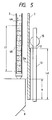
- Fig. 10 illustrates an altering characteristics of the coolant leakage flow variation depending on the axial location of the step portion 12 of the channel box 2 as a parameter. That is, Fig. 10 illustrates changing of the coolant leakage flow variation depending on the axial length H (refer to Fig. 5) of the fitting of the channel box 2 with the lower tie plate 8 at assembling of the fuel assembly (burn up 0 Gwd/t).
- Fig. 10 illustrates an altering characteristics of the coolant leakage flow variation depending on the axial location of the step portion 12 of the channel box 2 as a parameter. That is, Fig. 10 illustrates changing of the coolant leakage flow variation depending on the axial length H (refer to Fig. 5) of the fitting of the channel box 2 with the lower tie plate 8 at assembling of the fuel assembly (burn up 0 Gwd/t).
- the coolant leakage flow variation becomes nearly constant all through a fuel cycle when the axial length of the lower thick wall region 2a is at least 1.5 H.
- the coolant leakage flow variation with the axial length of the lower thick wall region 2a of 1.5 H is almost 90 % of the variation of the case when the thick wall region is extended through whole axial length of the channel box 2A. Accordingly, the axial length of the lower thick wall region 2a at least 1.5 H is preferable.
- the axial length of the lower thick wall region is almost 3 H. Generally speaking, the H is about 5-6 cm.
- Control rods for regulating the nuclear reactor power are inserted among the fuel assemblies 1 loaded in the reactor core.
- the numeral 13 is the control rod.
- the control rod 13 has a cruciform cross section having four blades which extend four directions separately from the axial center of the control rod 13.
- the roller 15 is furnished at the upper end portion of the each blade rotatably. The roller 15 rotates by contacting on the external surface of the channel box 2 when the control rod 13 moves up and down. Consequently, the control rod 13 moves up and down smoothly.
- Fig. 5 illustrates a state of condition when the control rod 13 is inserted in to the lowest position of the insertable range.
- the step portion 12 is furnished at a position avoiding interference with the roller 15.
- the fuel assembly 1 of the present embodiment is usable with the conventional control rod 13 without any modification. Because of the channel box 2 having the thin wall middle portion of the side wall 2c between the corner portions 2b, a following effect is obtained. That is, in the cross section of the channel box 2, the external surface of the middle portion of the side wall 2c locates more inner side of the channel box 2 than the external surface of the corner portion 2b. Consequently, a gap width between the middle portion of the side wall 2c and the side wall of the control rod 13 blade is larger than a gap width between the corner portion 2b and the control rod 13 blade. Accordingly, the allowable quantity of deformation at the middle portion of the side wall 2c toward outside increases, and an interference between the channel box 2 and the control rod 13 can be avoided. Also, the channel box 2 does not have any negative effect to operation of control rod 13 inserted among the fuel assemblies 1.
- the channel box 2 relating to the present embodiment can be applied to both the fuel assembly having a 8 by 8 matrix of fuel rods and the fuel assembly having a 10 by 10 matrix of fuel rods.
- the fuel assembly 1A of the present embodiment comprises the channel box 2A having the upper thick wall region 2d in addition to the lower thick wall region 2a, thick wall corner portion 2b and thin wall middle portion of the side wall 2c.
- the fuel assembly 1A has the same structure as the previously described fuel assembly 1 except the channel box 2A.
- Detailed structure of the channel box 2A is illustrated in Fig. 12.
- the channel box 2A can be considered to have a structure in which the upper thick wall region 2d is added to the same structure as the channel box 2.
- the upper thick wall region 2d has an uniform wall thickness all through the circumference of the channel box as same as the lower thick wall region 2a.
- the wall thickness of the upper thick wall region 2d is the same as the wall thickness of the corner portion 2b.
- cross sections of both the lower thick wall region 2a and the upper thick wall region 2d have the shape illustrated in Fig. 4, and a cross section of the channel box including the middle portion of the side wall 2c has the shape illustrated in Fig. 3.
- the axial length of the upper thick wall region 2d is Lu from the upper end of the channel box 2A. At the upper end of the channel box 2a, clips 21 are furnished.
- the channel box 2A is fixed to the upper tie plate 7 at the upper end in a condition in which the triangle shape clips 21 are respectively fixed at two diagonal corners of the upper end as illustrated in Fig. 13. That means, the clip 21 contacts with surface of the post 22 (Fig. 11) furnished at corners of the upper tie plate 7 by covering of the channel ox 2A.
- the channel fastener 10 is arranged at the corner located with one of the clips 21, and is fixed to one of the posts 22 with the screw 10A.
- the clip 21 between the channel fastener 10 and the post 22 is fixed to the post 22 of the upper tie plate 7 with the screw 10A. Fixing of the channel box and the channel fastener in the above described manner is applied to the previously described fuel assembly 1 as well.
- the channel spacer 20 is fixed at the upper thick wall region 2d (Fig. 12).
- the fuel assembly 1A is supported by insertion of its lower tie plate 8 into the fuel supporting metal fitting 9 as illustrated in Fig. 14.
- the upper end of the fuel assembly 1A is inserted into a grid of the upper grid plate 23 of the reactor core.
- One fuel supporting metal fitting 9 supports each lower tie plates 8 of the adjacent four fuel assemblies 1A surrounding the control rod 13.
- Each of the upper ends of the four fuel assemblies 1A is inserted into one of grids of the upper grid plate 23 of the reactor core.
- Each of the channel fasteners 10 of the four fuel assemblies 1A contacts each other, and horizontally presses the upper end portion of each fuel assemblies 1A, that is, the upper thick wall region 2d of the channel box 2A, toward the upper grid plate 23 of the reactor core. That means, the upper thick wall region 2d contacts with the upper grid plate 23 of the reactor core.
- the channel spacer 20 illustrated in Fig. 12 acts as a back up for an occasion of the channel fastener 10 failure.
- the fuel assembly 1A has the same effect as the previously described fuel assembly 1 obtains.
- the fuel assembly 1A is able to solve the problems existing in the fuel assembly 1 by having the upper thick wall region 2d.
- Each of fuel assemblies 1 in a condition being loaded in the reactor core presses each other with each channel fasteners 10 as previously described.
- a reaction force is added in an earthquake to planes contacting with the upper grid plate 23 in the reactor core and the fixing portion of the channel spacer 20 at the upper end portion of the channel box 2.
- two fuel assemblies out of the four fuel assemblies 1 being arranged in the grids of the upper grid plate 23 in the reactor core move toward the other two fuel assemblies. Consequently, the elastic channel fasteners 10 of the each fuel assemblies are compressed, and the each channel spacers 20 collides each other.
- the fuel assembly 1A is able to moderate the previously described generation of the stress concentration at the fuel assembly 1.
- the upper thick wall region 2d is furnished at the upper end portion of the channel box 2A which contacts with the upper grid plate 23 in the reactor core, and accordingly, the reaction force added to the fuel channel box 2A in an earthquake can be born by the whole side wall of the upper thick wall region 2d.
- Fig. 15 is a schematic illustration of an axial fitting of a vertical cross section of one side of the channel box 2A with the control rod 13.
- the channel box 2A forms a guide plane for both inserting and withdrawing operations of the control rod 13 among the fuel assemblies 1A.
- the channel box 2A is allowed to have the deflection C in manufacturing process.
- the axial length Lu of the upper thick wall region 2d which is necessary for not protruding the step portion 24 at the upper thick wall region 2d toward the control rod side beyond the middle portion of the channel box 2A can be calculated by the following equation.
- L is the axial full length of the channel box 2A.
- the channel box having four meters of L is generally used for the fuel assembly.
- the L of the channel box 2A is about four meters.
- C becomes about 4 millimeters.
- the step difference B on exterior surface of the channel box 2A at the corner portion 2b and the flat middle portion 2c of the side wall is generally about 1 millimeter.
- the preferable axial length Lu of the upper thick wall region 2d of the channel box 2A is within a range of 25 % of the full length L of the channel box 2A.
- the Lu is within 25 % of the L, both inserting and withdrawing operations of the control rod 13 among the fuel assemblies 1A are not influenced with any undesirable effect.
- the above Lu does not decrease substantial function of uneven surface of the channel box 2A.
- the upper thick wall region 2d is preferably arranged toward the upper end portion of the channel box 2A as possible in view of other requirement.
- Fig. 14 illustrates a state when the control rod 13 is fully inserted among the fuel assemblies 1A.
- External surface of the channel box 2A forms a guide plane for up and down moving of the control rod 13, and accordingly, location of the upper thick wall region 2d is preferably determined not to interfere with the roller 15 when the control rod 13 is fully inserted. That means, the axial length Lu of the upper thick wall region 2d must be within the distance D from the upper end of the channel box 2A to the roller 15 when the control rod 13 is fully inserted. Consequently, the axial length Lu of the upper thick wall region 2d is preferably within 15 % of the full length L of the channel box 2A.
- the wall thickness of the channel box 2A is preferably made as thin as possible. Accordingly, the region of the channel box 2A except the lower thick wall region 2a and the upper thick wall region 2d has a thinner wall thickness at the middle portion of the side wall 2c than the wall thickness at the corner portion 2b in order to prevent the cross sectional area from being increased.
- the upper thick wall region 2d preferably locates upward from the upper end of the effective fuel length portion of the fuel rod 3 illustrated in Fig. 11.
- the length Lu of the upper thick wall region 2d of the channel box 2A within 10 % of the full length L of the channel box 2A is preferable in order not to overlap with the effective fuel length portion.
- the channel box 2B of the present embodiment is manufactured by welding two long members 25 and 26 having U shape cross section respectively to combine together for forming a long rectangular pipe.
- Wall thicknesses in the vicinity of the welding portion 27 at the middle portion of the side wall of both the lower thick wall region 2a and the upper thick wall region 2d are the same as the thin wall thickness at the middle portion of the side wall 2c. Accordingly, the wall thickness near the welding portion 27 becomes uniform all though the axial length, and determination of welding condition etc. is facilitated.
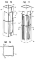
- the channel box 2D has a structure being formed the vertical grooves 28 at the thin middle portion of the side wall 2c.
- the vertical grooves 28 are totally formed eight, two on each sides of the channel box 2D, at the middle portion of the side walls as illustrated in Figs. 17 and 18.
- the vertical grooves 28 are formed by eliminating the material from areas where bending moment and stress on the channel box 2D become minimum.
- the wall thickness at the portion where the vertical groove 28 is formed is thinner than the wall thickness at the middle portion 2c of the side wall.
- the channel box 2D is reduced in the quantity of the material by having a thinner wall thickness than the wall thicknesses of the channel boxes 2, 2A, and 2B, in the other embodiments, and accordingly, both the neutron economy and the fuel economy are further improved.
- one of the eight grooves 28 is preferably furnished along the path where the roller 15 of the control rod 13 moves up and down. The reason is not to restrict the up and down movement of the control rod roller 15 by an adjacent channel box when the channel box deforms outward.
Landscapes
- Physics & Mathematics (AREA)
- Engineering & Computer Science (AREA)
- Plasma & Fusion (AREA)
- General Engineering & Computer Science (AREA)
- High Energy & Nuclear Physics (AREA)
- Monitoring And Testing Of Nuclear Reactors (AREA)
Claims (11)
- Brennstoffkassette, mit
einer oberen Ankerplatte (7),
einer unteren Ankerplatte (8),
mehreren Brennstoffstäben, wobei das obere Ende und das untere Ende jedes Brennstoffstabes durch die obere Ankerplatte (7) bzw. durch die untere Ankerplatte (8) unterstützt ist und wobei die Brennstoffstäbe jeweils in einem unteren Endabschnitt einen Bereich für natürliches Uran (4B), der natürliches Uran enthält, und oberhalb des Bereichs (4B) für natürliches Uran einen Bereich (4A) enthalten, der angereichertes Spaltmaterial enthält, und
einem Kanalkasten (2, 2A), der an der oberen Ankerplatte (7) befestigt ist und ein Bündel der Brennstoffstäbe (3) sowie die untere Ankerplatte (8) umgibt,
wobei eine Wanddicke in einem unteren dickwandigen Bereich (2a) des Kanalkastens (2, 2A) dicker als eine Wanddicke in einem oberhalb des unteren dickwandigen Bereichs (2a) befindlichen Bereich (2c) und zwischen den Eckabschnitten (2b) des Kanalkastens (2, 2A) ist,
dadurch gekennzeichnet, daß
sich das obere Ende (12) des unteren dickwandigen Bereichs (2a) oberhalb der Oberseite der unteren Ankerplatte (8) und unterhalb des oberen Endes des Bereichs (4B) für natürliches Uran befindet. - Brennstoffkassette nach Anspruch 1, bei der sich das obere Ende des unteren dickwandigen Bereichs (2a) an einer Position befindet, die von einem unteren Ende der unteren Ankerplatte (8) um eine Strecke entfernt ist, die wenigstens gleich der 1,5fachen axialen Länge zwischen der Oberseite der unteren Ankerplatte (8) und einem unteren Ende des Kanalkastens (2, 2A) im montierten Zustand ist.
- Brennstoffkassette nach Anspruch 1, bei der eine Wanddicke im Eckabschnitt (2b) des Kanalkastens (2, 2A) dicker als eine Wanddicke im Mittelabschnitt (2c) der Seitenwand ist, die sich zwischen den Eckabschnitten (2b) in einem Bereich oberhalb des unteren dickwandigen Bereichs (2a) des Kanalkastens (2, 2A) befindet.
- Brennstoffkassette nach Anspruch 3, bei der die Wanddicke im unteren dickwandigen Bereich (2a) gleich der Wanddicke in den Eckabschnitten (2b) ist.
- Brennstoffkassette nach Anspruch 1, bei der die Wanddicke in einem oberen dickwandigen Bereich (2d), der am oberen Ende des Kanalkastens (2, 2A) ausgebildet ist, dicker ist als die Wanddicke in dem Bereich (2c), der sich zwischen dem oberen dickwandigen Bereich (2d) und dem unteren dickwandigen Bereich (2a) befindet, und dikker als die Wanddicke zwischen den Eckabschnitten (2b).
- Brennstoffkassette nach Anspruch 5, bei der die Wanddicken im unteren dickwandigen Bereich (2a) und im oberen dickwandigen Bereich (2d) über den gesamten Querschnitt der Bereiche hinweg gleichmäßig sind.
- Brennstoffkassette nach Anspruch 5, bei der sich das obere Ende des unteren dickwandigen Bereichs (2a) an einer Position befindet, die von einem unteren Ende der unteren Ankerplatte (8) um eine Strecke entfernt ist, die wenigstens gleich der 1,5fachen axialen Länge zwischen der Oberseite der unteren Ankerplatte (8) und einem unteren Ende des Kanalkastens im montierten Zustand ist.
- Brennstoffkassette nach Anspruch 5, bei der eine Wanddicke im Eckabschnitt (2b) dicker als eine Wanddicke im Mittelabschnitt (2c) der Seitenwand ist, die sich zwischen den Eckabschnitten (2b) des Kanalkastens (2, 2A) in einem Bereich zwischen dem unteren dickwandigen Bereich (2a) und dem oberen dickwandigen Bereich (2d) des Kanalkastens (2, 2A) befindet.
- Brennstoffkassette nach Anspruch 8, bei der die Wanddicken im unteren dickwandigen Bereich (2a) und im oberen dickwandigen Bereich (2d) gleich der Wanddicke an den Eckabschnitten sind.
- Brennstoffkassette nach Anspruch 5, bei der im oberen dickwandigen Bereich (2d) Kanal-Abstandshalter (20) vorgesehen sind.
- Brennstoffkassette nach Anspruch 5, bei der eine axiale Länge des oberen dickwandigen Bereichs (2d) wenigstens 25 % der axialen Gesamtlänge des Kanalkastens (2, 2A) beträgt.
Applications Claiming Priority (4)
| Application Number | Priority Date | Filing Date | Title |
|---|---|---|---|
| JP29789/91 | 1991-02-25 | ||
| JP3029789A JP3070771B2 (ja) | 1991-02-25 | 1991-02-25 | 燃料集合体 |
| JP03143409A JP3088487B2 (ja) | 1991-06-14 | 1991-06-14 | 燃料集合体及び燃料チャンネルボックス |
| JP143409/91 | 1991-06-14 |
Publications (2)
| Publication Number | Publication Date |
|---|---|
| EP0501259A1 EP0501259A1 (de) | 1992-09-02 |
| EP0501259B1 true EP0501259B1 (de) | 1995-08-02 |
Family
ID=26368023
Family Applications (1)
| Application Number | Title | Priority Date | Filing Date |
|---|---|---|---|
| EP92102529A Revoked EP0501259B1 (de) | 1991-02-25 | 1992-02-14 | Brennstoffbündel mit Strömungskanal |
Country Status (3)
| Country | Link |
|---|---|
| US (1) | US5265139A (de) |
| EP (1) | EP0501259B1 (de) |
| DE (1) | DE69203750T2 (de) |
Families Citing this family (10)
| Publication number | Priority date | Publication date | Assignee | Title |
|---|---|---|---|---|
| US5574761A (en) * | 1995-09-29 | 1996-11-12 | Crs Holdings, Inc. | Fuel channels with off-centerline welds |
| US7702060B2 (en) * | 2006-10-20 | 2010-04-20 | Global Nuclear Fuel - Americas, L.L.C. | Expanded nuclear fuel channel |
| US8116423B2 (en) | 2007-12-26 | 2012-02-14 | Thorium Power, Inc. | Nuclear reactor (alternatives), fuel assembly of seed-blanket subassemblies for nuclear reactor (alternatives), and fuel element for fuel assembly |
| JP5585883B2 (ja) | 2007-12-26 | 2014-09-10 | トリウム・パワー、インク | 核燃料集合体、核燃料集合体を含む軽水炉、及び核燃料集合体の使用方法 |
| CA2748367C (en) | 2008-12-25 | 2016-11-29 | Thorium Power, Inc. | A light-water reactor fuel assembly and a fuel element thereof |
| WO2011143172A1 (en) | 2010-05-11 | 2011-11-17 | Thorium Power, Inc. | Fuel assembly with metal fuel alloy kernel and method of manufacturing thereof |
| US10170207B2 (en) | 2013-05-10 | 2019-01-01 | Thorium Power, Inc. | Fuel assembly |
| US10192644B2 (en) | 2010-05-11 | 2019-01-29 | Lightbridge Corporation | Fuel assembly |
| US9287012B2 (en) | 2010-07-25 | 2016-03-15 | Global Nuclear Fuel—Americas, LLC | Optimized fuel assembly channels and methods of creating the same |
| WO2016146149A1 (en) * | 2015-03-13 | 2016-09-22 | Westinghouse Electric Sweden Ab | Fuel channel for a nuclear boiling water reactor |
Family Cites Families (5)
| Publication number | Priority date | Publication date | Assignee | Title |
|---|---|---|---|---|
| US4749544A (en) * | 1987-03-24 | 1988-06-07 | General Electric Company | Thin walled channel |
| US4749543A (en) * | 1987-03-24 | 1988-06-07 | General Electric Company | Axially shaped channel and integral flow trippers |
| DE3834611C3 (de) * | 1987-10-13 | 1998-02-12 | Toshiba Kawasaki Kk | Brennstoffanordnung für einen Kernreaktor |
| US5009840A (en) * | 1988-01-23 | 1991-04-23 | Kabushiki Kaisha Toshiba | Fuel assembly for nuclear reactor |
| US4889684A (en) * | 1988-08-01 | 1989-12-26 | General Electric Company | Hydraulic reinforcement of channel at lower tie-plate in BWR fuel bundle |
-
1992
- 1992-02-14 DE DE69203750T patent/DE69203750T2/de not_active Revoked
- 1992-02-14 EP EP92102529A patent/EP0501259B1/de not_active Revoked
- 1992-02-25 US US07/840,939 patent/US5265139A/en not_active Expired - Lifetime
Also Published As
| Publication number | Publication date |
|---|---|
| EP0501259A1 (de) | 1992-09-02 |
| DE69203750T2 (de) | 1996-01-18 |
| US5265139A (en) | 1993-11-23 |
| DE69203750D1 (de) | 1995-09-07 |
Similar Documents
| Publication | Publication Date | Title |
|---|---|---|
| US4749544A (en) | Thin walled channel | |
| US5202085A (en) | Fuel assembly and reactor core | |
| EP2267726B1 (de) | Leichtwasserreaktorkern und Brennstabbündel | |
| EP0204288B1 (de) | Brennstabbündel | |
| US5544211A (en) | Nuclear fuel assembly and nuclear reactor incorporating the same | |
| EP0501259B1 (de) | Brennstoffbündel mit Strömungskanal | |
| EP2088600A1 (de) | Kern eines Siedewasserreaktors | |
| US20090196392A1 (en) | Core Of A Boiling Water Reactor | |
| US5422922A (en) | Fuel assembly and reactor core | |
| EP0284016A2 (de) | Brennstoffanordnung | |
| USRE34246E (en) | Thin walled channel | |
| JPS60201284A (ja) | 燃料集合体 | |
| JP2597589B2 (ja) | 燃料集合体 | |
| US5319685A (en) | Method for operation of a boiling water nuclear reactor | |
| JP2610254B2 (ja) | 沸騰水型原子炉 | |
| JP2510196B2 (ja) | 燃料集合体 | |
| JPH11109073A (ja) | 沸騰水型原子炉用燃料集合体 | |
| JP2002328192A (ja) | 燃料集合体 | |
| JP3009183B2 (ja) | 原子炉の炉心 | |
| JPS5826292A (ja) | 燃料集合体 | |
| JP2625404B2 (ja) | 燃料集合体 | |
| JP3314382B2 (ja) | 燃料集合体 | |
| JPS6276490A (ja) | 原子炉用制御棒 | |
| JP3788170B2 (ja) | 燃料集合体及び原子炉炉心 | |
| JPH0452912B2 (de) |
Legal Events
| Date | Code | Title | Description |
|---|---|---|---|
| PUAI | Public reference made under article 153(3) epc to a published international application that has entered the european phase |
Free format text: ORIGINAL CODE: 0009012 |
|
| 17P | Request for examination filed |
Effective date: 19920601 |
|
| AK | Designated contracting states |
Kind code of ref document: A1 Designated state(s): DE FR GB |
|
| 17Q | First examination report despatched |
Effective date: 19940323 |
|
| GRAA | (expected) grant |
Free format text: ORIGINAL CODE: 0009210 |
|
| AK | Designated contracting states |
Kind code of ref document: B1 Designated state(s): DE FR GB |
|
| REF | Corresponds to: |
Ref document number: 69203750 Country of ref document: DE Date of ref document: 19950907 |
|
| ET | Fr: translation filed | ||
| PLBI | Opposition filed |
Free format text: ORIGINAL CODE: 0009260 |
|
| 26 | Opposition filed |
Opponent name: SIEMENS AG Effective date: 19960410 |
|
| PLBF | Reply of patent proprietor to notice(s) of opposition |
Free format text: ORIGINAL CODE: EPIDOS OBSO |
|
| PLBF | Reply of patent proprietor to notice(s) of opposition |
Free format text: ORIGINAL CODE: EPIDOS OBSO |
|
| PLBO | Opposition rejected |
Free format text: ORIGINAL CODE: EPIDOS REJO |
|
| APAC | Appeal dossier modified |
Free format text: ORIGINAL CODE: EPIDOS NOAPO |
|
| APAE | Appeal reference modified |
Free format text: ORIGINAL CODE: EPIDOS REFNO |
|
| APAC | Appeal dossier modified |
Free format text: ORIGINAL CODE: EPIDOS NOAPO |
|
| PGFP | Annual fee paid to national office [announced via postgrant information from national office to epo] |
Ref country code: FR Payment date: 20010123 Year of fee payment: 10 |
|
| PGFP | Annual fee paid to national office [announced via postgrant information from national office to epo] |
Ref country code: DE Payment date: 20010330 Year of fee payment: 10 |
|
| PLBQ | Unpublished change to opponent data |
Free format text: ORIGINAL CODE: EPIDOS OPPO |
|
| PLAB | Opposition data, opponent's data or that of the opponent's representative modified |
Free format text: ORIGINAL CODE: 0009299OPPO |
|
| REG | Reference to a national code |
Ref country code: GB Ref legal event code: IF02 |
|
| R26 | Opposition filed (corrected) |
Opponent name: FRAMATOME ANP GMBH Effective date: 19960410 |
|
| PGFP | Annual fee paid to national office [announced via postgrant information from national office to epo] |
Ref country code: GB Payment date: 20020129 Year of fee payment: 11 |
|
| APAC | Appeal dossier modified |
Free format text: ORIGINAL CODE: EPIDOS NOAPO |
|
| RDAH | Patent revoked |
Free format text: ORIGINAL CODE: EPIDOS REVO |
|
| RDAG | Patent revoked |
Free format text: ORIGINAL CODE: 0009271 |
|
| STAA | Information on the status of an ep patent application or granted ep patent |
Free format text: STATUS: PATENT REVOKED |
|
| 27W | Patent revoked |
Effective date: 20020214 |
|
| GBPR | Gb: patent revoked under art. 102 of the ep convention designating the uk as contracting state |
Free format text: 20020214 |
|
| APAH | Appeal reference modified |
Free format text: ORIGINAL CODE: EPIDOSCREFNO |