EP0501444A2 - Radiateur - Google Patents
Radiateur Download PDFInfo
- Publication number
- EP0501444A2 EP0501444A2 EP92103259A EP92103259A EP0501444A2 EP 0501444 A2 EP0501444 A2 EP 0501444A2 EP 92103259 A EP92103259 A EP 92103259A EP 92103259 A EP92103259 A EP 92103259A EP 0501444 A2 EP0501444 A2 EP 0501444A2
- Authority
- EP
- European Patent Office
- Prior art keywords
- separating
- collecting line
- manifold
- heat
- plugs
- Prior art date
- Legal status (The legal status is an assumption and is not a legal conclusion. Google has not performed a legal analysis and makes no representation as to the accuracy of the status listed.)
- Granted
Links
- 238000006073 displacement reaction Methods 0.000 claims abstract description 10
- 239000004033 plastic Substances 0.000 claims abstract description 6
- 238000007373 indentation Methods 0.000 claims description 9
- 239000012530 fluid Substances 0.000 claims description 3
- 230000000149 penetrating effect Effects 0.000 claims description 2
- 238000010438 heat treatment Methods 0.000 description 4
- 229910000831 Steel Inorganic materials 0.000 description 1
- 230000032683 aging Effects 0.000 description 1
- 238000005553 drilling Methods 0.000 description 1
- 230000000694 effects Effects 0.000 description 1
- 230000037431 insertion Effects 0.000 description 1
- 238000003780 insertion Methods 0.000 description 1
- 239000002184 metal Substances 0.000 description 1
- 238000007789 sealing Methods 0.000 description 1
- 229910001220 stainless steel Inorganic materials 0.000 description 1
- 239000010935 stainless steel Substances 0.000 description 1
- 239000010959 steel Substances 0.000 description 1
Images


Classifications
-
- F—MECHANICAL ENGINEERING; LIGHTING; HEATING; WEAPONS; BLASTING
- F28—HEAT EXCHANGE IN GENERAL
- F28F—DETAILS OF HEAT-EXCHANGE AND HEAT-TRANSFER APPARATUS, OF GENERAL APPLICATION
- F28F9/00—Casings; Header boxes; Auxiliary supports for elements; Auxiliary members within casings
- F28F9/02—Header boxes; End plates
- F28F9/0202—Header boxes having their inner space divided by partitions
- F28F9/0204—Header boxes having their inner space divided by partitions for elongated header box, e.g. with transversal and longitudinal partitions
- F28F9/0209—Header boxes having their inner space divided by partitions for elongated header box, e.g. with transversal and longitudinal partitions having only transversal partitions
- F28F9/0212—Header boxes having their inner space divided by partitions for elongated header box, e.g. with transversal and longitudinal partitions having only transversal partitions the partitions being separate elements attached to header boxes
Definitions
- the invention relates to a heat body, preferably a radiant ceiling panel, consisting of a plurality of adjacent heat exchange elements connected in parallel on the fluid side and / or one behind the other, the inflow and outflow of which are connected to a continuous collecting line, in which, for dividing the collecting line into individual line sections, elastic separating plugs, preferably made of rubber or plastic.
- Such heat bodies are known in particular as radiant ceiling panels. They are composed of several heat exchange elements of the same type, which are connected on the inflow and outflow sides to a continuous collecting line.
- separating plugs are arranged, on the one hand to avoid a short circuit between the inflow and outflow of the heating medium flowing through the heating element when the inflow and outflow are connected to the same collecting line, and on the other hand to divide the collecting lines into individual line sections when the heat exchange elements forming the heating element form several exchange surfaces lying next to one another but through which flow flows in the opposite direction.
- the separating plugs which are preferably made of rubber or plastic, are produced with outer dimensions that are slightly larger than the inner dimensions of the collecting pipe into which the separating plugs are inserted.
- the separating plugs are non-positively fixed in the manifolds. Since the elasticity of the separating plugs wears off over time, especially since the separating plugs are also exposed to an aggressive heat medium, it cannot be ruled out that, particularly at high flow velocities, displacements of the separating plugs occur within the collecting lines. Such displacements change the distribution of the heat medium within the heat exchange elements, which can be associated with a considerable reduction in the heat output. In addition, such shifts are not recognizable from the outside without destroying the manifolds.
- the invention has for its object to develop heat bodies of the type defined in such a way that undesirable displacements of the separating plugs are prevented.
- the solution to this problem by the invention is characterized in that the separating plugs are positively fixed against displacement in the manifold by stop surfaces formed in the interior of the manifold. This prevents undesired displacements of the separating plugs that are not visible from the outside.
- the stop surfaces can be formed by indentations in the wall of the collecting line. These indentations are applied after the separating plugs have been placed in the respective position within the manifold. The type of indentation depends on the cross-section of the manifold.
- the stop surfaces can be formed by a pin which is inserted into a bore penetrating at least one wall of the collecting line and at least part of the separating plug.
- This pin is inventively at least at one end with the Welded manifold.
- the inside diameter of the bore in the separating plug can be made slightly smaller than the outside diameter of the pin, so that by inserting the pin into the separating plug an expansion of the separating plug results, which leads to a closer contact of the separating plug with the wall of the Bus line leads.
- FIG. 1 shows a total of 12 examples of radiant panels designed as radiant ceiling panels, each of which is made from two or more identical heat exchange elements 1.
- All heat exchange elements 1 of a heat body are connected at their two ends to common manifolds 2, which consequently run over the entire respective width of the heat body.
- stop surfaces are formed in the interior of the respective collecting line 2, which fix the respective separating plug 3 in a form-fitting manner against displacement in the collecting line 2.
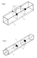
- FIG. 2 shows a perspective view of a first exemplary embodiment of a collecting line 2 with a rectangular cross section based on a partial length of this collecting line 2.
- the separating plug 3 inserted into this manifold 2 can be seen in broken lines. It is held in the respectively predetermined position by indentations 4, which are formed in the exemplary embodiment according to FIG. 2 in two adjacent corners of the collecting line 2 after the separating plug 3 has reached its predetermined one Position in the manifold 2 has been brought.
- These indentations 4 form stop surfaces for the separating plug 3 in the interior of the collecting line 2, so that the latter cannot shift even at higher flow velocities and higher pressures and despite aging of the separating plug 3 which occurs over time.
- FIG. 3 shows a manifold 2 which is circular in cross section and in which a correspondingly cylindrical separating plug 3 is arranged. This separating plug 3 is also positively fixed in its predetermined position by indentations 4.
- the third exemplary embodiment according to FIG. 4 shows the section of a collecting pipe 2 with a triangular cross section, into which a corresponding triangular separating plug 3 is inserted.
- the separating plug 3 is positively fixed by a single indentation 4 which is formed in one of the three surfaces of the collecting line 2 as soon as the separating plug 3 has assumed the predetermined position in the collecting line 2.
- FIG. 5 shows an alternative embodiment of the stop surfaces for the form-fitting fixing of the separating plugs 3 in a perspective illustration corresponding to FIG. 2 of a section of a collecting line 2 with a rectangular cross section.
- the separating plug 3 shown in broken lines is fixed by a pin 5 which is secured by a hole is inserted in one of the four walls of the collecting line 2 and protrudes into a hole 3a in the separating plug 3.
- the pin 5 is welded to the manifold 2, as indicated in Fig. 5.
- This pin 5 also forms stop surfaces within the manifold 2, which form-fit the separating plug 3 at its predetermined position hold the manifold 2. If the inside diameter of the bore 3a is made slightly smaller than the outside diameter of the pin 5, the insertion of the pin 5 into the separating plug 3 also results in an expansion of the separating plug 3, which increases the sealing effect.
- the heat bodies can be formed from any number of heat exchange elements 1, the cross section of the manifolds 2 used here also being arbitrary.
- the heat exchange elements 1 and manifolds 2 can consist of metal, preferably steel or stainless steel, but also of suitable plastic.
- the elastic separating plugs 3 are preferably made of rubber or plastic.
Landscapes
- Engineering & Computer Science (AREA)
- Physics & Mathematics (AREA)
- Thermal Sciences (AREA)
- Mechanical Engineering (AREA)
- General Engineering & Computer Science (AREA)
- Steam Or Hot-Water Central Heating Systems (AREA)
- Surgical Instruments (AREA)
- Cooling Or The Like Of Electrical Apparatus (AREA)
- Heat-Exchange Devices With Radiators And Conduit Assemblies (AREA)
- Resistance Heating (AREA)
- Yarns And Mechanical Finishing Of Yarns Or Ropes (AREA)
- Air-Conditioning For Vehicles (AREA)
Applications Claiming Priority (2)
| Application Number | Priority Date | Filing Date | Title |
|---|---|---|---|
| DE9102265U DE9102265U1 (de) | 1991-02-26 | 1991-02-26 | Wärmekörper |
| DE9102265U | 1991-02-26 |
Publications (3)
| Publication Number | Publication Date |
|---|---|
| EP0501444A2 true EP0501444A2 (fr) | 1992-09-02 |
| EP0501444A3 EP0501444A3 (fr) | 1992-12-30 |
| EP0501444B1 EP0501444B1 (fr) | 1995-11-22 |
Family
ID=6864669
Family Applications (1)
| Application Number | Title | Priority Date | Filing Date |
|---|---|---|---|
| EP92103259A Expired - Lifetime EP0501444B1 (fr) | 1991-02-26 | 1992-02-26 | Radiateur |
Country Status (4)
| Country | Link |
|---|---|
| EP (1) | EP0501444B1 (fr) |
| AT (1) | ATE130672T1 (fr) |
| DE (2) | DE9102265U1 (fr) |
| DK (1) | DK0501444T3 (fr) |
Cited By (4)
| Publication number | Priority date | Publication date | Assignee | Title |
|---|---|---|---|---|
| GB2271630A (en) * | 1992-10-17 | 1994-04-20 | Howard Ind Pipework Services L | Panel adapted for coolant through-flow and an article incorporating such panels |
| EP0709644A3 (fr) * | 1994-10-26 | 1996-05-08 | Valeo Engine Cooling Inc | |
| FR2735856A1 (fr) * | 1995-06-23 | 1996-12-27 | Valeo Thermique Moteur Sa | Procede de fixation de cloisons transversales dans une boite a fluide tubulaire d'echangeur de chaleur |
| FR2745078A1 (fr) * | 1996-02-20 | 1997-08-22 | Valeo Thermique Moteur Sa | Procede de sertissage de cloisons transversales dans une boite a fluide |
Families Citing this family (5)
| Publication number | Priority date | Publication date | Assignee | Title |
|---|---|---|---|---|
| DE9102265U1 (de) * | 1991-02-26 | 1991-05-16 | Zehnder-Beutler GmbH, 7630 Lahr | Wärmekörper |
| EP0851188B8 (fr) * | 1996-12-25 | 2006-01-11 | Calsonic Kansei Corporation | Structure d'assemblage d'un condenseur |
| EP1102016B1 (fr) | 1999-11-17 | 2003-03-12 | Zehnder Verkaufs- und Verwaltungs AG | Radiateur |
| DE20102851U1 (de) | 2001-02-16 | 2001-06-07 | Menge, Klaus, 64823 Groß-Umstadt | Strahlflächenaufbau |
| DE102019000575B4 (de) * | 2019-01-26 | 2024-02-01 | Diehl Aerospace Gmbh | Ausheben von Leiterkarten |
Family Cites Families (7)
| Publication number | Priority date | Publication date | Assignee | Title |
|---|---|---|---|---|
| FR1256482A (fr) * | 1960-05-09 | 1961-03-17 | Licencia Talalmanyokat | Chambre de distribution d'eau pour échangeurs de chaleur et cloison de séparation la constituant |
| FR2271531B2 (fr) * | 1973-12-13 | 1976-10-08 | Chausson Usines Sa | |
| GB2082312A (en) * | 1980-08-21 | 1982-03-03 | Imi Radiators | Header tank construction |
| DE3752324T2 (de) * | 1986-07-29 | 2001-03-29 | Showa Aluminium Co Ltd | Kondensator |
| US4936381A (en) * | 1988-12-27 | 1990-06-26 | Modine Manufacturing Company | Baffle for tubular header |
| US4960169A (en) * | 1989-06-20 | 1990-10-02 | Modien Manufacturing Co. | Baffle for tubular heat exchanger header |
| DE9102265U1 (de) * | 1991-02-26 | 1991-05-16 | Zehnder-Beutler GmbH, 7630 Lahr | Wärmekörper |
-
1991
- 1991-02-26 DE DE9102265U patent/DE9102265U1/de not_active Expired - Lifetime
-
1992
- 1992-02-26 EP EP92103259A patent/EP0501444B1/fr not_active Expired - Lifetime
- 1992-02-26 DK DK92103259.5T patent/DK0501444T3/da active
- 1992-02-26 DE DE59204383T patent/DE59204383D1/de not_active Expired - Fee Related
- 1992-02-26 AT AT92103259T patent/ATE130672T1/de not_active IP Right Cessation
Cited By (7)
| Publication number | Priority date | Publication date | Assignee | Title |
|---|---|---|---|---|
| GB2271630A (en) * | 1992-10-17 | 1994-04-20 | Howard Ind Pipework Services L | Panel adapted for coolant through-flow and an article incorporating such panels |
| GB2271630B (en) * | 1992-10-17 | 1996-06-12 | Howard Ind Pipework Services L | Panel adapted for coolant through-flow and an article incorporating such panels |
| EP0709644A3 (fr) * | 1994-10-26 | 1996-05-08 | Valeo Engine Cooling Inc | |
| FR2735856A1 (fr) * | 1995-06-23 | 1996-12-27 | Valeo Thermique Moteur Sa | Procede de fixation de cloisons transversales dans une boite a fluide tubulaire d'echangeur de chaleur |
| WO1997001073A1 (fr) * | 1995-06-23 | 1997-01-09 | Valeo Thermique Moteur | Procede de fixation de cloisons transversales dans une boite a fluide tubulaire d'echangeur de chaleur |
| US6308410B1 (en) | 1995-06-23 | 2001-10-30 | Valeo Thermique Moteur | Method for fixing transverse partitions in the tubular fluid box of a heat exchanger |
| FR2745078A1 (fr) * | 1996-02-20 | 1997-08-22 | Valeo Thermique Moteur Sa | Procede de sertissage de cloisons transversales dans une boite a fluide |
Also Published As
| Publication number | Publication date |
|---|---|
| DK0501444T3 (da) | 1996-04-09 |
| EP0501444B1 (fr) | 1995-11-22 |
| EP0501444A3 (fr) | 1992-12-30 |
| DE59204383D1 (de) | 1996-01-04 |
| DE9102265U1 (de) | 1991-05-16 |
| ATE130672T1 (de) | 1995-12-15 |
Similar Documents
| Publication | Publication Date | Title |
|---|---|---|
| DE69614402T2 (de) | Plattenwärmetauscher | |
| EP0655275B1 (fr) | Dispositif de mélange statique | |
| DE1944932A1 (de) | Brennstoffelement-Halterung fuer Kernreaktoren | |
| EP0501444B1 (fr) | Radiateur | |
| DE3122947A1 (de) | Waermetauscher | |
| DE4441503C2 (de) | Wärmetauscher, insbesondere für Kraftfahrzeuge | |
| DE2952736A1 (de) | Waermetauscher, insbesondere zwei-oder mehrflutiger kondensator fuer klimaanlagen in kraftfahrzeugen | |
| DE3032048A1 (de) | Distanzgitter zum stuetzen eines buendels paralleler, stabfoermiger koerper | |
| EP0447942B1 (fr) | Réglette enfichable pour une interconnexion imperméable à des rayonnements perturbateurs d'éléments de bord voisins métalliques | |
| EP3659222B1 (fr) | Agencement avec deux châssis d'armoire connectés par un dispositif d'assemblage | |
| EP0109032A2 (fr) | Installation de chauffage à distance avec un dispositif de raccordement | |
| AT230972B (de) | Führungsschienen mit Führungsnut zur Halterung und Führung von Einschubplatten | |
| DE3139796A1 (de) | Ziehstein | |
| DE2755723A1 (de) | Vorrichtung zum zurueckhalten von stoergliedern innerhalb von waermeaustauscherrohren | |
| DE102005048838A1 (de) | Wärmetauscher | |
| DE4028437A1 (de) | Waermetauscher | |
| DE3136866C2 (de) | Röhrenwärmetauscher mit Strömungsleiteinbauten | |
| DE102008002320A1 (de) | Kreuzverbinder für Streben | |
| DE2101432B2 (de) | Wärmeaustauscher mit Rohren | |
| DE102017217313A1 (de) | Wärmeübertrager | |
| DE452780C (de) | Schutzvorrichtung gegen Korrosion an Kondensatorrohren | |
| DE3628183C2 (de) | Wärmeaustauscher für den Untertagebetrieb, insbesondere Wetterkühler | |
| DE1609611C3 (de) | Gitterrost | |
| DE19718064A1 (de) | Turbulenzeinlage | |
| AT263141B (de) | Leuchtröhrenhalter |
Legal Events
| Date | Code | Title | Description |
|---|---|---|---|
| PUAI | Public reference made under article 153(3) epc to a published international application that has entered the european phase |
Free format text: ORIGINAL CODE: 0009012 |
|
| AK | Designated contracting states |
Kind code of ref document: A2 Designated state(s): AT BE CH DE DK ES FR GB GR IT LI LU MC NL PT SE |
|
| PUAL | Search report despatched |
Free format text: ORIGINAL CODE: 0009013 |
|
| RBV | Designated contracting states (corrected) |
Designated state(s): AT BE CH DE DK ES FR GB GR IT LI LU NL PT |
|
| AK | Designated contracting states |
Kind code of ref document: A3 Designated state(s): AT BE CH DE DK ES FR GB GR IT LI LU MC NL PT SE |
|
| 17P | Request for examination filed |
Effective date: 19930702 |
|
| 17Q | First examination report despatched |
Effective date: 19950109 |
|
| GRAA | (expected) grant |
Free format text: ORIGINAL CODE: 0009210 |
|
| AK | Designated contracting states |
Kind code of ref document: B1 Designated state(s): AT BE CH DE DK ES FR GB GR IT LI LU NL PT |
|
| PG25 | Lapsed in a contracting state [announced via postgrant information from national office to epo] |
Ref country code: IT Free format text: LAPSE BECAUSE OF FAILURE TO SUBMIT A TRANSLATION OF THE DESCRIPTION OR TO PAY THE FEE WITHIN THE PRE;WARNING: LAPSES OF ITALIAN PATENTS WITH EFFECTIVE DATE BEFORE 2007 MAY HAVE OCCURRED AT ANY TIME BEFORE 2007. THE CORRECT EFFECTIVE DATE MAY BE DIFFERENT FROM THE ONE RECORDED.SCRIBED TIME-LIMIT Effective date: 19951122 Ref country code: FR Effective date: 19951122 Ref country code: ES Free format text: THE PATENT HAS BEEN ANNULLED BY A DECISION OF A NATIONAL AUTHORITY Effective date: 19951122 Ref country code: GB Effective date: 19951122 Ref country code: GR Free format text: LAPSE BECAUSE OF FAILURE TO SUBMIT A TRANSLATION OF THE DESCRIPTION OR TO PAY THE FEE WITHIN THE PRESCRIBED TIME-LIMIT Effective date: 19951122 Ref country code: NL Free format text: LAPSE BECAUSE OF FAILURE TO SUBMIT A TRANSLATION OF THE DESCRIPTION OR TO PAY THE FEE WITHIN THE PRESCRIBED TIME-LIMIT Effective date: 19951122 |
|
| REF | Corresponds to: |
Ref document number: 130672 Country of ref document: AT Date of ref document: 19951215 Kind code of ref document: T |
|
| REF | Corresponds to: |
Ref document number: 59204383 Country of ref document: DE Date of ref document: 19960104 |
|
| PG25 | Lapsed in a contracting state [announced via postgrant information from national office to epo] |
Ref country code: PT Effective date: 19960222 |
|
| PG25 | Lapsed in a contracting state [announced via postgrant information from national office to epo] |
Ref country code: AT Effective date: 19960226 Ref country code: DK Effective date: 19960226 |
|
| REG | Reference to a national code |
Ref country code: DK Ref legal event code: EBP |
|
| PG25 | Lapsed in a contracting state [announced via postgrant information from national office to epo] |
Ref country code: BE Effective date: 19960228 |
|
| PG25 | Lapsed in a contracting state [announced via postgrant information from national office to epo] |
Ref country code: LI Effective date: 19960229 Ref country code: CH Effective date: 19960229 Ref country code: LU Free format text: LAPSE BECAUSE OF NON-PAYMENT OF DUE FEES Effective date: 19960229 |
|
| REG | Reference to a national code |
Ref country code: DK Ref legal event code: T3 |
|
| EN | Fr: translation not filed | ||
| NLV1 | Nl: lapsed or annulled due to failure to fulfill the requirements of art. 29p and 29m of the patents act | ||
| GBV | Gb: ep patent (uk) treated as always having been void in accordance with gb section 77(7)/1977 [no translation filed] |
Effective date: 19951122 |
|
| BERE | Be: lapsed |
Owner name: ZEHNDER-BEUTLER G.M.B.H. Effective date: 19960228 |
|
| PLBE | No opposition filed within time limit |
Free format text: ORIGINAL CODE: 0009261 |
|
| STAA | Information on the status of an ep patent application or granted ep patent |
Free format text: STATUS: NO OPPOSITION FILED WITHIN TIME LIMIT |
|
| REG | Reference to a national code |
Ref country code: CH Ref legal event code: PL |
|
| PG25 | Lapsed in a contracting state [announced via postgrant information from national office to epo] |
Ref country code: DE Effective date: 19961101 |
|
| 26N | No opposition filed |