EP0109032A2 - Installation de chauffage à distance avec un dispositif de raccordement - Google Patents
Installation de chauffage à distance avec un dispositif de raccordement Download PDFInfo
- Publication number
- EP0109032A2 EP0109032A2 EP83111125A EP83111125A EP0109032A2 EP 0109032 A2 EP0109032 A2 EP 0109032A2 EP 83111125 A EP83111125 A EP 83111125A EP 83111125 A EP83111125 A EP 83111125A EP 0109032 A2 EP0109032 A2 EP 0109032A2
- Authority
- EP
- European Patent Office
- Prior art keywords
- chambers
- connection
- chamber
- connection device
- housing
- Prior art date
- Legal status (The legal status is an assumption and is not a legal conclusion. Google has not performed a legal analysis and makes no representation as to the accuracy of the status listed.)
- Granted
Links
Images

Classifications
-
- F—MECHANICAL ENGINEERING; LIGHTING; HEATING; WEAPONS; BLASTING
- F24—HEATING; RANGES; VENTILATING
- F24D—DOMESTIC- OR SPACE-HEATING SYSTEMS, e.g. CENTRAL HEATING SYSTEMS; DOMESTIC HOT-WATER SUPPLY SYSTEMS; ELEMENTS OR COMPONENTS THEREFOR
- F24D10/00—District heating systems
- F24D10/006—Direct domestic delivery stations
-
- F—MECHANICAL ENGINEERING; LIGHTING; HEATING; WEAPONS; BLASTING
- F24—HEATING; RANGES; VENTILATING
- F24D—DOMESTIC- OR SPACE-HEATING SYSTEMS, e.g. CENTRAL HEATING SYSTEMS; DOMESTIC HOT-WATER SUPPLY SYSTEMS; ELEMENTS OR COMPONENTS THEREFOR
- F24D3/00—Hot-water central heating systems
- F24D3/10—Feed-line arrangements, e.g. providing for heat-accumulator tanks, expansion tanks ; Hydraulic components of a central heating system
- F24D3/1058—Feed-line arrangements, e.g. providing for heat-accumulator tanks, expansion tanks ; Hydraulic components of a central heating system disposition of pipes and pipe connections
- F24D3/1066—Distributors for heating liquids
-
- Y—GENERAL TAGGING OF NEW TECHNOLOGICAL DEVELOPMENTS; GENERAL TAGGING OF CROSS-SECTIONAL TECHNOLOGIES SPANNING OVER SEVERAL SECTIONS OF THE IPC; TECHNICAL SUBJECTS COVERED BY FORMER USPC CROSS-REFERENCE ART COLLECTIONS [XRACs] AND DIGESTS
- Y02—TECHNOLOGIES OR APPLICATIONS FOR MITIGATION OR ADAPTATION AGAINST CLIMATE CHANGE
- Y02B—CLIMATE CHANGE MITIGATION TECHNOLOGIES RELATED TO BUILDINGS, e.g. HOUSING, HOUSE APPLIANCES OR RELATED END-USER APPLICATIONS
- Y02B30/00—Energy efficient heating, ventilation or air conditioning [HVAC]
- Y02B30/17—District heating
-
- Y—GENERAL TAGGING OF NEW TECHNOLOGICAL DEVELOPMENTS; GENERAL TAGGING OF CROSS-SECTIONAL TECHNOLOGIES SPANNING OVER SEVERAL SECTIONS OF THE IPC; TECHNICAL SUBJECTS COVERED BY FORMER USPC CROSS-REFERENCE ART COLLECTIONS [XRACs] AND DIGESTS
- Y02—TECHNOLOGIES OR APPLICATIONS FOR MITIGATION OR ADAPTATION AGAINST CLIMATE CHANGE
- Y02E—REDUCTION OF GREENHOUSE GAS [GHG] EMISSIONS, RELATED TO ENERGY GENERATION, TRANSMISSION OR DISTRIBUTION
- Y02E20/00—Combustion technologies with mitigation potential
- Y02E20/14—Combined heat and power generation [CHP]
Definitions
- the invention relates to a connection device for heating systems, through which a heat transfer medium flows and is suitable for the connection of various functional units.
- the transfer stations required for district heating which represent the interface between the district heating network and the in-house installation, require various measuring and control units. Nevertheless, these transfer stations should be as compact as possible so that as little space as possible is lost.
- the previously known transfer stations are put together on site by the heating installer, ie the individual fittings required are connected to one another by individual pipes.
- the necessary fittings and equipment such as heat meters, pressure regulators, pressure gauges, thermostats, ventilation and drain valves, safely Safety valves, strainers, etc. must be installed individually with a lot of work.
- the invention has for its object to provide a connection device for heating systems that enables a compact arrangement of several devices and fittings.
- connection device of the type mentioned in the introduction in that the housing interior of the device is divided into at least two chambers; that at least one opening connecting the two chambers is provided in at least one partition which separates two adjacent chambers; and that a filter insert or a pipe section or another functional unit is inserted into the opening.
- this connection device will have at least two openings, so that, for example, a filter insert can be inserted from the outside into one opening and the other opening serves as a valve seat in connection with a pipe section.
- the connecting device is provided with a plurality of connecting pieces into which manometers, thermometers, valves, etc. can be used.
- a transfer station for connection to the district heating network can then consist, for example, of two connection devices according to the invention, in which one connection device is connected to the flow and the other connection device to the return flow of the district heating network.
- connection device With a connection device, the interior of the housing divided into three chambers, the first chamber can be provided for a dirt filter, the other two chambers being provided for the connection of monitoring devices. Between the latter chambers, a connecting opening can be provided with an inserted pipe section, one side of which can be used as a valve seat for the valve disk of a pressure reducer. In this case, the pressure reducer would be inserted into the housing from the outside coaxially with the pipe section mentioned.
- the interior of the housing is divided by a longitudinal partition wall extending in the longitudinal direction.
- a pipe section inserted into the partition can then be used, for example, from one side as a valve seat for a flow limiter with a differential pressure regulator and from the other side as a valve seat for a quantity throttle.
- the housing of the connecting device which is preferably rectangular in cross section, can be subdivided into a plurality of chambers in a simple manner by means of vertical partition walls when using a horizontal partition wall.
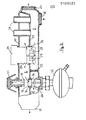
- FIG. 1 shows a connection device, the housing interior is divided into three chambers by an essentially horizontal partition 1 and two vertical partitions 2, 3.
- the threaded connection 4 leading to the first chamber A is provided for connecting the flow line coming from the district heating network.
- the incoming hot water flows in the direction of the arrow from above into the filter insert 5 which is open there and which can be designed as a cylindrical wire mesh.
- the dirt remains inside the filter insert 5 and the cleaned water then penetrates into the chamber B. So that the filter insert can be cleaned occasionally, a screw cap 6 is provided, from which the filter insert 5 can be removed. In the area of the open end 7, the filter insert 5 is only inserted into an opening 8 located in the partition 1.
- a further opening 9 is provided, into which a pipe section 10 is inserted.
- the pipe section 10 can be welded to the partition 1, soldered or fastened by means of an interference fit.
- the water flowing from chamber A to chamber B can reach chamber C via pipe section 10.
- the chamber B is actually divided into two sub-chambers which are connected to one another via a connection opening 11.
- the lower end of the pipe section 10 is designed as a valve seat 12 which interacts with the valve plate 13 of a pressure reducer 14.
- the pipe section 10 is thus part of the pressure reducer 14 in terms of its function.
- the pressure reducer 14 is arranged axially to the pipe section 10 and is fastened to the housing 15 of the connecting device. It essentially consists of a drive and control unit which can axially shift the valve plate 13 depending on the pressure present in each case.
- connecting pieces 16 are shown, which of course can be used in large numbers for the connection of sensors, valves, etc.
- an integrated safety valve 17 is indicated, which is guided through the housing 15 to the partition 1.
- Two connections 18 and 19 are provided for connection to the in-house installation.
- connection device shown in FIG. 2 is also divided into a plurality of chambers D, E, F in the interior of the housing by a horizontal partition wall 21 and by a vertical partition wall 22.
- This connection device is intended for installation in the return line and forms the interface between the heating system and the district heating.
- the heat transfer medium or the heating water passing through the heating system enters the chamber D.
- a heat meter 24 which passes through the housing 25 is inserted into an opening 26 in the partition 21, the water flows into the chamber E.
- the water flows into the lower part 27 of the heat meter 24, where it drives a counter 28. In the central area 29, the water then flows from the heat meter 24 into the chamber E.
- a pipe section 30 is inserted into the partition wall 21, through which the heat transfer medium flows in the direction indicated by the arrow.
- a quantity throttle 31 is arranged at the top and a quantity limiter with a differential pressure regulator 32 is arranged at the bottom.
- the two ends 33 and 34 of the pipe section 3o each form a valve seat, the upper of which cooperates with the valve plate 35 of the flow restrictor 31 and the lower one with the valve plate 36 of the flow limiter 32.
- the function of the built-in devices - heat meter 24, flow restrictor 31, flow limiter 32 - are identical to conventional devices. Since these devices are integrated in the connection device, they do not need their own housing, do not have to be connected by complex installation work and are arranged in an extremely space-saving manner. Such an arrangement is much easier to insulate against heat radiation than was the case with previous transfer stations.
- the entire connection device can be prefabricated industrially, and the valve seats formed by the pipe section 30 are extremely simple to manufacture. It is also pointed out that a transfer station, which can essentially consist of the two connection devices of FIGS. 1 and 2, has reproducible properties, ie each transfer station produced in this way has essentially the same properties. In transfer stations where the various fittings and devices are connected to each other via individual pipes, different properties occur depending on the line routing.
- the connecting piece 37 inserted into the partition 21 can be used to hold sensors such as pressure gauges, heat quantity sensors and thermometers. Of course, more connection pieces can be provided than shown in the drawing.
- the connection 38 can be connected, for example, to the return line of the heating coil leading through a hot water tank.
- the connection 39 provided on the left side of the connection device is connected to the return line of the district heating network.
Landscapes
- Engineering & Computer Science (AREA)
- Physics & Mathematics (AREA)
- Thermal Sciences (AREA)
- Chemical & Material Sciences (AREA)
- Combustion & Propulsion (AREA)
- Mechanical Engineering (AREA)
- General Engineering & Computer Science (AREA)
- Steam Or Hot-Water Central Heating Systems (AREA)
- Central Heating Systems (AREA)
- Resistance Heating (AREA)
Priority Applications (1)
| Application Number | Priority Date | Filing Date | Title |
|---|---|---|---|
| AT83111125T ATE32627T1 (de) | 1982-11-10 | 1983-11-08 | Fernheizungsanlage mit anschlussvorrichtung. |
Applications Claiming Priority (2)
| Application Number | Priority Date | Filing Date | Title |
|---|---|---|---|
| DE3241536 | 1982-11-10 | ||
| DE19823241536 DE3241536A1 (de) | 1982-11-10 | 1982-11-10 | Anschlussvorrichtung fuer heizungsanlagen |
Publications (3)
| Publication Number | Publication Date |
|---|---|
| EP0109032A2 true EP0109032A2 (fr) | 1984-05-23 |
| EP0109032A3 EP0109032A3 (en) | 1985-06-05 |
| EP0109032B1 EP0109032B1 (fr) | 1988-02-24 |
Family
ID=6177758
Family Applications (1)
| Application Number | Title | Priority Date | Filing Date |
|---|---|---|---|
| EP83111125A Expired EP0109032B1 (fr) | 1982-11-10 | 1983-11-08 | Installation de chauffage à distance avec un dispositif de raccordement |
Country Status (3)
| Country | Link |
|---|---|
| EP (1) | EP0109032B1 (fr) |
| AT (1) | ATE32627T1 (fr) |
| DE (1) | DE3241536A1 (fr) |
Cited By (5)
| Publication number | Priority date | Publication date | Assignee | Title |
|---|---|---|---|---|
| EP1441160A3 (fr) * | 2003-01-27 | 2004-08-25 | Bürkert Werke GmbH & Co. KG | Ensemble de clapets |
| WO2007066135A3 (fr) * | 2005-12-09 | 2007-11-29 | Ec Power As | Distributeur de fluide |
| GB2443341A (en) * | 2005-12-09 | 2008-04-30 | Ec Power As | Dividing plate for manifold with elongate chambers |
| NL1037883C2 (en) * | 2010-04-13 | 2011-10-17 | Jvb Beheer B V | Pump module for use in a manifold for a floor heating system. |
| WO2019123308A1 (fr) * | 2017-12-20 | 2019-06-27 | Rbm Ibox S.R.L. | Collecteur pour la distribution d'un fluide caloporteur dans un réseau de chauffage et/ou de refroidissement et/ou de climatisation, en particulier de type domestique et/ou industriel |
Families Citing this family (4)
| Publication number | Priority date | Publication date | Assignee | Title |
|---|---|---|---|---|
| DE3810739C1 (en) * | 1988-03-30 | 1989-04-06 | Iwk Regler Und Kompensatoren Gmbh, 7513 Stutensee, De | Safety device for a distant-heating transfer station |
| DE4105812A1 (de) * | 1991-02-23 | 1992-09-10 | Karl Lausser Gmbh | Gehaeuse fuer doppelkammer-verteiler |
| DE19633930A1 (de) | 1996-08-22 | 1998-02-26 | Kermi Gmbh | Monolithischer Wärmespeicherschrank |
| CN110975389A (zh) * | 2019-12-16 | 2020-04-10 | 浙江巨丰管业有限公司 | 一种地暖安装用带有过滤功能的集水装置 |
Family Cites Families (6)
| Publication number | Priority date | Publication date | Assignee | Title |
|---|---|---|---|---|
| NL6708548A (fr) * | 1966-06-28 | 1967-12-29 | ||
| DE2618896A1 (de) * | 1976-04-29 | 1977-11-17 | Bosch Gmbh Robert | Einrichtung zum anschliessen einer gebaeudeheizungsanlage an ein fernwaermenetz |
| DE2734553B1 (de) * | 1977-07-30 | 1978-11-23 | Hans Viessmann | Installationsblock fuer einen Fluessigkeitserhitzer |
| DE3008788A1 (de) * | 1980-03-07 | 1981-09-17 | Thermoval Fußbodenheizungen Entwicklungs- und Forschungsgesellschaft mbH, 1150 Wien | Heizungsverteiler |
| DE3214775C2 (de) * | 1982-04-21 | 1986-09-25 | IWK Regler und Kompensatoren GmbH, 7513 Stutensee | Vorrichtung zum Übergeben von wärmeführenden Fluid von einer Versorgungsleitung eines Fernheizkraftwerks zu einem Abnehmer |
| DE8212803U1 (de) * | 1982-05-04 | 1983-10-27 | Klinger AG, 6301 Zug | Hausinstallationseinheit fuer fernwaermebezug |
-
1982
- 1982-11-10 DE DE19823241536 patent/DE3241536A1/de active Granted
-
1983
- 1983-11-08 AT AT83111125T patent/ATE32627T1/de not_active IP Right Cessation
- 1983-11-08 EP EP83111125A patent/EP0109032B1/fr not_active Expired
Cited By (9)
| Publication number | Priority date | Publication date | Assignee | Title |
|---|---|---|---|---|
| EP1441160A3 (fr) * | 2003-01-27 | 2004-08-25 | Bürkert Werke GmbH & Co. KG | Ensemble de clapets |
| WO2007066135A3 (fr) * | 2005-12-09 | 2007-11-29 | Ec Power As | Distributeur de fluide |
| GB2443341A (en) * | 2005-12-09 | 2008-04-30 | Ec Power As | Dividing plate for manifold with elongate chambers |
| GB2443341B (en) * | 2005-12-09 | 2008-10-01 | Ec Power As | Fluid distributor |
| NL1037883C2 (en) * | 2010-04-13 | 2011-10-17 | Jvb Beheer B V | Pump module for use in a manifold for a floor heating system. |
| EP2378211A3 (fr) * | 2010-04-13 | 2016-06-01 | JFO Beheer B.V. | Module de pompe destiné à être utilisé dans un bloc de distribution pour des systèmes de chauffage par le sol |
| WO2019123308A1 (fr) * | 2017-12-20 | 2019-06-27 | Rbm Ibox S.R.L. | Collecteur pour la distribution d'un fluide caloporteur dans un réseau de chauffage et/ou de refroidissement et/ou de climatisation, en particulier de type domestique et/ou industriel |
| CN111684207A (zh) * | 2017-12-20 | 2020-09-18 | R.B.M.爱盒子有限责任公司 | 用于在特别地家用和/或工业类型的加热和/或冷却和/或调节网络中分配传热流体的收集器 |
| CN111684207B (zh) * | 2017-12-20 | 2022-04-29 | R.B.M.爱盒子有限责任公司 | 用于在特别地家用和/或工业类型的加热和/或冷却和/或调节网络中分配传热流体的收集器 |
Also Published As
| Publication number | Publication date |
|---|---|
| EP0109032A3 (en) | 1985-06-05 |
| DE3241536A1 (de) | 1984-05-10 |
| DE3241536C2 (fr) | 1991-02-14 |
| EP0109032B1 (fr) | 1988-02-24 |
| ATE32627T1 (de) | 1988-03-15 |
Similar Documents
| Publication | Publication Date | Title |
|---|---|---|
| DE2808854C2 (de) | Mit Einbauten versehener Strömungskanal für ein an einem indirekten Austausch, insbesondere Wärmeaustausch, beteiligtes Medium | |
| DE60007116T2 (de) | Baueinheit für eine sammelleitung eines versorgungsnetzes und befestigungssystem für solche baueinheiten | |
| EP0461073B1 (fr) | Dispositif d'oxydation par voie humide | |
| DE2116982C3 (de) | RohrleitungsVerteileranlage für Vor- und Rücklaufleitungen, insbesondere für Warmwasser-Heizungsanlagen | |
| EP0092032B1 (fr) | Dispositif pour transférer la chaleur d'un conduit de distribution à un consommateur | |
| EP0109032B1 (fr) | Installation de chauffage à distance avec un dispositif de raccordement | |
| DE3002712C2 (fr) | ||
| DE1814146A1 (de) | Schalldaempfer | |
| EP2180226A1 (fr) | Système de distribution de fluide modulaire | |
| DE202008014269U1 (de) | Modulares Fluidverteilsystem | |
| EP0445337B1 (fr) | Radiateur | |
| DE3914770C2 (fr) | ||
| DE4305694A1 (de) | Verteileraggregat für mit einem strömungsfähigen Wärmeträgermedium arbeitende Heiz- oder Kühlanlagen | |
| EP0057850A2 (fr) | Echangeur de chaleur pour liquides | |
| AT392829B (de) | Anschlusseinrichtung fuer das anschliessen von heizkoerpern | |
| AT390661B (de) | Anschlusseinrichtung fuer das anschliessen von heizkoerpern | |
| EP0244597A1 (fr) | Dispositif de transfert hydraulique de corps et emploi de ce dispositif | |
| DE29607030U1 (de) | Prüfanlage | |
| DE2625449C3 (fr) | ||
| DE102005048838A1 (de) | Wärmetauscher | |
| DE3320012A1 (de) | Waermetauscher, insbesondere fuer lueftungs- und klimaanlagen | |
| DE102019110073A1 (de) | Strömungswiderstandseinsatz und Durchflussmess- oder Durchflussregeleinrichtung | |
| EP0814294A1 (fr) | Dispositif de raccordement | |
| DE3136866C2 (de) | Röhrenwärmetauscher mit Strömungsleiteinbauten | |
| DE1679427C (de) | Meß und Regeleinrichtung fur an Fernheizungen angeschlossene Gebäude |
Legal Events
| Date | Code | Title | Description |
|---|---|---|---|
| PUAI | Public reference made under article 153(3) epc to a published international application that has entered the european phase |
Free format text: ORIGINAL CODE: 0009012 |
|
| AK | Designated contracting states |
Designated state(s): AT CH FR LI |
|
| PUAL | Search report despatched |
Free format text: ORIGINAL CODE: 0009013 |
|
| AK | Designated contracting states |
Designated state(s): AT CH FR LI |
|
| RHK1 | Main classification (correction) |
Ipc: F24D 3/00 |
|
| 17P | Request for examination filed |
Effective date: 19850710 |
|
| GRAA | (expected) grant |
Free format text: ORIGINAL CODE: 0009210 |
|
| AK | Designated contracting states |
Kind code of ref document: B1 Designated state(s): AT CH FR LI |
|
| REF | Corresponds to: |
Ref document number: 32627 Country of ref document: AT Date of ref document: 19880315 Kind code of ref document: T |
|
| ET | Fr: translation filed | ||
| PLBE | No opposition filed within time limit |
Free format text: ORIGINAL CODE: 0009261 |
|
| STAA | Information on the status of an ep patent application or granted ep patent |
Free format text: STATUS: NO OPPOSITION FILED WITHIN TIME LIMIT |
|
| 26N | No opposition filed | ||
| PGFP | Annual fee paid to national office [announced via postgrant information from national office to epo] |
Ref country code: FR Payment date: 19970929 Year of fee payment: 15 |
|
| PG25 | Lapsed in a contracting state [announced via postgrant information from national office to epo] |
Ref country code: FR Free format text: LAPSE BECAUSE OF NON-PAYMENT OF DUE FEES Effective date: 19990730 |
|
| REG | Reference to a national code |
Ref country code: FR Ref legal event code: ST |
|
| PGFP | Annual fee paid to national office [announced via postgrant information from national office to epo] |
Ref country code: AT Payment date: 20021113 Year of fee payment: 20 |
|
| PGFP | Annual fee paid to national office [announced via postgrant information from national office to epo] |
Ref country code: CH Payment date: 20021115 Year of fee payment: 20 |
|
| PG25 | Lapsed in a contracting state [announced via postgrant information from national office to epo] |
Ref country code: LI Free format text: LAPSE BECAUSE OF EXPIRATION OF PROTECTION Effective date: 20031107 Ref country code: CH Free format text: LAPSE BECAUSE OF EXPIRATION OF PROTECTION Effective date: 20031107 |
|
| PG25 | Lapsed in a contracting state [announced via postgrant information from national office to epo] |
Ref country code: AT Free format text: LAPSE BECAUSE OF EXPIRATION OF PROTECTION Effective date: 20031108 |
|
| REG | Reference to a national code |
Ref country code: CH Ref legal event code: PL |