EP0501478A2 - Magnetisches Detektionssystem mit verteilter konstanter Schaltung - Google Patents
Magnetisches Detektionssystem mit verteilter konstanter Schaltung Download PDFInfo
- Publication number
- EP0501478A2 EP0501478A2 EP92103368A EP92103368A EP0501478A2 EP 0501478 A2 EP0501478 A2 EP 0501478A2 EP 92103368 A EP92103368 A EP 92103368A EP 92103368 A EP92103368 A EP 92103368A EP 0501478 A2 EP0501478 A2 EP 0501478A2
- Authority
- EP
- European Patent Office
- Prior art keywords
- magnetic field
- magnetic
- distributed
- constant circuit
- detected
- Prior art date
- Legal status (The legal status is an assumption and is not a legal conclusion. Google has not performed a legal analysis and makes no representation as to the accuracy of the status listed.)
- Granted
Links
Images


Classifications
-
- G—PHYSICS
- G01—MEASURING; TESTING
- G01R—MEASURING ELECTRIC VARIABLES; MEASURING MAGNETIC VARIABLES
- G01R33/00—Arrangements or instruments for measuring magnetic variables
- G01R33/02—Measuring direction or magnitude of magnetic fields or magnetic flux
-
- G—PHYSICS
- G11—INFORMATION STORAGE
- G11B—INFORMATION STORAGE BASED ON RELATIVE MOVEMENT BETWEEN RECORD CARRIER AND TRANSDUCER
- G11B5/00—Recording by magnetisation or demagnetisation of a record carrier; Reproducing by magnetic means; Record carriers therefor
- G11B5/127—Structure or manufacture of heads, e.g. inductive
- G11B5/33—Structure or manufacture of flux-sensitive heads, i.e. for reproduction only; Combination of such heads with means for recording or erasing only
Definitions
- the present invention relates to a distributed-constant circuit type magnetic field detector for detecting an external magnetic field working on a novel principle and suitable for use, for example, in a magnetic reproducing head which detects a signal magnetic field from a magnetic recording medium such as a magnetic tape, a magnetic disk, and a floppy disk.
- the increase in the recording density is lowering the relative speed between the magnetic reproducing head and the recording medium.
- the reproduced output power by the inductive reproducing head is becoming extremely lower.
- the MR head is that of a magnetic flux sensitive type not dependent on its relative speed with the magnetic recording medium. Since the reproduced output by it is proportional to the current passed through the MR element, it is expected theoretically that the voltage will become higher the larger the current is. In practice, however, there is an upper limit to it because of heat to be produced by the current flow. On the other hand, since the reproduced output power is proportional also to the MR ratio of the MR element, materials having greater MR ratio are being intensively searched for. At present, Permalloy is being used chiefly, but its reproducing output power is not sufficient because its MR ratio is not higher than 2% or so. Besides, there is a big problem with the MR head that it produces Barkhausen noise to deteriorate the S/N ratio.
- a magnetic reproducing head of a magnetic flux sensitive type As another magnetic reproducing head of a magnetic flux sensitive type, there is proposed a magnetic reproducing head utilizing a change in the resonance characteristic of a coil by an external magnetic field (for example, Preprints for Spring National Conference of the Institute of Electronics, Information and Communication Engineers, 1990, pp. 5 - 35).
- this proposed head is not adapted to be a distributed-constant circuit and, further, permeability of the magnetic member used therein is in the frequency domain under 1 GHz.
- An object of the present invention is to provide a magnetic field detector functioning with high sensitivity and excellent high-frequency characteristics.
- a distributed-constant circuit type magnetic field detector which comprises a magnetic member whose permeability varies with changes in a magnetic field applied thereto disposed at a point where a magnetic field is produced in a distributed-constant circuit excited with an electromagnetic wave and means for detecting a change in electromagnetic field distribution in the distributed-constant circuit produced by a variation in permeability of the magnetic member upon application thereto of a magnetic field to be detected, whereby the magnetic field to be detected is detected.
- the present invention makes it possible to achieve magnetic reproduction, i.e., magnetic detection, with high sensitivity and excellent high-frequency characteristics. When applied to a magnetic reproducing head, it can effectively meet the demand for magnetic recording of higher packing density and at higher frequency.
- the present invention is directed to the provision of a distributed-constant circuit type magnetic field detector capable of detecting external magnetic field, namely, detecting existence or nonexistence and intensity of an external magnetic field, and, more particularly, detecting with high sensitivity a signal magnetic field generated by magnetic record made on a magnetic recording medium and forming a magnetic reproducing head meeting the demand for achievement of higher packing density and performance at higher frequency.
- the basic structure of the present invention is such that has a magnetic member 2, of which permeability ⁇ (the permeability herein refers to complex permeability) varies with changes in external magnetic field applied thereto, disposed at a point where a magnetic field is generated in the circuit of a distributed constant circuit 1 excited with an electromagnetic wave.
- permeability ⁇ the permeability herein refers to complex permeability
- the magnetic member 2 is set up at a point where a magnetic field is generated when the distributed-constant circuit 1 incorporating the magnetic member 2 is excited by an oscillator 3.
- a magnetic field to be detected is directly or indirectly applied to the magnetic member 2, whereby the permeability of it is varied, and the change in the electromagnetic field distribution in the distributed-constant circuit 1 due to the variation in the permeability is detected, and thus the magnetic field to be detected is detected.
- the distributed-constant circuit 1 including the magnetic member 2 in the above described basic structure has its terminal specially arranged to be impedance-unmatched so that a standing wave is produced.
- the standing wave voltage dependent on a change in the magnetic field to be detected applied to the magnetic member 2 is amplitude-detected at a point of the distributed-constant circuit 1, where the standing wave voltage exhibits its substantially minimum value (a point of node) under the condition of no magnetic field to be detected applied thereto, and thereby, the detection of the magnetic field to be detected is achieved.
- At least a portion of the distributed-constant circuit 1 in the above described basic structure is provided with a distributed-constant resonator.
- a magnetic member 2 is disposed at a point where a magnetic field is generated within the distributed-constant resonator. A change in the resonance characteristic of the resonator due to a variation in the permeability of the magnetic member 2 dependent on the magnetic field to be detected applied to the magnetic member 2 is detected and, thereby, detection or measurement of the magnetic field to be detected is achieved.
- the circuit in the above described basic structure has the magnetic member 2 provided with a magnetic yoke conducting the magnetic field to be detected such that a magnetic circuit including the magnetic member 2 is formed.
- a distributed-constant circuit 1 has a magnetic member whose permeability varies upon application of an external magnetic field disposed in the vicinity of its terminal portion and, in addition, the terminal portion is short-circuited.
- a magnetic member 2 whose permeability is varied upon application of the magnetic field to be detected at the terminal portion of a coplanar waveguide line or a coplanar line, and the change in the reflection coefficient at the terminal portion due to the variation of the permeability is detected, and thereby, the detection of the magnetic field to be detected is achieved.
- a magnetic member 2 whose permeability is varied upon application of the magnetic field to be detected at the terminal portion of the above coplanar waveguide line or the coplanar line, and it is adapted such that the variation in the permeability thereof at a frequency within the range from 1 Ghz to 10 GHz is utilized.
- a coplanar line having a portion in which the line width is gradually increased while the ratio between conductor width and conductor spacing is kept constant is used as the above coplanar waveguide line or coplanar line.
- the coplanar waveguide line or coplanar line has the top surface covered with a dielectric member.
- a D.C. current is passed through the above coplanar waveguide line or coplanar line so that a bias magnetic field is applied to the magnetic member 2.
- the distributed-constant circuit 1 when the distributed-constant circuit 1, or, in concrete terms, a distributed-constant circuit 1 of a microstrip line, a waveguide, a coaxial cable, or the like, is exited by the oscillator 3, a progressive wave is generated if the terminal. i.e., the load terminal, is in an impedance-matched state, and a reflected wave is produced in addition to the progressive wave if the terminal is in an impedance-unmatched state, so that a standing wave is produced by superposition of the progressive and reflected waves.
- the standing-wave ratio is maximized when the terminal of the distributed-constant circuit 1 is open or short-circuited.
- a distributed-constant circuit 1 including a magnetic member 2 whose permeability varies with changes in a magnetic field applied thereto, and the magnetic member 2 is disposed at the point in the circuit where a magnetic field is generated when it is put in an oscillating state.
- the permeability ⁇ real part ⁇ r and imaginary part ⁇ i
- the voltage distribution shown in FIG. 1B is also varied. Therefore, the magnetic field to be detected can be detected by detecting, for example, phase, amplitude, or wavelength at a specific point x s of the distributed-constant circuit 1.
- the curve 4Z in FIG. 2 shows a waveform of a standing wave of which the standing-wave amplitude
- exhibits its minimum value V0 at the specific point x s , under the condition of an external magnetic field H ex being not applied, i.e., H ex 0, for example, and the terminal of the distributed-constant circuit 1 being in an unmatched state.
- H ex an external magnetic field
- H ex the ratio between the maximum value and the minimum value of the standing-wave amplitude
- ⁇ denotes the standing-wave wavelength
- ⁇ /2 denotes the interval at which the crests or the troughs of the standing wave cycle.
- the standing-wave ratio is maximized when the terminal is open or short-circuited.
- the distributed-constant circuit 1 is formed of a distributed-constant resonator and the magnetic member 2 is disposed within the resonator to provide another arrangement of the present invention
- the electromagnetic wave satisfying the resonance condition is excited within the resonator. Therefore, the variation in the permeability of the magnetic member 2 gives a great effect on the resonance characteristic to change the resonance wavelength and resonance amplitude (the value Q), and thereby the state of excitation of the electromagnetic wave within the resonator is greatly changed leading to a great change in the electromagnetic-wave distribution in the distributed-constant circuit 1.
- detection of the magnetic field to be detected can be achieved with higher sensitivity.
- the magnetic member 2 when it is arranged such that the magnetic member 2 is magnetically coupled with a magnetic yoke and the magnetic field to be detected is introduced through the magnetic yoke, the magnetic field to be detected can be effectively applied to the magnetic member 2. Therefore, especially when the arrangement is applied to a reproducing magnetic head for reading the record on a magnetic recording medium, a high reproducing sensitivity can be obtained.
- the distributed-constant circuit 1 of the present invention as shown in FIG. 1A indicating its basic structure, comprises a distributed-constant circuit 1, or in concrete terms, a microstrip line, a coaxial cable, or the like, and it is adapted to be excited by an oscillator 3 through a microwave transmission line 10 such as a coaxial cable.
- the distributed-constant circuit 1 is arranged to incorporate a magnetic member 2 made of a soft magnetic material, such as CoTaZr amorphous, whose permeability ⁇ , the real part ⁇ r or imaginary part ⁇ i , varies with changes in the magnetic field applied thereto.
- a magnetic member 2 made of a soft magnetic material, such as CoTaZr amorphous, whose permeability ⁇ , the real part ⁇ r or imaginary part ⁇ i , varies with changes in the magnetic field applied thereto.
- the position where the magnetic member 2 is disposed is selected at a point where a strong magnetic field is generated when the distributed-constant circuit 1 incorporating the same is excited.
- the distributed-constant circuit 1 can have its terminal, or the so-called load terminal, in either of a matched state and an unmatched state.
- the terminal When the terminal is in the matched state, there is produced a progressing wave, and when it is in the unmatched state, there is produced a standing wave by generation of the reflected wave as described above.
- the standing-wave ratio becomes great.
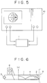
- FIG. 3 is a schematic structural drawing of an example of the present invention applied to a magnetic reproducing head for reading a record signal on a magnetic recording medium 5.
- the magnetic member 2 made of the above described soft magnetic material whose permeability varies with changes in the magnetic field applied thereto is disposed for example at the terminal portion of the distributed-constant circuit 1, and the same is arranged to be closely confronted with the magnetic recording medium 5 and moved relative to the medium 5 so that a leakage signal magnetic field from the record magnetization on the medium 5 is applied to the magnetic member 2 to thereby cause a variation in its permeability.
- a change in the electromagnetic field distribution due to the variation in the permeability caused by the signal magnetic field is measured as, for example, a change in voltage, or a change in amplitude or phase, at a specific point in the distributed-constant circuit 1 by a detector 6, such as a network analyzer, and/or a rectifier plus a voltmeter.
- FIG. 4 is a diagram showing an arrangement in which the reflection coefficient S11 of a distributed-constant circuit 1 is measured by a network analyzer 61 and
- FIG. 5 is a diagram showing an arrangement in which the transmission coefficient S21 is measured.
- the voltage distribution of the standing wave produced when the circuit is excited becomes as shown by the curve a in FIG. 6, that is, the voltage is minimized at the terminal where a node is formed. Therefore, the current is maximized at the terminal and the generated magnetic field is maximized at the terminal. Accordingly, the distribution of the standing wave is most strongly affected by the permeability at the terminal portion.
- the standing wave is most strongly affected by the change in the external magnetic field.
- the detector of FIG. 6 when using the detector of FIG. 6 as a magnetic reproducing head and the terminal of the distributed-constant circuit 1 is directly held close to a magnetic recording medium 5 to detect the signal magnetic field from the medium 5, it is preferred to have the magnetic member disposed at the terminal.
- the electric field generated at the terminal portion is decreased as described above. Therefore, the change in the admittivity at the terminal portion produces little effect on the standing-wave distribution. Accordingly, noise to be produced by electrical causes when the terminal is brought closer to the magnetic recording medium 5 can be reduced.
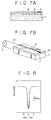
- the distributed-constant circuit 1 in the present invention can be provided by a microstrip type arrangement for example as show in FIG. 7.
- the circuit is structured of a line conductor 9 made of Au, Cu, or the like in a strip form disposed on a ground conductor 7 made of Au, Cu, or the like through a dielectric member 8 made of glass, Al2O3, sapphire, or similar material whose permittivity is high and high-frequency loss is low and through, at its portion on the terminal side, a magnetic member 2 made of an amorphous soft magnetic thin film of Co75Ta11Zr14, and the line conductor 9 and the ground conductor 7 are short-circuited at the terminal.
- the line conductor was 30 ⁇ m wide and 1 ⁇ m thick
- the magnetic member 2 was 1 mm long, 30 ⁇ m wide, and 0.5 ⁇ m thick.
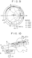
- the dependency on the external magnetic field of the impedance of the distributed-constant circuit 1 of the above described structure was measured using a network analyzer (HP8719A made by Hewlett-Packard Corp.) within the range of frequencies f from 130 MHz to 8 GHz.
- the test results are shown in FIG. 9.
- the input impedance of the waveguide line hence the electromagnetic-wave distribution in the waveguide line, is dependent on the external magnetic field H ex .
- the external magnetic field i.e., the magnetic field to be detected H ex .
- FIG. 10 a case where a microstrip line type structure is used will be described below in detail. Parts in FIG. 10 corresponding to those in FIG. 7 are denoted by like reference numerals.
- the structure has a ground conductor 7 and a line conductor 9 with for example a dielectric member 8 and a magnetic member 2 interposed therebetween.
- a dielectric member 8 formed of a substrate of Al2O3, sapphire, or a similar material whose permittivity is high and high-frequency loss is low is prepared and a thin film 2s of an amorphous soft magnetic material Co75Ta11Zr14 of a thickness of 0.7 ⁇ m, for example, is deposited on the substrate by sputtering.
- the permeability ⁇ of the thin film 2s of the soft magnetic material exhibits a sharp magnetic-field dependency
- it is heat-treated under application of a fixed magnetic field of 1 kOe, for example, in a temperature of 300°C for one hour, whereby it is provided with uniaxial anisotropy of an anisotropic magnetic field Hk of approximately 0.2 (Oe), for example.
- a good conductive layer not shown, of a material with good conductivity such as Au or Cu is deposited to a thickness of 1 ⁇ m by sputtering.
- the good conductive layer, together with the underlying soft magnetic material thin film 2s, is subjected to pattern etching by photolithography into a strip form for example with a length of 2 mm and a width of 30 ⁇ m, while having the axis of easy magnetization e.a of the soft magnetic material thin film 2s virtually aligned in the lateral direction.
- a line conductor 9 in a strip form made of a good conductive Cu layer is formed and, at the same time, a magnetic member 2, which is formed of a portion of the soft magnetic material thin film 2s and permeability of which is dependent on the external magnetic field, is formed underlying the conductive layer.
- the dielectric member 8 with the magnetic member 2 and the line conductor 9 formed thereon is joined to a block with good conductivity such as a Cu block constituting the ground conductor 7.
- an oscillator 3 i.e., a high-frequency power source, is connected between the line 9 and the ground conductor 7 through a transmission line 10 formed for example of a coaxial cable.
- the magnetic field can be detected as a change between V0 and V ex .
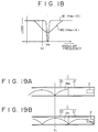
- FIG. 12 is a transverse sectional view of the microstrip line forming the distributed-constant circuit 1.
- the thin lines a1, a2, a3, ... indicate distribution of the magnetic field
- the thin broken lines b1, b2, b3, ... indicate distribution of the electric field.
- the magnetic field is generated in the lateral direction of the line conductor 9. Therefore, when the magnetic member 2 having its axis of easy magnetization e.a in the lateral direction is placed there, the permeability ⁇ with respect to the lateral magnetic field generated by the microwave can be changed by application of the external magnetic field H ex along the axis of difficult magnetization. As a result, the standing-wave ratio and/or the standing-wave amplitude ⁇ is changed.
- the detector, i.e., magnetic head, of the above described structure is brought into position, as described with reference to FIG. 3, such that the load terminal (open terminal) 1a of the microstrip type distributed-constant circuit 1 is closely confronted with a magnetic recording medium (not shown) so as to detect a leakage magnetic field from the record on the magnetic recording medium, i.e., a signal magnetic field, as the external magnetic field H ex .
- a leakage magnetic field from the record on the magnetic recording medium i.e., a signal magnetic field, as the external magnetic field H ex .
- the magnetic signal can be taken out by being converted to an electric signal.
- the permeability of the magnetic member 2 in the direction of its axis of easy magnetization is small when no external magnetic field H ex is applied thereto in the direction perpendicular to its axis of easy magnetization, but it gradually increases as the magnetic field in the direction perpendicular to the axis of easy magnetization is applied thereto and gradually increased.
- the carrier frequency f is set to 1 GHz, for example, and even though the frequency of the record signal magnetic field H ex is set to such a sufficiently high frequency as about 100 MHz being one digit lower than the carrier frequency, the carrier component can be removed by amplitude-detection by means of the rectification circuit 62 and only the change in H ex can be taken out as a voltage change.
- FIG. 13 shows the output voltage V D of the detector circuit measured against changing external magnetic field H ex under the condition of the above described arrangement being applied with no bias magnetic field.
- a bias magnetic field application means 11 of an electromagnet or a permanent magnet is disposed as shown in FIG. 10 so that the center of operation is brought to the point B1 or B2 where the magnetic-field dependency of V D is the steepest and good in linearity.
- the magnetic member 2 was of the structure included in the waveguide line formed of a microstrip line, the magnetic member 2 can be arranged as a portion of, or in place of, the dielectric member 8 when the magnetic member 2 has an insulating (dielectric) property, or it can be arranged as a portion of, or in place of, the conductor 7 or 9 when it has good conductivity.
- the magnetic member 2 described with reference to FIG. 10 was made in a strip form and its axis of easy magnetization e.a was set in the lateral direction, the orientation of the axis of easy magnetization and the intensity of anisotropic magnetic field can be selected according to the purpose or manner of its use.
- a magnetic yoke 12 which is formed of a soft magnetic member with high permeability in which a magnetic gap g is made as shown in FIG. 14, and dispose the magnetic member 2 in the magnetic path of the magnetic yoke 12.
- the magnetic yoke 12 When the magnetic yoke 12 is arranged as described above and the magnetic field to be detected is introduced through the gap g provided therein, the degree of freedom in selecting the position, form, and the like of the magnetic member 2 is made larger. Hence, the position, form, etc. of the magnetic member 2 can be set up so that the electromagnetic field in the distributed-constant circuit 1 is most greatly affected by it. Hence, the sensitivity can be improved. Further, the efficiency of application of the external magnetic field, i.e., the magnetic field to be detected, to the magnetic member 2 can be improved, whereby still higher sensitivity can be obtained.
- the leakage magnetic field from the record magnetization on the medium 5, i.e., the record signal magnetic field, can be satisfactorily read by it with high resolution and high sensitivity.
- a magnetic yoke 12 including a magnetic gap g is magnetically coupled for example with a distributed-constant circuit 1 of the microstrip line type waveguide line of the structure described in FIG. 10.
- Parts in FIG. 15 corresponding to those in FIG. 10 and FIG. 14 are denoted by like reference numerals and explanation of the same will therefore be omitted.
- the distributed-constant circuit 1 of the apparatus of the present invention can also be structured such that a portion of it is provided by a distributed-constant resonator.
- the distributed-constant circuit 1 is constituted of a distributed-constant resonator 21 and an external circuit 22.
- the external circuit 22 is formed of a transmission line 10 connecting an oscillator 3 with the distributed-constant resonator 21 and a voltmeter 63, for example, as a detector 6 disposed at a specific point x1 of the transmission line 10.
- a magnetic member 2 whose permeability varies with changes in the external magnetic field H ex , i.e., the magnetic field to be detected, is disposed within the distributed-constant resonator 21.
- the magnetic member 2 is disposed for example at such a point where the internal magnetic field of the distributed-constant resonator 21 including the magnetic member 2 is as strong as possible when it is excited at the resonant frequency ⁇ 0 and where the external magnetic field H ex can be detected most advantageously.
- the resonator 21 when a reproducing magnetic head is formed with the above described arrangement, the resonator 21 will be disposed on the terminal side of the distributed-constant circuit 1 and the magnetic member 2 within the distributed-constant resonator 21 will be disposed on its terminal side and the terminal will be closely confronted with the magnetic recording medium 5 so that the signal magnetic field from the medium 5 as the magnetic field to be detected, i.e., the external magnetic field H ex , may be applied to the magnetic member 2.
- the distributed-constant circuit 1 As a means for structuring the distributed-constant resonator 21, there is a method to short-circuit the distributed-constant circuit 1 at the boundary between the portion desired to be used as the distributed-constant resonator 21 and the portion to be used as the external circuit 22.
- ⁇ r or ⁇ i varies with changes in the external magnetic field H ex .
- the magnetic member 2 can also be arranged to have the structure coupled with a magnetic yoke 12 as described for example in FIG. 14.
- the distributed-constant circuit type magnetic field detector according to the present invention can be formed into a reproducing magnetic head for reading a record signal on a magnetic recording medium 5, such as a magnetic tape, a magnetic sheet, and a magnetic disk, the same can further be formed into a recording and reproducing magnetic head by adding it a recording head function of an electromagnetic inductive type.
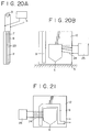
- FIG. 20A An example of adding a function of an electromagnetic inductive recording head to a reproducing head of a microstrip line type, for example, will be described with reference to a side view of FIG. 20A and a plan view of FIG. 20B.
- the above described magnetic member 2 of a soft magnetic material whose permeability varies with changes in the applied magnetic field is disposed on a ground conductor 7 made of Cu.
- a magnetic yoke 12 for example of magnetic ferrite coupled with the magnetic member 2 or that using the magnetic member 2 as its constituent, or that as a whole structured of the magnetic member 2 is provided.
- the magnetic yoke 12 forms a magnetic yoke 12 (magnetic core) of a C-shaped or U-shaped thin film with a magnetic gap g provided at its end portion.
- a line conductor 9 of a layer of Au, Cu, or the like shaped in a linear form as shown in the plan view of FIG. 20B or arranged in conformity with the pattern of the magnetic yoke 12 as shown in FIG. 21, such that a microstrip line is formed of the conductors 9 and 7.
- the microstrip line is short-circuited at the portion close to the gap where the magnetic field from the medium is at its maximum intensity.
- the magnetic yoke 12 is provided with a head winding 24, i.e., an electromagnetic induction winding.
- an insulating layer 23 of SiO2 or the like is interposed between the yoke 12 and each of the conductors 7 and 9.
- a current corresponding to a record signal from a recording signal source 25 is supplied to the head winding 24, under the condition of no high-frequency current being supplied from the oscillator 3, so that magnetic flux is generated in the magnetic yoke and the record magnetic field is produced from the magnetic gap g, and thereby, the magnetic recording is made on the magnetic recording medium 5 arranged before the same in contact or confrontation with it.
- the waveguide line is oscillated by means of the oscillator 3. Under this condition, the leakage magnetic flux of record magnetization from the magnetic recording medium 5 is given to the magnetic member 2 constituting the magnetic yoke 12 or a part of it through the gap g. Then, since the state of oscillation is changed by a variation in permeability of the magnetic member 2, detection of the magnetic field, hence, reading of the record on the magnetic recording medium, i.e., reproduction, can be achieved by performing for example voltage rectification or phase detection at a specific point of the waveguide line or transmission line using a detecting or measuring device 6 as described above.
- the sensitivity can be improved by forming a portion of the microstrip line into a distributed-constant resonator or the like as described above.
- the apparatus is formed with a ring resonator as shown in a plan view and a side view of FIGs. 22A and 22B, wherein a portion of a dielectric member 8 in an ordinary ring resonator is arranged by a ring-shaped magnetic yoke 12.
- a microstrip line 30 is formed of a ground conductor 7 with a large area with a line conductor 9 in a strip form provided on a portion thereof with a dielectric member 8 interposed therebetween.
- a ring-shaped thin-film magnetic yoke 12 magnetic core
- a line conductor 29 in a ring shape is formed thereon along the ring of the magnetic yoke 12, and thereby a ring resonator 31 is formed.
- the magnetic yoke 12 is conductive
- an insulating layer 23 is interposed between the magnetic yoke 12 and each of the conductors 7 and 29.
- the conductors 9 and 29 are patterns separated from each other, they are, so to say, in capacitive coupling with each other.
- the magnetic yoke 12 is provided with a head winding 24 round it.
- a record signal current is supplied to the head winding 24 from a record signal source 25, with the microstrip line 30 and the ring-shaped resonator 31 not excited, so that magnetic flux is passed through the magnetic yoke 12 and a magnetic recording medium 5 is magnetized for making record by the magnetic field from the gap g closely confronted with the magnetic recording medium 5.
- the ring resonator 31 is excited by the oscillator 3 through the microstrip line 30 and the permeability of the magnetic member 2 is varied according to signal magnetic flux from the record on the magnetic recording medium 5 introduced therein through the magnetic gap g, whereby the resonant characteristics of the resonator are changed. Then, for example a change in the voltage distribution depending on the change in the resonant frequency or change in Q, for example, is detected at a specific point, for example of the microstrip line or transmission line 8 as described with reference to FIG. 16 to FIG. 19.
- the size of the ring resonator 31 is determined depending on whether the variation in the real part ⁇ r or that in the imaginary part ⁇ i of the permeability ⁇ of the magnetic member 2 is utilized.
- a method to set the frequency slightly shifted from the resonant frequency may be used.
- FIG. 23 is a schematic perspective view of the example.
- a distributed-constant circuit 1 of a coaxial cable type comprises a center conductor 32, and a dielectric member 38 and a ground conductor 33 provided around the center conductor coaxially therewith.
- the terminal portion of the distributed-constant circuit 1 is for example short-circuited.
- FIG. 25 indicates the electric field distribution and the dotted line indicates the magnetic field distribution.
- a magnetic member 2 whose permeability varies with changes in magnetic filed is disposed in the position where the electric field distribution has its minimum value (namely, the position of node), i.e., the position where the magnetic field distribution has its maximum value (namely, the position of loop) as shown in FIG. 25 as well as in FIG. 23 and a transverse sectional view of the distributed-constant circuit 1 of FIG. 26.
- the magnetic member 2 is made in a ring-shaped plate form disposed between the center conductor 32 and the ground conductor 33 surrounding it, with its planar direction cutting the center conductor 32 at right angle and provided with a magnetic gap g cut at a portion of it in the radial direction.
- the magnetic gap g faces outward through a window made at a portion of the ground conductor 33 and is adapted to be closely confronted with a magnetic recording medium 5.
- the magnetic member 2 can be formed of a ring-shaped CoTaZr plate as described above or provided by depositing a CoTaZr thin film on an insulating substrate.
- an insulating layer 23 is interposed between the magnetic member 2 and each of the conductors 32 and 33 as shown in FIG. 26.
- the size of the window 34 can be made small enough as compared with the wavelength of the electromagnetic field exciting the distributed-constant circuit 1, and therefore, the effect of the window 34 on the excitation condition is negligible.
- a current corresponding to the record signal at a frequency on the order for example of 10 MHz from a record signal source 25 is passed for example between the center conductor 32 and the ground conductor 33, with the distributed-constant circuit 1 not excited, so that magnetic flux is generated in the ring-shaped magnetic member 2 and a record magnetic field is generated from its magnetic gap g, and the record is made, through the window 34, on the magnetic recording medium 5 closely confronted with the gap.
- the recording signal source 25 is cut off from the distributed-constant circuit 1, the distributed-constant circuit 1 is excited by the oscillator 3 as described in FIG. 25, and the magnetic gap g is brought to be closely confronted with the magnetic recording medium 5. Then, a magnetic field according to magnetization of the record signal on the magnetic medium 5 is applied from the magnetic gap g to the magnetic member 2, causing its permeability to vary. Thereby, the circular electromagnetic field in the distributed-constant circuit 1 is affected and the standing wave ratio, amplitude, etc. are changed. Then, by rectifying the voltage, for example, at a specific point of the transmission line 10, as shown in FIG. 23, or of the distributed-constant circuit 1, to thereby detect or measure a change in voltage, reading of the record signal on the magnetic recording medium 5, i.e., reproduction, can be achieved.
- FIG. 27 is a perspective view of another example of the distributed-constant circuit type magnetic field detector of the present invention applied to a magnetic reproducing head.
- a coplanar waveguide line is used as the microwave waveguide line.
- the apparatus in the present example comprises a coplanar waveguide line 70 being short-circuited at its terminal and having a thin film magnetic member 2 whose permeability varies with signal magnetic flux penetrating thereto, a microwave source, i.e., an oscillator 3, a rectification diode 71, and a voltmeter 63.
- the rectification diode 71 is covered with an insulating material and enclosed by a grounded shielding conductor.
- the coplanar waveguide line 70 is a type of microwave waveguide line and formed, as shown in FIG. 27, with a dielectric member 8 having good conductive layers of Au, Cu, or the like deposited thereon by patterning such that one layer serves as a line conductor 9 and the other layers on both sides thereof serve as ground conductors 7.
- FIG. 28A is a top view of the coplanar waveguide line 70 shown in FIG. 27, and FIG. 28B and FIG. 28C are sectional views taken along broken lines b and c in FIG. 27.
- a magnetic recording medium 5 In front of the terminal portion of the waveguide line 70 where the magnetic member 2 is provided, there is arranged a magnetic recording medium 5, from which a record signal is to be read out, so as to move in the direction indicated by the arrow d in sliding contact with or slightly separated from the terminal portion.
- the reflection coefficient at the terminal portion is determined dependent on the permeability of the thin film magnetic member 2 in the direction W1.
- the magnetic member 2 is provided with such magnetic anisotropy that the axis of easy magnetization is aligned with the direction W1
- the magnetization changes its orientation from the direction W1 to the direction L1 as the signal magnetic flux is injected into the same.
- the permeability in the direction W1 varies, and thus, the permeability can be greatly varied by a slight change in magnetic flux.
- FIG. 30 is a diagram showing results of measurement of the input impedance of the coplanar waveguide type magnetic reproducing head shown in FIG. 27 obtained by connecting the head to a network analyzer (HP8719A made by Hewlett-Packard Corp.).
- the range of frequencies at which the measurement was made was from 130 MHZ to 5 GHz.
- the broken line indicates the results when no external magnetic field is applied and the solid line indicates when an external magnetic field of 80 A/m is applied.
- Considerable changes in the input impedance (reflection coefficient) upon application of the external magnetic field are observed at the frequencies from 2.5 GHz to 4.5 GHz. It is generally considered that the permeability of magnetic materials sharply decreases in the high-frequency range and shows a very small value in the frequency range of several GHz.
- the results of measurement shown in FIG. 30 indicate that there is a frequency range within a high-frequency domain over 1 GHz where the permeability greatly varies under the application of external magnetic field.
- the operating frequencies can be set to 1 - 10 GHz.
- a required D.C. bias current may be applied between the line conductor 9 and the ground conductor 7. Then, by the current flow in the direction L1 through the line conductor 9 where the magnetic member 2 is disposed, a bias magnetic field perpendicular to it is applied to the magnetic member 2 in its lateral direction W1. Also by this means, a performance excellent in sensitivity and linearity can be obtained.
- the line of the short-circuited portion of the line conductor 9 and the ground conductor 7 at the terminal of the coplanar waveguide line 70 where the magnetic member 2 receives the strongest signal magnetic flux from the medium is divided into two directions.
- the magnetic field component of the microwave at this portion comes to deviate from its state uniformly aligned in the lateral direction of the line conductor 9.
- the change in the characteristic impedance of the waveguide line 70 exhibited when the permeability of the thin film magnetic member 2 is varied by the penetration of the signal flux becomes smaller.
- the width of the short-circuiting line must be set below the record wavelength, but when it is made extremely narrow, electric resistance increases, loss increases, and sensitivity lowers.
- Such problem can be overcome by arranging the magnetic member 2 at the short-circuiting line portion 79 of the coplanar waveguide line 70 as shown in FIG. 32.
- the magnetic field is generated in the lateral direction of the short-circuiting line 79, i.e., in the direction L1, and therefore, the reflection coefficient depends on the permeability in the lateral direction of the magnetic member 2.
- the reflection coefficient at the terminal portion changes.
- the magnetization changes its orientation from the direction W1 to the direction L1 upon penetration of the signal magnetic flux, whereby the permeability in the direction L1 is effectively varied.
- a D.C. bias current between the ground conductors 7 having the line conductor 9 in between, i.e., through the short-circuiting line 79, to thereby apply a required bias magnetic field to the magnetic member 2 in its lateral direction (the direction perpendicular to the direction W1), the condition for obtaining excellent sensitivity and linearity as described above can be set up.
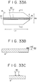
- FIG. 33A is a plan view of the coplanar line 90
- FIG. 33B and FIG. 33C are sectional views taken along line B - B and line C - C in FIG. 33A.
- the reflection coefficient depends on the permeability of the magnetic member 2 in the direction L2. If the magnetic anisotropy is provided for the magnetic member 2 such that its axis of easy magnetization is in the direction W2, the magnetization changes its orientation from the direction W2 to the direction L2 upon penetration of the signal magnetic flux, whereby the permeability in the direction L2 is varied. Further, by passing a required D.C. bias current between the line conductor 9 and the ground conductor 7, hence through the short-circuiting line 79, the magnetic member 2 can be provided with a bias magnetic field in the direction L2.
- the coplanar waveguide line 70 is fabricated by dividing it, for example, into a magneto-sensitive portion 701 and a rectification portion 702 as shown in FIG. 34.
- the magneto-sensitive portion 701 was fabricated in the following way.
- a glass substrate was used as the dielectric member 8 shown in FIG. 27.
- a line conductor 9 and a ground conductors 7 were formed by a photo process such that the magnetic member 2 underlies the terminal portion of the line conductor 9, as shown in an enlarged plan view of FIG. 34, and the line conductor 9 is 30 ⁇ m wide, the line conductor 9 and the ground conductor 7 are spaced a distance of 10 ⁇ m apart, the ground conductor 7 is 5 mm wide, the short-circuiting line 9 is 30 ⁇ m wide, and the waveguide line is 15 mm long.
- a cover glass 8' dielectric member
- the input terminal portion of the coplanar waveguide line 70 which is necessary for wire bonding, was left uncovered with the cover glass 8'.
- the product is cut along the waveguide line pattern using a diamond cutter.
- the glass at the terminal portion as shown in a further enlarged view of the terminal portion of FIG. 35, was ground with a grinding film so that the front end of the magnetic thin film may smoothly contact with a magnetic recording medium when the portion is brought into contact with the magnetic recording medium in magnetic reproduction, and thus the magneto-sensitive portion 701 was fabricated.
- the rectification portion 702 Cr was deposited onto a glass substrate 8 to a thickness of 50 nm by sputtering, and over the same, Au was deposited to a thickness of 1 ⁇ m, and thereafter, as show in FIG. 34, a line conductor 9 with a width of 1 mm was formed, a ground conductor 7 was formed a distance of 0.33 mm apart from the line conductor 9, and the waveguide line length was set to 2.0 mm by a photo process. At this time, the ratio between the width of the line conductor 9 and the distance between the line conductor 9 and the ground conductor 7 was made equal to that in the magneto-sensitive portion 701 to obtain equal characteristic impedance.
- the glass substrate 8 of the waveguide line was cut along the waveguide line pattern using a diamond cutter.
- one terminal of a schottky diode 71 for rectification was attached to the ground conductor 7 by conductive paste, solder, or the like.
- the schottky diode 71 was sheathed with a shielding conductor 72, as shown in FIG. 36, formed of an insulating layer 80 of an insulating film or the like surrounding the diode and a conductive film wound around the same, and the shielding conductor 72 was grounded.
- the point at which the diode 71 is connected to the line conductor 9 depends on the frequency of the introduced microwave and selected to be in the vicinity of a node of the standing wave produced.
- coaxial connectors 81 and 82 were attached to the product.
- the outer ground conductor of the coaxial connector 82 was connected with the ground conductor 7 of the coplanar waveguide line 70 and the center conductor was connected with the other terminal of the diode 71.
- the rectification portion 702 was fabricated.
- the magneto-sensitive portion 701 and the rectification portion 702 fabricated as described above were fixed in a suitable jig and, as shown in FIG. 34, the line conductors 9 in the center of both the portions were connected by wire bonding 83 and ground conductors 7 of them on both sides were connected by a conductive material 84 such as conductive paste or solder.
- a so-called taper line as shown in FIG. 37 can be used as the coplanar waveguide line 70 of the magneto-sensitive portion 701, in which taper line, the width of the line conductor 9 and the distance between the line conductor 9 and the ground conductor 7 are made to become gradually larger until they become equal to those of the rectification portion 702, while keeping the ratio between the width of the line conductor 9 and the distance between the line conductor 9 and the ground conductor 7 constant so that the characteristic impedance is kept unchanged.
- the above fabricating method of the coplanar waveguide line is equally applicable to the coplanar line 90.
- the ratios between the widths of the line conductor 9 and the ground conductor 7 and the distance therebetween are maintained constant.
- FIG. 30 described earlier is that showing the results of measurement of the input impedance obtained by connecting the coaxial connector 82 of the coplanar waveguide line 70 shown in FIG. 34 and FIG. 35 to the network analyzer (HP8719A made by Hewlett-Packard Corp.). Since the frequency at which the reflection coefficient, i.e., the permeability of the magnetic member 2, changes upon application of an external magnetic field H ex differs with the magnetic characteristic and magnetic material of the magnetic member 2, the frequency of the microwave used must be selected according to such factors.
- FIG. 39 shows dependency on magnetic field of the output voltage at the connector 82 rectified by the rectification diode 71 in the state where an oscillator 3 of a microwave source is connected to the coaxial connector 81 of FIG. 34 and FIG. 35 through a coaxial cable and a microwave at around a frequency of 3.6 GHz is input to the waveguide line.
- a change in the output voltage around 30 mV was observed upon application of a magnetic field around 100 A/m.
- reproduction of a signal recorded on a magnetic tape was performed according to a method shown in FIG. 40.
- a sine wave signal of 0.1 MHz was recorded on a magnetic recording medium 5 (magnetic tape) for VTR using an ordinary ring-shaped inductive magnetic head.
- a microwave at the frequency 3.6 GHz from an oscillator 3 is input to the waveguide line.
- a magnetic field ( ⁇ 30 A/m), which corresponds to the point where the rate of change in the output voltage to the change in the magnetic field, dV/dH, is at its maximum in FIG. 39, is applied to the thin film magnetic member 2 at the terminal portion as a bias magnetic field.
- the application of the bias magnetic field is achieved by providing a coil 92 as shown in the enlarged view of the terminal portion of the reproducing head in FIG. 41 and passing a current from a bias power source 93 or by arranging a permanent magnet in the vicinity of the terminal portion.
- the bias magnetic field can be supplied by passing D.C. current to the coplanar waveguide line or the coplanar line.
- the magnetic member 2 at the terminal of the head was arranged to be in contact with the magnetic tape for VTR and the voltage rectified by the diode 71 was detected by an oscilloscope 94.
- the results are shown in FIG. 42.
- an output of 20 mV p - p, two digits or so larger than obtained by an ordinary inductive head or an MR head was obtained.
- reference numeral 95 denotes a guide drum of a magnetic recording medium 5, i.e., of a magnetic tape in the present example, and 96 denotes its rotational driving motor.
- the magnetic field detector according to the present invention is not limited to the above illustrated examples but various changes and modifications can be made according to the purposes of use and manners of use.
- the above described resonator type arrangement can be modified to a filter type arrangement which performs magnetic field detection by measuring the transmission coefficient of a microwave.
- the present invention can be applied not only to reproducing magnetic heads but also to so-called magnetic sensors for various purposes.
- a magnetic member 2 is disposed in various types of distributed-constant circuits 1 and voltage, phase, or the like is arranged to be detected at a specific point in the transmission line, distributed-constant circuit, etc. by utilizing a change in standing wave, progressive wave, or the like due to a variation in the permeability ⁇ of the magnetic member 2 caused by a magnetic field to be detected. Therefore, detection with high sensitivity can be achieved.
- the apparatus of the present invention when applied to a reproducing magnetic head for reading a signal magnetic field from a magnetic recording medium according to recorded information, can achieve reproduction regardless of the relative speed between the head and the magnetic recording medium, the same as done by an MR magnetic head, and with higher sensitivity than that of the MR magnetic head.
- the carrier frequency can be increased to several hundred MHz or even to the order of GHz. Therefore, a high frequency can be used as the recording frequency on the magnetic recording medium. Because of this and that the performance is independent of the relative speed between the head and the magnetic recording medium, recording with higher packing density than before can be achieved.
- the magnetic reproducing head of the present invention is of a type sensitive to magnetic-flux, its performance is not dependent on the relative speed between the head and the magnetic recording medium, and therefore, even if the recording density is increased, the decrease in reproduced output power is less than that with the inductive magnetic head.
- the MR head which is also of a magnetic-flux sensitive type, since there is no need to pass a current through the magnetic member 2 directly in the head of the present invention, it is possible to input larger power thereto and, therefore, to obtain larger reproduced output power therefrom than from the MR head.
- high frequency magnetic field is applied to the magnetic member 2 at all times in the present invention, it can be expected that magnetic domains in the thin film are smoothly moved by the signal flux and, hence, Barkhausen noise hardly occurs and S/N ratio is improved.
- the arrangement of the present invention utilizes the variation in the permeability of the magnetic member 2 in a still higher frequency domain (a domain of several GHz) and is adapted to be a distributed-constant circuit, it has advantages as described below:
- the present invention makes it possible to perform magnetic reproduction, i.e., magnetic field detection, with high sensitivity and excellent high-frequency characteristics, and when applied to a magnetic reproducing head, it can effectively meet the demand for higher packing density of magnetic record and higher frequency magnetic recording.
Landscapes
- Physics & Mathematics (AREA)
- Engineering & Computer Science (AREA)
- Manufacturing & Machinery (AREA)
- Condensed Matter Physics & Semiconductors (AREA)
- General Physics & Mathematics (AREA)
- Measuring Magnetic Variables (AREA)
- Recording Or Reproducing By Magnetic Means (AREA)
- Magnetic Heads (AREA)
- Waveguides (AREA)
Applications Claiming Priority (4)
| Application Number | Priority Date | Filing Date | Title |
|---|---|---|---|
| JP3479591 | 1991-02-28 | ||
| JP34795/91 | 1991-02-28 | ||
| JP256557/91 | 1991-10-03 | ||
| JP25655791 | 1991-10-03 |
Publications (3)
| Publication Number | Publication Date |
|---|---|
| EP0501478A2 true EP0501478A2 (de) | 1992-09-02 |
| EP0501478A3 EP0501478A3 (en) | 1995-01-18 |
| EP0501478B1 EP0501478B1 (de) | 1998-07-08 |
Family
ID=26373637
Family Applications (1)
| Application Number | Title | Priority Date | Filing Date |
|---|---|---|---|
| EP92103368A Expired - Lifetime EP0501478B1 (de) | 1991-02-28 | 1992-02-27 | Magnetisches Detektionssystem mit verteilter konstanter Schaltung |
Country Status (4)
| Country | Link |
|---|---|
| US (1) | US5365391A (de) |
| EP (1) | EP0501478B1 (de) |
| JP (1) | JP3082377B2 (de) |
| DE (1) | DE69226104T2 (de) |
Cited By (6)
| Publication number | Priority date | Publication date | Assignee | Title |
|---|---|---|---|---|
| EP0640840A3 (de) * | 1993-08-25 | 1996-04-17 | Nippon Telegraph & Telephone | Magnetfeldmessverfahren und -vorrichtung. |
| DE19532780A1 (de) * | 1995-09-06 | 1997-03-13 | Pates Tech Patentverwertung | Dielektrischer Wellenleiter |
| EP0831335A3 (de) * | 1996-09-17 | 1998-06-03 | Tokin Corporation | Magneto-Impedanz-Sensor |
| EP0811967A3 (de) * | 1996-06-04 | 1999-07-14 | Matsushita Electric Industrial Co., Ltd. | Magnetkopfeinheit, Herstellungsverfahren sowie diese verwendendes Magnetaufzeichnungs- und -wiedergabegerät |
| KR100481497B1 (ko) * | 1996-09-17 | 2005-05-16 | 엔이씨 도낀 가부시끼가이샤 | 자계세기에따른연성자기엘리먼트의임피던스변화를이용하는자기센서및그제조방법 |
| WO2005011101A3 (en) * | 2003-07-23 | 2005-08-25 | Harvard College | Methods and apparatus based on coplanar striplines |
Families Citing this family (36)
| Publication number | Priority date | Publication date | Assignee | Title |
|---|---|---|---|---|
| JP3267046B2 (ja) * | 1994-04-21 | 2002-03-18 | 株式会社日立製作所 | 磁気記憶装置 |
| JP3360519B2 (ja) * | 1995-03-17 | 2002-12-24 | 株式会社豊田中央研究所 | 積層型磁界検出装置 |
| US5889403A (en) * | 1995-03-31 | 1999-03-30 | Canon Denshi Kabushiki Kaisha | Magnetic detecting element utilizing magnetic impedance effect |
| JP3600415B2 (ja) * | 1997-07-15 | 2004-12-15 | 株式会社東芝 | 分布定数素子 |
| US5920538A (en) * | 1998-06-11 | 1999-07-06 | Tandberg Data Asa | Magneto-optical readout method and magneto-optical readout head and method for making same |
| US6344743B1 (en) * | 1999-03-05 | 2002-02-05 | The United States Of America As Represented By The Secretary Of The Navy | Standing wave magnetometer |
| JP2002208213A (ja) * | 2001-01-04 | 2002-07-26 | Internatl Business Mach Corp <Ibm> | 回転記録装置、回転記録装置の制御方法、制御装置および制御方法 |
| US6954331B2 (en) * | 2001-08-21 | 2005-10-11 | Seagate Technology Llc | Magnetic recording head including spatially-pumped spin wave mode writer |
| US6853186B2 (en) * | 2002-01-15 | 2005-02-08 | National University Of Singapore | Variable permeability magnetic field sensor and method |
| US7196514B2 (en) * | 2002-01-15 | 2007-03-27 | National University Of Singapore | Multi-conductive ferromagnetic core, variable permeability field sensor and method |
| JP4286711B2 (ja) * | 2004-04-30 | 2009-07-01 | 富士通株式会社 | 記録ヘッドの磁界を計測する装置および方法 |
| US8175702B2 (en) | 2004-11-04 | 2012-05-08 | The Washington University | Method for low-voltage termination of cardiac arrhythmias by effectively unpinning anatomical reentries |
| JP2007218656A (ja) * | 2006-02-15 | 2007-08-30 | Fujitsu Ltd | 磁気ヘッドの試験装置および試験方法 |
| CA2673971C (en) | 2006-11-13 | 2016-07-19 | Washington University Of St. Louis | Cardiac pacing using the inferior nodal extension |
| JP4918681B2 (ja) * | 2007-03-01 | 2012-04-18 | 国立大学法人東北大学 | 平行平板型透磁率測定装置及び透磁率測定方法 |
| US8560066B2 (en) | 2007-12-11 | 2013-10-15 | Washington University | Method and device for three-stage atrial cardioversion therapy |
| US8874208B2 (en) | 2007-12-11 | 2014-10-28 | The Washington University | Methods and devices for three-stage ventricular therapy |
| AU2008335087B2 (en) * | 2007-12-11 | 2013-10-24 | Washington University Of St. Louis | Method and device for low-energy termination of atrial tachyarrhythmias |
| DE102008063528A1 (de) * | 2008-12-18 | 2010-06-24 | Micro-Epsilon Messtechnik Gmbh & Co. Kg | Sensoranordnung und Verfahren zur Bestimmung der Position und/oder Positionsänderung eines Messobjekts |
| US9069034B2 (en) * | 2010-06-30 | 2015-06-30 | University Of Manitoba | Spintronic phase comparator permitting direct phase probing and mapping of electromagnetic signals |
| US8473051B1 (en) | 2010-12-29 | 2013-06-25 | Cardialen, Inc. | Low-energy atrial cardioversion therapy with controllable pulse-shaped waveforms |
| US10905884B2 (en) | 2012-07-20 | 2021-02-02 | Cardialen, Inc. | Multi-stage atrial cardioversion therapy leads |
| US8868178B2 (en) | 2012-12-11 | 2014-10-21 | Galvani, Ltd. | Arrhythmia electrotherapy device and method with provisions for mitigating patient discomfort |
| GB2541853B (en) * | 2014-08-15 | 2018-01-10 | Halliburton Energy Services Inc | Metamaterial-based electromagnetic field measurement device |
| JP5797313B1 (ja) | 2014-08-25 | 2015-10-21 | 株式会社京三製作所 | 回生サーキュレータ、高周波電源装置、及び高周波電力の回生方法 |
| KR101616114B1 (ko) * | 2015-01-09 | 2016-04-27 | 서울대학교산학협력단 | 원 포트 탐침을 이용한 투자율 및 유전율 측정 장치 및 방법 |
| US10761154B2 (en) * | 2018-01-19 | 2020-09-01 | Taiwan Semiconductor Manufacturing Company, Ltd. | Ferromagnetic resonance (FMR) electrical testing apparatus for spintronic devices |
| JP6881540B2 (ja) * | 2018-10-05 | 2021-06-02 | 横河電機株式会社 | 磁気検出装置、伝送線路及び磁気検出方法 |
| WO2020071511A1 (ja) * | 2018-10-05 | 2020-04-09 | 横河電機株式会社 | 磁気検出装置、伝送線路及び磁気検出方法 |
| CN109781831A (zh) * | 2019-03-08 | 2019-05-21 | 苏州科技大学 | 一种测量软磁薄膜高频磁导率的方法 |
| JP7313932B2 (ja) * | 2019-06-28 | 2023-07-25 | 公益財団法人電磁材料研究所 | 磁気センサおよび磁気センサモジュール |
| DE102019210119A1 (de) * | 2019-07-09 | 2021-01-14 | BSH Hausgeräte GmbH | Haushalts-Mikrowellengerät mit Modenvariationsvorrichtung |
| JP7298824B2 (ja) * | 2019-08-30 | 2023-06-27 | 公益財団法人電磁材料研究所 | 生体情報計測システム |
| JP7380392B2 (ja) | 2020-03-31 | 2023-11-15 | 横河電機株式会社 | 磁気検出装置及び磁気検出方法 |
| JP7612382B2 (ja) * | 2020-11-02 | 2025-01-14 | 公益財団法人電磁材料研究所 | 磁気センサ |
| CN117849677A (zh) * | 2024-01-30 | 2024-04-09 | 湖州久鼎电子有限公司 | 一种磁场传感器及其测量方法 |
Family Cites Families (18)
| Publication number | Priority date | Publication date | Assignee | Title |
|---|---|---|---|---|
| US2597149A (en) * | 1948-08-05 | 1952-05-20 | Onera (Off Nat Aerospatiale) | Ultrahigh-frequency magnetometer |
| US2844789A (en) * | 1953-08-19 | 1958-07-22 | Philip J Allen | Microwave magnetic detectors |
| BE534739A (de) * | 1954-01-14 | |||
| US2952503A (en) * | 1955-06-13 | 1960-09-13 | Trionics Corp | Method and apparatus for magnetic recording and reproducing |
| US2972105A (en) * | 1959-05-11 | 1961-02-14 | Space Technology Lab Inc | Magnetic field responsive apparatus |
| US3387100A (en) * | 1964-07-30 | 1968-06-04 | Navy Usa | Means of recording and reading microwave energy |
| NL6612895A (de) * | 1965-09-27 | 1967-03-28 | ||
| US3693072A (en) * | 1967-08-25 | 1972-09-19 | Us Navy | Ferromagnetic resonance magnetometer |
| US3629520A (en) * | 1969-12-11 | 1971-12-21 | Us Navy | Readout and recording method and apparatus |
| SU684467A1 (ru) * | 1977-10-11 | 1979-09-05 | Предприятие П/Я Г-4126 | Устройство дл измерени комплексных параметров материалов |
| JPS5736407A (en) * | 1980-08-13 | 1982-02-27 | Toshiba Corp | Magnetic reproducer |
| CA1203898A (en) * | 1982-07-16 | 1986-04-29 | Norikazu Sawazaki | Magnetic recording and reproducing apparatus |
| JPS5960705A (ja) * | 1982-09-30 | 1984-04-06 | Toshiba Corp | 磁気記録再生方式 |
| JPS59160848A (ja) * | 1983-03-02 | 1984-09-11 | Tdk Corp | 磁界センサ |
| US4635152A (en) * | 1983-07-29 | 1987-01-06 | Kabushiki Kaisha Toshiba | Magnetic resonance-type playback apparatus including a magnetic material having magnetic anisotropy |
| JPS62132159A (ja) * | 1985-12-04 | 1987-06-15 | Nec Corp | トリプレ−ト型共振器 |
| US4906607A (en) * | 1988-04-06 | 1990-03-06 | Drexel University | Sensor and method for indicating the presence of a low magnetic field using high critical temperature superconductor ceramic material to absorb electromagnetic energy |
| DE3931441A1 (de) * | 1989-09-21 | 1991-04-04 | Forschungszentrum Juelich Gmbh | Sensor zum messen von magnetischem fluss |
-
1991
- 1991-12-17 JP JP03333687A patent/JP3082377B2/ja not_active Expired - Fee Related
-
1992
- 1992-02-27 DE DE69226104T patent/DE69226104T2/de not_active Expired - Fee Related
- 1992-02-27 EP EP92103368A patent/EP0501478B1/de not_active Expired - Lifetime
- 1992-02-27 US US07/842,924 patent/US5365391A/en not_active Expired - Fee Related
Cited By (17)
| Publication number | Priority date | Publication date | Assignee | Title |
|---|---|---|---|---|
| US5705926A (en) * | 1993-08-25 | 1998-01-06 | Nippon Telegraph And Telephone Corporation | Magnetic sensor and magnetic field sensing method of using same based on impedance changes of a high frequency supplied conductor |
| US5734267A (en) * | 1993-08-25 | 1998-03-31 | Nippon Telegraph And Telephone Corporation | Magnetic head, magnetic recording method using the magnetic head, and magnetic field sensing method using the magnetic head based on impedance changes of a high frequency excited conductor |
| EP0640840A3 (de) * | 1993-08-25 | 1996-04-17 | Nippon Telegraph & Telephone | Magnetfeldmessverfahren und -vorrichtung. |
| US5811971A (en) * | 1993-08-25 | 1998-09-22 | Nippon Telegraph And Telephone Corporation | Magnetic sensor and magnetic field sensing method using said magnetic sensor based on impedance changes of a high frequency excited conductor |
| DE19532780A1 (de) * | 1995-09-06 | 1997-03-13 | Pates Tech Patentverwertung | Dielektrischer Wellenleiter |
| US6028748A (en) * | 1996-06-04 | 2000-02-22 | Matsushita Electric Industrial Co., Ltd. | Magnetic head apparatus including a quarter wavelength transmission line |
| EP0811967A3 (de) * | 1996-06-04 | 1999-07-14 | Matsushita Electric Industrial Co., Ltd. | Magnetkopfeinheit, Herstellungsverfahren sowie diese verwendendes Magnetaufzeichnungs- und -wiedergabegerät |
| EP0965851A3 (de) * | 1996-09-17 | 2000-03-15 | Tokin Corporation | Magneto-Impedanz-Sensor |
| EP0831335A3 (de) * | 1996-09-17 | 1998-06-03 | Tokin Corporation | Magneto-Impedanz-Sensor |
| US6069475A (en) * | 1996-09-17 | 2000-05-30 | Tokin Corporation | Magnetic sensor utilizing impedance variation of a soft magnetic element in dependence upon a magnetic field strength and a method of manufacturing the same |
| US6255813B1 (en) | 1996-09-17 | 2001-07-03 | Tokin Corporation | Magnetic sensor comprising a soft magnetic thin film element |
| CN1110794C (zh) * | 1996-09-17 | 2003-06-04 | Nec东金株式会社 | 利用依赖磁场强度的软磁元件的阻抗变化的磁传感器及其制造方法 |
| KR100481497B1 (ko) * | 1996-09-17 | 2005-05-16 | 엔이씨 도낀 가부시끼가이샤 | 자계세기에따른연성자기엘리먼트의임피던스변화를이용하는자기센서및그제조방법 |
| WO2005011101A3 (en) * | 2003-07-23 | 2005-08-25 | Harvard College | Methods and apparatus based on coplanar striplines |
| US7091802B2 (en) | 2003-07-23 | 2006-08-15 | President And Fellows Of Harvard College | Methods and apparatus based on coplanar striplines |
| US7242272B2 (en) | 2003-07-23 | 2007-07-10 | President And Fellows Of Harvard College | Methods and apparatus based on coplanar striplines |
| US7274262B2 (en) | 2003-07-23 | 2007-09-25 | Presidents And Fellows Of Harvard College | Methods and apparatus based on coplanar striplines |
Also Published As
| Publication number | Publication date |
|---|---|
| EP0501478B1 (de) | 1998-07-08 |
| JP3082377B2 (ja) | 2000-08-28 |
| JPH05151535A (ja) | 1993-06-18 |
| US5365391A (en) | 1994-11-15 |
| DE69226104D1 (de) | 1998-08-13 |
| EP0501478A3 (en) | 1995-01-18 |
| DE69226104T2 (de) | 1999-03-11 |
Similar Documents
| Publication | Publication Date | Title |
|---|---|---|
| EP0501478B1 (de) | Magnetisches Detektionssystem mit verteilter konstanter Schaltung | |
| US6351119B1 (en) | Magnetic detecting element utilizing magnetic impedance effect | |
| EP0091812B1 (de) | Wiedergabekopf für senkrecht magnetisierte Aufzeichnungen | |
| EP0640840B1 (de) | Magnetfeldmessverfahren und -vorrichtung | |
| EP0105531B1 (de) | Magnetisches Wiedergabesystem | |
| US5331491A (en) | High-density magnetic recording and reproducing head | |
| EP0132852B1 (de) | Magnetisches Wiedergabegerät | |
| US6028748A (en) | Magnetic head apparatus including a quarter wavelength transmission line | |
| US4996621A (en) | Superconducting device for reading information from a magnetic recording medium | |
| US4432028A (en) | Shielded magnetoresistance transducer high data density applications | |
| EP0300559A1 (de) | Dünnfilmmagnetkopf mit einem Magnetwiderstandselement | |
| JP3001452B2 (ja) | 磁界センサ | |
| Muraoka et al. | Extremely low inductance thin-film single-pole head on flying slider | |
| JPH08330644A (ja) | 磁気検出素子及び磁気ヘッド | |
| JPH1116125A (ja) | 磁気ヘッドユニットとその製造法並びに磁気記録再生装置 | |
| JPH08330645A (ja) | 磁気検出素子 | |
| JP3496848B2 (ja) | 磁界検出器 | |
| US6238731B1 (en) | Method of manufacturing a magnetic head | |
| JP3523834B2 (ja) | 磁界センサおよび磁界センシングシステム | |
| Sugiyama et al. | The FMR magnetic reproducing head using a microwave guide | |
| Jiang et al. | A new giant magneto-impedance head using magnetic microstrip lines | |
| EP0600549A2 (de) | Dünnfilmmagnetkopf und Herstellungsverfahren | |
| US6205007B1 (en) | Thin-film magnetic head and method of manufacturing the magnetic head | |
| JP2878738B2 (ja) | 記録再生兼用薄膜磁気ヘッド | |
| US20040085671A1 (en) | Magnetic reproduction device, magnetic head using the device and method for producing the magnetic head |
Legal Events
| Date | Code | Title | Description |
|---|---|---|---|
| PUAI | Public reference made under article 153(3) epc to a published international application that has entered the european phase |
Free format text: ORIGINAL CODE: 0009012 |
|
| AK | Designated contracting states |
Kind code of ref document: A2 Designated state(s): DE FR GB |
|
| PUAL | Search report despatched |
Free format text: ORIGINAL CODE: 0009013 |
|
| AK | Designated contracting states |
Kind code of ref document: A3 Designated state(s): DE FR GB |
|
| 17P | Request for examination filed |
Effective date: 19950616 |
|
| 17Q | First examination report despatched |
Effective date: 19970430 |
|
| GRAG | Despatch of communication of intention to grant |
Free format text: ORIGINAL CODE: EPIDOS AGRA |
|
| GRAG | Despatch of communication of intention to grant |
Free format text: ORIGINAL CODE: EPIDOS AGRA |
|
| GRAH | Despatch of communication of intention to grant a patent |
Free format text: ORIGINAL CODE: EPIDOS IGRA |
|
| GRAH | Despatch of communication of intention to grant a patent |
Free format text: ORIGINAL CODE: EPIDOS IGRA |
|
| GRAA | (expected) grant |
Free format text: ORIGINAL CODE: 0009210 |
|
| AK | Designated contracting states |
Kind code of ref document: B1 Designated state(s): DE FR GB |
|
| REF | Corresponds to: |
Ref document number: 69226104 Country of ref document: DE Date of ref document: 19980813 |
|
| ET | Fr: translation filed | ||
| PLBE | No opposition filed within time limit |
Free format text: ORIGINAL CODE: 0009261 |
|
| STAA | Information on the status of an ep patent application or granted ep patent |
Free format text: STATUS: NO OPPOSITION FILED WITHIN TIME LIMIT |
|
| 26N | No opposition filed | ||
| REG | Reference to a national code |
Ref country code: GB Ref legal event code: IF02 |
|
| PGFP | Annual fee paid to national office [announced via postgrant information from national office to epo] |
Ref country code: FR Payment date: 20020212 Year of fee payment: 11 |
|
| PGFP | Annual fee paid to national office [announced via postgrant information from national office to epo] |
Ref country code: GB Payment date: 20020227 Year of fee payment: 11 |
|
| PGFP | Annual fee paid to national office [announced via postgrant information from national office to epo] |
Ref country code: DE Payment date: 20020314 Year of fee payment: 11 |
|
| PG25 | Lapsed in a contracting state [announced via postgrant information from national office to epo] |
Ref country code: GB Free format text: LAPSE BECAUSE OF NON-PAYMENT OF DUE FEES Effective date: 20030227 |
|
| PG25 | Lapsed in a contracting state [announced via postgrant information from national office to epo] |
Ref country code: DE Free format text: LAPSE BECAUSE OF NON-PAYMENT OF DUE FEES Effective date: 20030902 |
|
| GBPC | Gb: european patent ceased through non-payment of renewal fee | ||
| PG25 | Lapsed in a contracting state [announced via postgrant information from national office to epo] |
Ref country code: FR Free format text: LAPSE BECAUSE OF NON-PAYMENT OF DUE FEES Effective date: 20031031 |
|
| REG | Reference to a national code |
Ref country code: FR Ref legal event code: ST |