EP0501487A2 - Appareil de restitution d'images par transfert thermique - Google Patents
Appareil de restitution d'images par transfert thermique Download PDFInfo
- Publication number
- EP0501487A2 EP0501487A2 EP92103382A EP92103382A EP0501487A2 EP 0501487 A2 EP0501487 A2 EP 0501487A2 EP 92103382 A EP92103382 A EP 92103382A EP 92103382 A EP92103382 A EP 92103382A EP 0501487 A2 EP0501487 A2 EP 0501487A2
- Authority
- EP
- European Patent Office
- Prior art keywords
- image data
- data
- density
- conversion
- thermal transfer
- Prior art date
- Legal status (The legal status is an assumption and is not a legal conclusion. Google has not performed a legal analysis and makes no representation as to the accuracy of the status listed.)
- Withdrawn
Links
- 238000012546 transfer Methods 0.000 title claims abstract description 53
- 238000010438 heat treatment Methods 0.000 claims abstract description 60
- 238000005070 sampling Methods 0.000 claims abstract description 39
- 238000006243 chemical reaction Methods 0.000 claims description 141
- 230000006870 function Effects 0.000 claims description 84
- 238000000034 method Methods 0.000 claims description 14
- 239000011159 matrix material Substances 0.000 claims description 12
- 230000008569 process Effects 0.000 claims description 12
- 239000000284 extract Substances 0.000 claims description 7
- 230000001105 regulatory effect Effects 0.000 claims 2
- 238000012545 processing Methods 0.000 abstract description 8
- 230000007423 decrease Effects 0.000 abstract description 3
- 239000000872 buffer Substances 0.000 description 40
- 238000007639 printing Methods 0.000 description 37
- 239000000976 ink Substances 0.000 description 34
- 238000010586 diagram Methods 0.000 description 25
- 238000011156 evaluation Methods 0.000 description 16
- 230000015654 memory Effects 0.000 description 13
- 238000013500 data storage Methods 0.000 description 12
- 230000000694 effects Effects 0.000 description 7
- 238000002844 melting Methods 0.000 description 6
- 230000008018 melting Effects 0.000 description 6
- 230000007246 mechanism Effects 0.000 description 4
- 239000003086 colorant Substances 0.000 description 3
- 239000000758 substrate Substances 0.000 description 3
- 230000012447 hatching Effects 0.000 description 2
- 239000000049 pigment Substances 0.000 description 2
- 238000013459 approach Methods 0.000 description 1
- 230000008901 benefit Effects 0.000 description 1
- 230000015572 biosynthetic process Effects 0.000 description 1
- 230000008859 change Effects 0.000 description 1
- 239000011248 coating agent Substances 0.000 description 1
- 238000000576 coating method Methods 0.000 description 1
- 235000019646 color tone Nutrition 0.000 description 1
- 238000004891 communication Methods 0.000 description 1
- 238000010276 construction Methods 0.000 description 1
- 230000002950 deficient Effects 0.000 description 1
- 230000001419 dependent effect Effects 0.000 description 1
- 238000005516 engineering process Methods 0.000 description 1
- 230000007717 exclusion Effects 0.000 description 1
- 230000017525 heat dissipation Effects 0.000 description 1
- 239000002120 nanofilm Substances 0.000 description 1
- 230000009467 reduction Effects 0.000 description 1
- 238000009738 saturating Methods 0.000 description 1
- 238000010023 transfer printing Methods 0.000 description 1
Images


Classifications
-
- H—ELECTRICITY
- H04—ELECTRIC COMMUNICATION TECHNIQUE
- H04N—PICTORIAL COMMUNICATION, e.g. TELEVISION
- H04N1/00—Scanning, transmission or reproduction of documents or the like, e.g. facsimile transmission; Details thereof
- H04N1/40—Picture signal circuits
- H04N1/407—Control or modification of tonal gradation or of extreme levels, e.g. background level
-
- H—ELECTRICITY
- H04—ELECTRIC COMMUNICATION TECHNIQUE
- H04N—PICTORIAL COMMUNICATION, e.g. TELEVISION
- H04N1/00—Scanning, transmission or reproduction of documents or the like, e.g. facsimile transmission; Details thereof
- H04N1/40—Picture signal circuits
- H04N1/40025—Circuits exciting or modulating particular heads for reproducing continuous tone value scales
- H04N1/40031—Circuits exciting or modulating particular heads for reproducing continuous tone value scales for a plurality of reproducing elements simultaneously
Definitions
- the invention relates to a thermal transfer image forming apparatus.
- a thermal transfer printer includes an ink sheet or ink ribbon which is prepared by using coating wax mixed with a pigment on a high molecular film, and a printhead having small heating resistor elements integrated on a substrate.
- the heating resistor elements of the printhead are energized to melt the wax in the ink by heating small spots thereon to a temperature greater than an ink melting temperature to thereby transfer the ink onto a recording sheet.
- Such a thermal transfer printer allows each heating resistor element, i.e ., a dot forming element, to be made sufficiently small that it can be extensively used in the field of full-color printing for which dots must be formed with a high density.
- the image data including a plurality of pixels in matrix forms is sampled and the sampled data is subjected to a dither process to thereby produce a print image that is representative to the image data (see Transactions of the Institute of Electronic Information and Communications C-II, vol. J73-c-ii, No. 2, January 1990, pp. 38-45).
- a 4 ⁇ 4 matrix is required as a minimum sampling region, and, in addition, since the sampled data must be subjected to dither processing by applying a threshold matrix consisting of five or six gradations, it takes time to generate print data from the image data, and a net-like image not found in the original image data, or the so called "texture noise," becomes noticeable.
- an object of the invention is to provide a thermal transfer image forming apparatus capable not only of producing print data from image data at high speeds, but also of preventing to the extent possible net-like noise patterns from being generated at the time of setting a sampling region.
- the invention provides tone control technology suitably applied to thermal transfer printers in which a plurality of heating resistor elements are arranged in a row on a surface of a substrate and selectively heated in accordance with print data to melt the ink of an ink sheet or an ink ribbon so that dots can be formed on a recording sheet.
- the invention preferably is applied to a thermal transfer image forming apparatus, which includes a printhead having a plurality of heating resistor elements arranged in a row, means for forwarding a recording sheet and an ink sheet at a predetermined pitch, means for extracting pixel data that forms inputted image data at a certain interval in digital form, and means for supplying the heating resistor elements with electric energy corresponding to the density specified by the pixel data so as to correspond to the interval.
- the image data is extracted from the externally inputted image data by the extracting means at an interval corresponding to at least to a single pixel in the main scanning direction, and the extracted data is outputted to a thermal transfer printhead composed of linearly arranged heating resistor elements extending in the main scanning direction. Accordingly, each of the heating resistor elements to which the image data have been inputted is free from thermal interference with neighboring heating resistor elements and can thereby produce a print dot whose area is proportional to the inputted electric energy even if electric energy for producing a dot whose size is larger than a dot size specified by the highest density of the inputted image data is supplied.
- the apparatus of the invention can provide density at more gradations than the conventional apparatus, thereby not only permitting accurate tone expression and color reproduction, but also permitting sufficient tone expression even if the sampling region is reduced to the greatest possible extent, which then contributes to preventing the generation of texture noise attributable to large sampling regions.
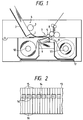
- Fig. 1 is a diagram showing an embodiment of a thermal transfer image forming apparatus the invention, which includes a thermal transfer print mechanism and a controller.
- the thermal transfer print mechanism includes a sheet feed mechanism 4 for conveying a single recording sheet by drawing out the sheet from a stacker 2 with a pickup roller 3, a platen 5 for forwarding the recording sheet 1 and an ink sheet 9 at a predetermined speed, a print mechanism 7 formed of a thermal transfer printhead 6 which is in continual pressure contact with the platen 5 during printing, a forward roller 8 for returning the printed recording sheet to the stacker 2, a stock roller 10 for supplying the ink ribbon 9, and a rewind roller 11.
- On the bottom of the housing is disposed a circuit board 12 into which a control circuit (to be described later) is assembled.
- the thermal transfer printhead 6 is constructed so that heating resistor elements 14 are arranged at a predetermined pitch in a row on a surface of a substrate 13 and leads 15, 16 are drawn out in a sheet forwarding direction.
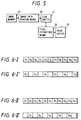
- Fig. 3 shows an embodiment of the control circuit.
- reference numeral 17 designates a microcomputer which forms the heart of the controller.
- the microcomputer 17 includes a CPU (central processing unit) 18, a ROM (read only memory) 19 in which control programs and data processing programs (described later) are stored, and a RAM (random access memory) 20 forming data processing buffers and frame memories.
- the microcomputer 17 is connected to external devices including a personal computer, a printhead drive circuit 23 and a motor drive circuit 24, through interfaces 21, 22.
- the printhead drive circuit 23 is arranged so that each of the heating resistor elements 14 of the thermal transfer printhead 6 is supplied with electric energy corresponding to density data outputted from the interface 22, the electric energy being, for example, pulsed power at times T1, T2, T3, T4, ⁇ , T n sequentially increased in accordance with density B1, B2, B3, B4, ⁇ , B n , as shown in Fig. 4.
- the motor drive circuit 24 outputs a drive pulse to a motor so that the motor can rotate in such a direction and at such a speed as to correspond to an instruction delivered from the interface 22.
- FIG. 5 schematically shows the functions implemented by the microcomputer 17.
- An image memory 25 stores single-page-long input data.
- An image data reading unit 26 extracts single-line-long data of a predetermined color and stores the extracted data in a line buffer 27.
- a pixel extracting circuit 28 extracts every second image data from the image data stored in the line buffer 27 in the main scanning direction and outputs the extracted data to a print buffer 29.
- the microcomputer 17 When image data is inputted from an external device such as a personal computer, the microcomputer 17 stores single-page-long image data in the image memory 25, and extracts print data of a first color, e.g ., cyan data, among single line-long image data to be printed, and outputs such extracted print data to the line buffer 27.
- image data D1, D2, D3, D4, D5, ⁇ , D10, D11, D12 (Fig. 6-I) have been stored in the line buffer 27, the image data are extracted alternately in the main scanning direction. For example, the image data D1, D3, D5, ⁇ , D11 (Fig. 6-II) representing odd pixel data are applied to the print buffer 29.
- the microcomputer 17 outputs density data specific to each of the image data stored in the print buffer 29 to the thermal transfer printhead drive circuit 23 through the interface 22.
- the thermal transfer printhead drive circuit 23 supplies alternate heating resistor elements 14, e.g ., odd ones, with electric energy specified by the density data. In supplying the electric energy, the applied electric energy is proportional to the reciprocal of an extracting rate, and excluded pixel data is added to another pixel data which neighbors such excluded pixel data and which is to be printed.
- the odd heating resistor elements 14 to be driven are free from thermal interference with other neighboring heating resistor elements. Therefore, they accurately transfer areas of ink proportional to the supplied electric energy, and the average density over the entire print surface is consistent with the image data.
- the heating resistor element 14 is heated so as to form a circular isothermal line with its center being at the highest temperature, since the region in an ink sheet that is heated to an ink melting temperature by the supplied electric energy has a higher degree of heat dissipation at its outer periphery as long as its relative input energy is small due to its periphery being in contact with the environment.
- the heated area of the heating resistor element 14 becomes larger than that of the heating resistor element 14, expanding to the neighboring heating resistor elements.
- the ink melted area is proportional to the magnitude of electric energy E1, E2, E3, E4, E5, ⁇ , as shown in Fig. 7(a). That is, a dot is formed by expanding the ink melted area in proportion to the relative input energy, even with respect to relative input energy E32 which exceeds conventionally used relative input energy E12, as shown in Fig. 8.
- the upper limit of reproducible maximum density is increased, so that the number of tones is increased to allow the density specified by the image data to be accurately expressed, thereby achieving dot formation with tones permitting full-color printing.
- the microcomputer 17 When the single line-long data has been printed, the microcomputer 17 outputs a signal equivalent to a single-line spacing to the motor drive circuit 24 and rotates the forward roller 8 to forward both the recording sheet I and the ink sheet by the single line spacing. Accordingly, a new portion of the ink sheet and a nonprinted portion of the recording sheet are provided in the print region on the printhead 6.
- the image data reading unit 26 causes data corresponding to a next single line D1, D2, D3, D4, D5, ⁇ , D10, D11, D12 to be stored in the buffer from the image memory 25, while the digits that have not been printed in the last printing, i.e . , only the even image data D2, D4, ⁇ D10, D12, are extracted and stored in the print buffer 29.
- the same process as the first line printing process is performed to print a third line. Since the heating resistor elements to be used in the third line printing have been turned off during the last printing process, they are capable of heating an area that is accurately proportional to the supplied electric energy. Thus, data is processed alternately between the odd and even digits on a line-by-line basis so that the areas indicated by hatching in Fig. 9 are printed as dots.
- dots formed by the conventional apparatus become sporadically contiguous if such relative input energy as to not saturate is supplied (Fig. 10(b)-I), and almost all the dots become contiguous when relative input energy that is only one-third the energy required for the apparatus of the invention to form the largest dot has been supplied (Fig. 10(b)-II).
- the microcomputer 17 causes the printhead 6 to be separated from the platen 5 to form a gap therebetween, causes the forward roller 8 to rotate in reverse to reset a recording sheet at a print start position, and further causes the ink sheet rewind roller 11 to rotate to position a second color ink region at the printhead. Thereafter, printing for the second color is performed, following the same process as the printing process for the first color.
- Fig. 12 is a diagram showing a second embodiment by way of functions performed by the microcomputer.
- reference numeral 31 designates an image data reading unit, which not only extracts N line(s) (N is an integer greater than 1) from single page-long image data stored in an image memory 30 while moving two line-long image data every N line(s) in this embodiment, but also outputs the extracted data to a line buffer 32.
- Reference numeral 33 designates a sampling circuit, which samples N-digit-long image data (N is an integer greater than 1) in the main scanning direction from the image data stored in the line buffer 32 ( i.e ., N ⁇ N dots, or regions S1, S2, S3, S4, ⁇ , each consisting of 2 ⁇ 2 pixels) and outputs the extracted data to a pixel extracting circuit 34.
- the pixel extracting circuit 34 compares each of the pixels L1, L2, L3, L4 of a sampling region stored in an evaluation data storage unit 35 (Fig. 13 and Fig. 14(a)) with data stored in the evaluation data storage unit 35 (Fig.
- each of the data being set as a threshold, such as, for example, "0”, the lowest density a 1 for the pixel L11, "11”, the highest density a 2 for the pixel L2 which is adjacent to the pixel L11 "10”, the second highest density a 3 for the pixel L3 which is located immediately below the lowest density, and "2", the second lowest density a 4 for the pixel L4 which is obliquely below and independent from the pixel L1 contributing to forming a dot, and outputs only the image data exceeding the threshold(s) to a print buffer 36.
- a threshold such as, for example, "0”, the lowest density a 1 for the pixel L11, "11”, the highest density a 2 for the pixel L2 which is adjacent to the pixel L11 "10”, the second highest density a 3 for the pixel L3 which is located immediately below the lowest density, and "2”, the second lowest density a 4 for the pixel L4 which is obliquely below and independent from the pixel L1 contributing
- the image data reading unit 31 reads the first two lines of data and stores the read data in the line buffer 32.
- 2 ⁇ 2 image data D11, D12, D21, D22 in the first sampling region S1 are compared with the thresholds in the evaluation data storage unit 35. For example, if image data having such tones as shown in Fig. 15 are outputted, only the image data D11 exceeding the corresponding threshold is delivered to the print buffer 36 with respect to the sampling region S1.
- the sampling circuit 33 reads image data D13, D14, D23, D24, from the next sampling region S2 and compares them with the thresholds stored in the evaluation data storage unit 35.
- the density values of the image data D13, D24 exceed the thresholds, only the image data D13, D24 are applied to the print buffer 36. While sequentially moving the sampling regions, only the image data exceeding the thresholds are outputted to the print buffer 36. As a result, one of the neighboring dots is excluded from the data present on the same line as shown in Fig. 16, thus extracting only the pixels D11, D13, D15, D17, D19 as well as substantially alternate pixels D24, D25, D26, D28.
- the microcomputer 17 Upon completion of extracting the print data from the two line-long image data, the microcomputer 17 feeds the image data stored in the print buffer 36 to the printhead drive circuit 23 through the interface 22. Accordingly, since alternate heating resistor elements of the printhead 6 are driven with respect to the first line as described previously, the heating resistor elements contributing to forming dots can express the tones satisfactorily even for high density image data as described above.
- the microcomputer 17 Upon completion of printing the first line in this manner, the microcomputer 17 forwards the recording sheet 1 and the ink sheet 9 a single line while driving the pulse motor, and then similarly prints the second line data from the print buffer 36.
- the next two lines of data e.g ., the third and fourth lines
- the image memory 30 similarly sampled on a 2 ⁇ 2 pixel basis, and compared with the thresholds, and only the image data exceeding the corresponding threshold(s) are supplied to the print buffer 36 and then printed.
- image data to be excluded can be determined in accordance with the density of the image data.
- image data to be excluded can be determined in accordance with the density of the image data.
- the thresholds which are the evaluation data
- the pixel density can be modified to, for example, 1/2, by setting two of the thresholds to, for example, "11,” which is a value allowing the highest density to be extracted, and, for example, 1/4, by setting three of the thresholds to "11.”
- suitable printing conditions can be set in accordance with the original image data and the quality of a recording sheet by variously changing the evaluation data for intermediate density thresholds.
- Fig. 17 is a diagram showing a third embodiment indicated by way of functions performed by the microcomputer.
- reference numeral 41 designates an image data reading unit, which extracts N line(s) (N is an integer greater than 1) from single-page-long image data stored in an image memory 40 while moving two-line-long image data every N line(s) in this embodiment, and outputs the extracted data to a line buffer 42.
- Reference numeral 43 designates a sampling circuit which samples N-digit-long image data (N is an integer greater than 1) in the main scanning direction from the image data stored in the line buffer 42, ( i.e ., N ⁇ N dots, or regions S1, S2, S3, S4, each consisting of 2 ⁇ 2 pixels) and outputs the extracted data to a tone determining unit 44.
- the tone determining unit 44 compares each of the pixels L1, L2, L3, L4 of a sampling region stored in an evaluation data storage unit 45 (Fig. 14(a)) with data stored in the evaluation data storage unit 45 (Fig.
- each of the data being set as a threshold, such as "0" the lowest density a 1 for the pixel L1, "11” the highest density a 2 for the pixel L2 which is adjacent to the pixel L1, "10” the second highest density a 3 for the pixel L3 which is located immediately below the lowest density, and "2" the second lowest density a 4 for the pixel L4 which is obliquely below and independent from the pixel L1 contributing to forming a dot, and extracts only the image data exceeding the corresponding threshold(s), adds the tone(s) of the data equal to or below the threshold(s) to the data exceeding the threshold(s), and outputs the sum to a print buffer 46.
- a threshold such as "0" the lowest density a 1 for the pixel L1, "11” the highest density a 2 for the pixel L2 which is adjacent to the pixel L1, "10” the second highest density a 3 for the pixel L3 which is located immediately below the lowest density, and “2" the second lowest density
- the image data reading unit 41 reads the first two lines of data and stores the read data in the line buffer 42.
- 2 ⁇ 2 image data D11, D12, D21, D22 in the first sampling region S1 are compared with the thresholds in the evaluation data storage unit 45. For example, if image data having such tones as shown in Fig.
- the sampling circuit 43 reads data D13, D14, D23, D24 from a next sampling region S2, and similarly compares them with the thresholds stored in the evaluation data storage unit.
- the density values of the data D13, D24 exceed the corresponding thresholds, the density values "11,” “9” of the pixels D14, D23 which are equal to or below the corresponding thresholds are added to the density values "12", "3" of the pixels D13, D24, in order not to produce error of the density value in the 2 X 2 matrix area of the pixels D13, D14, D23 and D24. Consequently, the density value of D13 and D24 is corrected to the value of "22" and "13", respectively, and the corrected data are applied to the print buffer 46.
- the sampling unit 43 reads the data D15, D16, D25, D26 from the next sampling region S3 and compares the read data with the thresholds in the evaluation data storage unit 45 in accordance with the same process.
- the density value "6" of the pixel D16 which is smaller than the threshold is added to the density data "2," "11,” and “7” of the density data of the pixels D15, D25, D26, and the density values are so corrected as to be a density "4" for the data D15, a density "13” for the data D25, and a density “9” for the data D26, and the corrected density data are outputted to the print buffer 46.
- the density data of the data equal to or less than the threshold(s) are added to those of the image data exceeding the threshold(s) and outputted to the print buffer 46.
- one of the neighboring dots are excluded from the data present on the same line as shown in Fig. 18, thus extracting only the pixel D11, D13, D15, D17, D19, as well as substantially alternate pixels D24, D25, D26, D28.
- the microcomputer 17 Upon completion of extracting the print data from the two line-long image data, the microcomputer 17 feeds the image data stored in the print buffer 36 to the printhead drive circuit 23 through the interface 22. Accordingly, since alternate heating resistor elements of the printhead 6 are driven with respect to the first line as described previously, the heating resistor elements contributing to forming dots can reproduce the density of even a high density image data accurately as described above, thus permitting a satisfactory overall tone representation.
- the microcomputer 17 Upon completion of printing the first line in this manner, the microcomputer 17 forwards the recording sheet 1 and the ink sheet 9 a single line while driving the pulse motor, and then similarly prints the second line data from the print buffer 46.
- the next two lines of data for example, the third and fourth lines, are read from the image memory 40, similarly sampled on a 2 ⁇ 2 pixel basis, and compared with the thresholds, and only the image data exceeding the corresponding threshold(s) are supplied to the print buffer 46 and then printed.
- This embodiment not only determines pixel(s) to be excluded in accordance with the density of the pixels forming a portion of the image data, but also reflects the density of the pixel(s) to be excluded upon the density of the pixels to be printed, so that high density dots can be formed under satisfactory tone expression. In addition, by preventing neighboring high density pixels from being omitted, this embodiment allows printing to be more representative of the input image data.
- the density of image data not contributing to forming a dot is uniformly distributed to the density of image data contributing to forming a dot in this embodiment, it may be so arranged that the density data are distributed in inverse proportion to the evaluation data thresholds.
- multiplication of the extracted data substantially by the reciprocal of an extracting rate every matrix or every line contributes to preventing a density reduction in the entire image attributable to image data exclusion.
- Fig. 19 shows an embodiment in which the tone determining unit 44 and the evaluation data storage unit 45 in the third embodiment are replaced with a ⁇ conversion unit.
- the process of sampling the image data to be evaluated by image memory 40, the image data reading unit 41, the line buffer 42, and the sampling circuit 43 is the same as described above.
- the ⁇ conversion unit 47 determines a single conversion characteristic with respect to the position of dot data within a sampled region, in such a manner that sampled data, e.g .
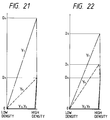
- Fig. 21 shows an exemplary ⁇ characteristic set in the conversion unit 47.
- the conversion characteristic function ⁇ 1 has a conversion characteristic in which an image data value is changed so as to be substantially linear with conversion print data Db corresponding to sufficiently high electric energy as a maximum, and in which, if the image data value is the maximum allowed by the heating resistor element, the image data is converted into print data D a that is the same as the image data value.
- the conversion characteristic function ⁇ 4 has a substantially linear conversion characteristic with D a as a maximum.
- each of the conversion characteristic functions ⁇ 2 and ⁇ 3 has a characteristic in which, when an image data value has the highest density value, the conversion print data D a which is substantially the same as the image data value is outputted, and in which, when it is lower than the highest density value, conversion print data which is substantially zero is outputted.
- the image data D11 in the sampled region S1 in this embodiment is converted into conversion print data that is linearly proportional to the image data D11 by the conversion characteristic function ⁇ 1 of the ⁇ conversion unit 47, while the image data D12 is converted into conversion print data resulting in a density D a only if the density assumes the highest value, otherwise it is converted into conversion print data resulting in a density of substantially zero by the conversion characteristic function ⁇ 2. Further, the image data D21 is converted into conversion print data resulting in density D a only if the density assumes the highest value in the same manner as the image data D12, and otherwise it is converted into conversion print data resulting in a density of substantially zero.
- the image data D22 is converted into a substantially linearly proportional conversion print data so that its highest density becomes D a . As a result, the image data D12 , D22 are virtually excluded.
- the microcomputer 17 When the two line-long image data have been converted into print data, the microcomputer 17 outputs the print data stored in the print buffer 46 to the printhead drive circuit 23 through the interface 22. Accordingly, as described above, alternate heating resistor elements of the printhead 6 are operated with the conversion output indicated by the conversion characteristic function ⁇ 1 with respect to the first line. As a result, the density corresponding to each image data can be reproduced accurately while receiving sufficiently high electric energy even for high density dot data. Further, image data of the highest density are converted into conversion print data D a by the conversion characteristic functions ⁇ 1 and ⁇ 4, and into conversion print data D a by the conversion characteristic functions ⁇ 2 and ⁇ 3, thereby forming contiguous dots and reproducing the pattern with high density and high resolution.
- the microcomputer 17 drives the pulse motor to forward the recording sheet 1 and the ink sheet 9 a single line, and then delivers second line data stored in the print buffer 46 to the printhead drive circuit 23 to start printing.
- the conversion characteristic function ⁇ 3 is set to the image data D21 in the sampled region S1, such data is virtually excluded unless its density is the highest value.
- the image data D22 is set to the conversion characteristic function ⁇ 4, it is printed at a density that is proportional to the electric energy thereby supplied. Accordingly, the dot D22 printed in the second line is printed at a position shifted obliquely with respect to the dot D11 printed in the first line.
- the heating resistor element corresponding to the image data D22 can be driven to its full capacity to form the dot. Further, for an extremely high density image region (e.g ., all the dots in the sampling region S are of the highest density) all the sampled image data are to be printed, so that the conversion print data D a is outputted to allow their tones and average density to be accurately reproduced.
- an extremely high density image region e.g ., all the dots in the sampling region S are of the highest density
- the next two lines of data i.e ., the image data of the third and fourth lines
- the image memory 40 Upon completion of printing the two lines, the next two lines of data (i.e ., the image data of the third and fourth lines) are read from the image memory 40, subjected to a ⁇ conversion process after sampling them on a 2 ⁇ 2 pixel basis as described previously, and applied to the print buffer 46, and printing is performed thereafter.
- the conversion characteristic function ⁇ 1 since the conversion characteristic function ⁇ 1 becomes prevalent in the majority of regions with the conversion characteristic function ⁇ 4 serving as an auxiliary, many of the pixels of the average image data assumes the characteristic given by the conversion characteristic function ⁇ 1 among dots in the 2 ⁇ 2 sampling regions, thus making the number of pixels to be substantially 1/2 to 2/4. It is noted that, as described above, the conversion characteristic function ⁇ 1 supplies electric energy about three times the normal driving energy to the heating resistor elements, thereby allowing the ink on the ink ribbon to be melted surely and providing the advantage that it is hard to be affected by variations in conditions such as the quality of recording sheets. Further, since there are many image data such as characters which demand high resolution printing for the highest density portion, it is arranged so that all the pixels in a 2 ⁇ 2 sampling region are printed at the density D a that is the same as the image data.
- Fig. 22 shows an embodiment in which the highest conversion print data is set to D d , having a density which is lower than in the previous embodiment, for the conversion characteristic function ⁇ 1, and the supplied electric energy is set to D c , which is higher than D a , for the maximum conversion print data for the conversion characteristic function ⁇ 4.
- the pixels are formed by the conversion characteristic functions ⁇ 1, and ⁇ 4 in the majority of the regions, thereby allowing higher resolution printing to be performed than in the previous embodiments.
- a ⁇ conversion characteristic shown in Fig. 23 decreases the highest conversion print data to De, which is lower than in the above embodiment, while the conversion characteristic functions ⁇ 1 and ⁇ 4 are characterized to provide the dot size at the same rate and the conversion characteristic functions ⁇ 2 and ⁇ 3 are characterized so as to output the conversion print data D a only when the image data indicates the highest value. Therefore, according to this embodiment, dots are formed by the conversion characteristic functions ⁇ 1 and ⁇ 4 in the majority of the regions, resulting in about half of the image data being subjected to printing. Thus, with the use of recording sheets having excellent transfer characteristics, the resolution can further be improved.
- a ⁇ conversion characteristic indicated in Fig. 24 prints only the conversion characteristic function ⁇ 1 which is set to conversion print data D f ( i.e ., one pixel out of the 2 ⁇ 2 pixels in a sampling region with a steep rise). If image data whose density is higher than the above is inputted, then the printing is performed, taking into consideration the conversion characteristic function ⁇ 4 in which the highest dot size D h is set. According to this embodiment, since the characteristic with which a large dot size compared to the density of image data in the low density region is set by the conversion characteristic function ⁇ 1, stable transfer characteristics can be exhibited.
- a conversion characteristic function ⁇ indicated in Fig. 25 prints only one dot when the density of image data is low. However, since the proportional coefficients of the image data and the conversion print data in the low density region are set to values smaller than the ⁇ conversion characteristic shown in Fig. 24, the tone characteristic in the low and high density regions are improved, while the tone characteristic is accurate with respect to the density of the image in half tone regions.
- Fig. 26 shows another exemplary conversion characteristic function ⁇ set in the ⁇ conversion unit 47.
- the conversion characteristic function ⁇ 1 exhibits such a substantially linear characteristic as to provide a minimum conversion print data D k which is so small that no dot is transferred at an initial stage with respect to an image data value, and a maximum conversion print data D h that is sufficiently high supplied electric energy with respect to image data in the medium density region, with the conversion print data D h being maintained at a region between the medium density region and the high density region, so that conversion print data D i that is close to the image data can be obtained at the highest density region.
- the conversion characteristic function ⁇ 2 has such a characteristic as not only to provide the conversion print data D k that is so small as to not form a transfer dot in almost all the regions, but also to provide conversion print data D j which is close to the image data in the vicinity of the highest density value.
- the conversion characteristic function ⁇ 3 exhibits such a characteristic as not only to provide the conversion print data D k that is so small as to not form a transfer dot in almost all the regions that the conversion characteristic function ⁇ 2 does, but also to provide the conversion print data D j that is close to the image data or data approximated to D j in the highest density region as well as in its vicinity.
- the conversion characteristic function ⁇ 4 has such a substantially linear characteristic so as to provide a minimum conversion print data D k which does not form a transfer dot in the low density region of the image data at an initial stage.
- the density of the image data rises steeply to the conversion print data D j which can form a sufficient transfer dot and maintains such a value to the medium density region thereafter.
- the highest print data D h is provided over a range between the medium density region and the high density region, and a conversion print data D i is provided that is close to the density of the image data in the highest density region.
- sufficiently high electric energy is supplied to the image data by the conversion characteristic function ⁇ 4 at the initial stage of printing, thereby allowing a relatively large, stable transfer dot to be formed, and transfer dots to be formed by the conversion characteristic function ⁇ 1 over the medium region allow the density to increase gradually.
- the density of the transfer dots is further gradually increased toward the high density region by the conversion characteristic function ⁇ 4. In the vicinity of the highest density region, the density is increased in combination with dots formed by the conversion characteristic function ⁇ 3.
- the conversion print data D i derived from the conversion characteristic functions ⁇ 1 and ⁇ 4 is added, while the conversion data D j derived from the conversion characteristic functions ⁇ 2 and ⁇ 3 are added to form transfer dots. Accordingly, the transfer dots can be formed stably at all times in all the regions.
- the tone expression in the medium density region can selectively be improved.
- the best print result can be obtained by selecting the ⁇ characteristic in accordance with the object to be printed. That is, if emphasis is given to higher tones, one conversion characteristic function ⁇ 1 may be set so that a steep characteristic is provided and another conversion characteristic function ⁇ 4 may be set so that a smaller slope is provided. If emphasis is given to high resolution, the conversion characteristic function ⁇ 4 may be arranged close to the conversion characteristic function ⁇ 1, or the conversion characteristic function ⁇ 2 or ⁇ 3 may be set to exhibit a smooth characteristic.
- the best tone characteristic can be obtained by appropriately selecting the magnitude of a maximum and a minimum as well as the slope to be set to the conversion print data in accordance with the image to be printed or with the type of a sheet serving as a print medium.
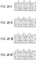
- the conversion characteristic functions ⁇ 1, ⁇ 2, ⁇ 3, ⁇ 4 are distributed differently on a color basis to a plurality of print data D nm , which are sampled as print data, as shown in Figs. 28-I, 28-II, 28-III, and 28-IV. More specifically, a distribution of the conversion characteristic functions ⁇ 1, ⁇ 2, ⁇ 3, ⁇ 4 as shown in Fig. 28-I for yellow, a distribution of the conversion characteristic functions ⁇ 1, ⁇ 2, ⁇ 3, ⁇ 4 as shown in Fig.
- N-digit-long data (N is an integer greater than 1) are sampled in the main scanning direction from the image data stored in the line buffer 32 ( i.e ., N ⁇ N dots, or the regions S1, S2, S3, S4, each consisting of 2 ⁇ 2 pixels) then the data position to which each conversion characteristic is assigned is differentiated per ink color, in such a manner that, with respect to the data D11, D12, S21, S22 forming the region S1, for yellow, the conversion characteristic function ⁇ 1 is set to the data D11, the conversion characteristic function ⁇ 2 to the data D12, the conversion characteristic function ⁇ 3 to the data D21, the conversion characteristic function ⁇ 4 to the data D22, for magenta, the conversion characteristic function ⁇ 3 is set to the data D11, the conversion characteristic function ⁇ 1 to the data D12, the conversion characteristic function ⁇ 4 to the data D21, and the conversion characteristic function ⁇ 2 to the data D22, and so on. Accordingly, overlapping of dots formed by different color inks
- sampling region is set to 2 ⁇ 2 dots.
- the invention provides a printhead having a plurality of heating resistor elements arranged in a row, means for forwarding a recording sheet and an ink sheet at a predetermined pitch; means for extracting image data forming inputted image data at a certain interval, and means for supplying the heating resistor elements of the printhead with electric energy corresponding to a density specified by the image data so as to correspond to the extracting interval. Therefore, the image data is extracted at an interval amounting at least to a single pixel out of the image data fed from an external device in the main scanning direction so as to prevent thermal interference with the neighboring heating resistor elements.
- the heating resistor elements are operated accurately by with respect to such electric energy as to form a dot larger than the dot size specified by the highest density of the inputted image data.
- density can be expressed in more gradations than with the conventional apparatus. This permits sufficient tone expression and color reproduction even if the area of a sampling region is reduced, hence reducing the dither processing steps to thereby decrease image data processing time and preventing generation of texture noise.
Landscapes
- Engineering & Computer Science (AREA)
- Multimedia (AREA)
- Signal Processing (AREA)
- Electronic Switches (AREA)
Applications Claiming Priority (2)
| Application Number | Priority Date | Filing Date | Title |
|---|---|---|---|
| JP55912/91 | 1991-02-27 | ||
| JP5591291A JPH04212868A (ja) | 1990-11-22 | 1991-02-27 | 熱転写式画像形成装置 |
Publications (2)
| Publication Number | Publication Date |
|---|---|
| EP0501487A2 true EP0501487A2 (fr) | 1992-09-02 |
| EP0501487A3 EP0501487A3 (en) | 1992-12-09 |
Family
ID=13012330
Family Applications (1)
| Application Number | Title | Priority Date | Filing Date |
|---|---|---|---|
| EP19920103382 Withdrawn EP0501487A3 (en) | 1991-02-27 | 1992-02-27 | Thermal transfer image forming apparatus |
Country Status (2)
| Country | Link |
|---|---|
| EP (1) | EP0501487A3 (fr) |
| SG (1) | SG48857A1 (fr) |
Cited By (2)
| Publication number | Priority date | Publication date | Assignee | Title |
|---|---|---|---|---|
| US7446788B2 (en) * | 2001-03-01 | 2008-11-04 | Zipher Limited | Printing |
| WO2019220079A1 (fr) * | 2018-05-15 | 2019-11-21 | Global Inkjet Systems Limited | Procédé d'impression à jet d'encre |
Family Cites Families (4)
| Publication number | Priority date | Publication date | Assignee | Title |
|---|---|---|---|---|
| JPS58158277A (ja) * | 1982-03-16 | 1983-09-20 | Victor Co Of Japan Ltd | 熱転写型印刷装置 |
| US4635078A (en) * | 1983-04-28 | 1987-01-06 | Canon Kabushiki Kaisha | Intermediate gradient image producing method |
| JPH0630887B2 (ja) * | 1984-10-17 | 1994-04-27 | 株式会社リコー | サーマルプリンタ |
| JPS6288476A (ja) * | 1985-10-15 | 1987-04-22 | Seiko Instr & Electronics Ltd | 画像プリンタ |
-
1992
- 1992-02-27 EP EP19920103382 patent/EP0501487A3/en not_active Withdrawn
- 1992-02-27 SG SG1996003113A patent/SG48857A1/en unknown
Cited By (5)
| Publication number | Priority date | Publication date | Assignee | Title |
|---|---|---|---|---|
| US7446788B2 (en) * | 2001-03-01 | 2008-11-04 | Zipher Limited | Printing |
| US8330780B2 (en) | 2001-03-01 | 2012-12-11 | Videojet Technologies (Nottingham) Limited | Printing |
| US8687033B2 (en) | 2001-03-01 | 2014-04-01 | Videojet Technologies (Nottingham) Limited | Printing |
| WO2019220079A1 (fr) * | 2018-05-15 | 2019-11-21 | Global Inkjet Systems Limited | Procédé d'impression à jet d'encre |
| US11529804B2 (en) | 2018-05-15 | 2022-12-20 | Global Inkjet Systems Limited | Inkjet printing method |
Also Published As
| Publication number | Publication date |
|---|---|
| SG48857A1 (en) | 1998-05-18 |
| EP0501487A3 (en) | 1992-12-09 |
Similar Documents
| Publication | Publication Date | Title |
|---|---|---|
| US4686538A (en) | Tone recording method | |
| JPS60240277A (ja) | 中間調記録方法 | |
| US5091734A (en) | Color image recording utilizing color correction in accordance with a predetermined order of recording of multiple color agents | |
| EP0660586A2 (fr) | Procédé pour la commande de gradation et amélioration de la qualité de l'image dans une imprimante thermique | |
| EP0501487A2 (fr) | Appareil de restitution d'images par transfert thermique | |
| EP0452928B1 (fr) | Appareil d'enregistrement d'images à gradations multiples | |
| EP0248616A2 (fr) | Appareil imprimeur d'image | |
| US5359424A (en) | Thermal transfer image forming apparatus using different gamma functions for different density ranges | |
| JP3152799B2 (ja) | 熱記録方法 | |
| US4984092A (en) | Halftone image gradation data converted to bit-train data with data retained after thresholding converted to pulse-train data | |
| JPH0720199B2 (ja) | 画像処理装置 | |
| US5734410A (en) | Thermal transfer recording apparatus and method for regularly assigning blank dots | |
| JP2943408B2 (ja) | 熱転写式画像形成装置 | |
| JP2946864B2 (ja) | 熱転写式画像形成装置 | |
| JP3094540B2 (ja) | 熱転写式画像形成装置 | |
| JP3094539B2 (ja) | 熱転写式画像形成装置 | |
| JP3489288B2 (ja) | 画像処理方法および画像処理装置 | |
| JP3333596B2 (ja) | 熱転写式記録装置 | |
| JP2638041B2 (ja) | プリンタ装置 | |
| JPS60141585A (ja) | カラ−画像形成方法 | |
| JPS6084071A (ja) | 画像記録装置 | |
| JP2994855B2 (ja) | 多階調熱記録方法 | |
| JPH04212868A (ja) | 熱転写式画像形成装置 | |
| JPH05261962A (ja) | 熱転写式画像形成装置 | |
| JPH05220996A (ja) | 画像記録方法および装置 |
Legal Events
| Date | Code | Title | Description |
|---|---|---|---|
| PUAI | Public reference made under article 153(3) epc to a published international application that has entered the european phase |
Free format text: ORIGINAL CODE: 0009012 |
|
| AK | Designated contracting states |
Kind code of ref document: A2 Designated state(s): DE FR GB |
|
| PUAL | Search report despatched |
Free format text: ORIGINAL CODE: 0009013 |
|
| AK | Designated contracting states |
Kind code of ref document: A3 Designated state(s): DE FR GB |
|
| 17P | Request for examination filed |
Effective date: 19930309 |
|
| 17Q | First examination report despatched |
Effective date: 19951201 |
|
| APAB | Appeal dossier modified |
Free format text: ORIGINAL CODE: EPIDOS NOAPE |
|
| APAB | Appeal dossier modified |
Free format text: ORIGINAL CODE: EPIDOS NOAPE |
|
| APAD | Appeal reference recorded |
Free format text: ORIGINAL CODE: EPIDOS REFNE |
|
| APCB | Communication from the board of appeal sent |
Free format text: ORIGINAL CODE: EPIDOS OBAPE |
|
| APAB | Appeal dossier modified |
Free format text: ORIGINAL CODE: EPIDOS NOAPE |
|
| STAA | Information on the status of an ep patent application or granted ep patent |
Free format text: STATUS: THE APPLICATION IS DEEMED TO BE WITHDRAWN |
|
| 18D | Application deemed to be withdrawn |
Effective date: 19991128 |
|
| APAF | Appeal reference modified |
Free format text: ORIGINAL CODE: EPIDOSCREFNE |