EP0501496A2 - Bildverarbeitungsgerät - Google Patents
Bildverarbeitungsgerät Download PDFInfo
- Publication number
- EP0501496A2 EP0501496A2 EP92103402A EP92103402A EP0501496A2 EP 0501496 A2 EP0501496 A2 EP 0501496A2 EP 92103402 A EP92103402 A EP 92103402A EP 92103402 A EP92103402 A EP 92103402A EP 0501496 A2 EP0501496 A2 EP 0501496A2
- Authority
- EP
- European Patent Office
- Prior art keywords
- power
- supply
- switch
- microcomputer
- time
- Prior art date
- Legal status (The legal status is an assumption and is not a legal conclusion. Google has not performed a legal analysis and makes no representation as to the accuracy of the status listed.)
- Granted
Links
Images


Classifications
-
- G—PHYSICS
- G03—PHOTOGRAPHY; CINEMATOGRAPHY; ANALOGOUS TECHNIQUES USING WAVES OTHER THAN OPTICAL WAVES; ELECTROGRAPHY; HOLOGRAPHY
- G03G—ELECTROGRAPHY; ELECTROPHOTOGRAPHY; MAGNETOGRAPHY
- G03G15/00—Apparatus for electrographic processes using a charge pattern
- G03G15/50—Machine control of apparatus for electrographic processes using a charge pattern, e.g. regulating differents parts of the machine, multimode copiers, microprocessor control
- G03G15/5004—Power supply control, e.g. power-saving mode, automatic power turn-off
-
- G—PHYSICS
- G03—PHOTOGRAPHY; CINEMATOGRAPHY; ANALOGOUS TECHNIQUES USING WAVES OTHER THAN OPTICAL WAVES; ELECTROGRAPHY; HOLOGRAPHY
- G03G—ELECTROGRAPHY; ELECTROPHOTOGRAPHY; MAGNETOGRAPHY
- G03G15/00—Apparatus for electrographic processes using a charge pattern
- G03G15/80—Details relating to power supplies, circuits boards, electrical connections
-
- H—ELECTRICITY
- H02—GENERATION; CONVERSION OR DISTRIBUTION OF ELECTRIC POWER
- H02M—APPARATUS FOR CONVERSION BETWEEN AC AND AC, BETWEEN AC AND DC, OR BETWEEN DC AND DC, AND FOR USE WITH MAINS OR SIMILAR POWER SUPPLY SYSTEMS; CONVERSION OF DC OR AC INPUT POWER INTO SURGE OUTPUT POWER; CONTROL OR REGULATION THEREOF
- H02M3/00—Conversion of DC power input into DC power output
- H02M3/22—Conversion of DC power input into DC power output with intermediate conversion into AC
- H02M3/24—Conversion of DC power input into DC power output with intermediate conversion into AC by static converters
- H02M3/28—Conversion of DC power input into DC power output with intermediate conversion into AC by static converters using discharge tubes with control electrode or semiconductor devices with control electrode to produce the intermediate AC
- H02M3/325—Conversion of DC power input into DC power output with intermediate conversion into AC by static converters using discharge tubes with control electrode or semiconductor devices with control electrode to produce the intermediate AC using devices of a triode or a transistor type requiring continuous application of a control signal
- H02M3/335—Conversion of DC power input into DC power output with intermediate conversion into AC by static converters using discharge tubes with control electrode or semiconductor devices with control electrode to produce the intermediate AC using devices of a triode or a transistor type requiring continuous application of a control signal using semiconductor devices only
- H02M3/33507—Conversion of DC power input into DC power output with intermediate conversion into AC by static converters using discharge tubes with control electrode or semiconductor devices with control electrode to produce the intermediate AC using devices of a triode or a transistor type requiring continuous application of a control signal using semiconductor devices only with automatic control of the output voltage or current, e.g. flyback converters
- H02M3/33515—Conversion of DC power input into DC power output with intermediate conversion into AC by static converters using discharge tubes with control electrode or semiconductor devices with control electrode to produce the intermediate AC using devices of a triode or a transistor type requiring continuous application of a control signal using semiconductor devices only with automatic control of the output voltage or current, e.g. flyback converters with digital control
Definitions
- This invention relates to an image processing apparatus in which the supply of electric power to portions other than an electronic control system is capable of being turned on and off by control performed by the electronic control system.
- Various apparatus such as copying machines are provided with an automatic shut-off mechanism for turning off the apparatus automatically in a case where the apparatus is not used for a certain period of time or a case where some abnormality is detected.
- the purpose of such a mechanism is conserve energy and enhance safety.
- these conventional automatic shut-off mechanisms employ a switch of the type in which a solenoid is provided within a see-saw switch, wherein the see-saw switch is opened and closed mechanically depending upon whether the solenoid is energized or not.
- the switch is such that on/off control is made possible from the apparatus side.
- the switch makes it possible for the user of the apparatus to turn the power supply on and off directly by a manual operation.
- the switch in an arrangement of this kind is high in price and makes it difficult to achieve an apparatus which is compact and low in cost.
- a switch of this kind possesses a complicated structure and is not satisfactory in terms of reliability and durability.
- the only component not supplied with power is the fixing heater or the display one the display/control panel; power continues to be supplied to the other components of the apparatus. Consequently, there is the possibility that the components being supplied with power will malfunction during this time. This is undesirable in terms of safety at the time of a malfunction.
- An object of the present invention is to provide an image processing apparatus in which, when the apparatus has not been used for a prescribed period of time, control is performed so as to halt feed of current not only to a display unit and fixing heater but also to other components not required to operate when the apparatus is not in use, and in which on/off control of the power supply also can be performed through a more compact and less expensive arrangement.
- an image processing apparatus which comprises a first power-supply section, which is activated automatically in response to operation of a power-supply switch, for supplying operating power to an electronic control circuit which controls operation of the image processing apparatus at least for a fixed period of time, a second power-supply section for supplying operating power to components other than the electronic control circuit in accordance with control performed by the electronic control circuit, sensing means capable of sensing the operating state of the power-supply switch, and power-supply control means for activating the second power-supply section when the sensing means senses operation of the power-supply switch at such time that the second power-supply section is in an inactive state, and for deactivating the second power-supply section when the sensing means senses operation of the power-supply switch at such time that the second power-supply section is in an active state.
- the apparatus of the invention constructed as set forth above eliminates the aforementioned drawbacks of the prior art and makes it possible to reduce the size and cost of the apparatus, enhance its reliability and improve operability.
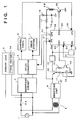
- Fig. 1 is a block diagram illustrating an embodiment of the present invention and mainly shows the electronic control circuitry (microcomputer) of a copying machine.
- an ordinary commercial power supply 1 supplies the apparatus with AC power via a power-supply outlet.
- a relay 2 which constructs a power-supply switch has a contact side 2-A and a coil side 2-B.
- the relay 2 is of the normally open type, in which the contact side 2-A is closed by energizing the coil side 2B, whereby power can be supplied to a primary load 3, which includes a fixing heater 3a and the like, and to a smoothing circuit 4.
- Fig. 1 illustrates an example in which a single-contact relay is used, it is possible to adopt an arrangement in which a two-contact relay is used to perform on/off control of both inputs of the AC power supply.
- the AC power applied to the smoothing circuit 4 is rectified and smoothed thereby so as to be converted into high-voltage DC power, which is then fed into a DC/DC converter 5.
- the latter converts the inputted high-voltage DC power into stabilized low-voltage DC power.
- the low-voltage DC power stabilized by the DC/DC converter 5 is sent to a control panel 6, which includes a display LED and such input switches as a copy key. Further, the low-voltage DC power stabilized by the DC/DC converter 5 is supplied to a drive system 7, which comprises a motor and solenoid, and to the anode of a diode 18.
- a transformer 8 is connected to the commercial power supply 1 and delivers the output of its secondary side to a smoothing unit 9. The latter rectifies and smooths this signal so as to convert it into DC power of a desired voltage.
- the output of the smoothing unit 9 is connected to the anode of a diode 16 and the emitter of a switching transistor 10.
- the base of the switching transistor 10 is connected to a manually operated switch 13 via a resistor 11.
- the switch 13 is for allowing the user to turn the apparatus power supply on and off. The contacts of this switch are closed while the switch is held depressed by the user.
- the side of the manually operated switch 13 connected to the resistor 11 is connected to an input port P1 (54) of a microcomputer 50 constituting the electronic control circuitry which administers overall control of the apparatus in this embodiment.
- the microcomputer 50 is capable of reading the operating state of the switch 13.
- the base of the switching transistor 10 is connected to the collector of a transistor 14 via a resistor 12.
- the emitter of the transistor 14 is connected to ground, and the base of the transistor 14 is connected to an output port OP1 (53) of the microcomputer 50.
- the collector of the switching transistor 10 is connected to the input of a regulator 15.
- the latter regulates this input to produce a highly stabilized output of, say, 5 V DC, which is connected to a power-supply input terminal Vcc of the microcomputer 50.
- the microcomputer 50 incorporates the control hardware of the DC/DC converter 5.
- a voltage-detection signal from the DC/DC converter 5 is applied to an input port IP2 (51) of the microcomputer 50.
- the output from an output port OP3 (52) is controlled (as by PWM control) in dependence upon the inputted voltage-detection signal.
- the output of the DC/DC converter 5 is controlled so as to be a fixed voltage by the signal from the output port OP3 (52). It should be noted that control for halting the output from the output port OP3 (52) and for delivering the control output can be performed also by starting a program that has been stored in an internal memory of the microcomputer 50.
- the cathode of the diode 16 is connected to the cathode of the diode 18, a capacitor 19 and one end of the coil 2B of relay 2 via a resistor 17.
- the other terminal of the coil 2-B of relay 2 is connected to the collector of a transistor 20, the base of the transistor 20 is connected to an output port OP2 (55) of the microcomputer 50, and the emitter of the transistor is connected to ground.
- the control panel 6 includes manually operated switches, such as the aforementioned copy key.
- the output of the control panel 6 is inputted to an input port IP3 (56) of the microcomputer 50.
- IP3 input port of the microcomputer 50.
- the latter is capable of reading in the operating states of the manually operated switches of the control panel 6.
- Numeral 21 denotes a temperature sensor which monitors the state of the fixing section.
- the microcomputer 50 is capable also of detecting an abnormality in the fixing heater.
- the AC power is being supplied to the transformer 8, as a result of which the smoothing unit 9 is delivering the prescribed DC power.
- the DC power from the smoothing unit 9 is being supplied to the capacitor 9 via the diode 16 and resistor 17, and therefore the capacitor 19 is charged.
- the switching transistor 10 is in the cut-off state and no power is being supplied to the microcomputer 50. Consequently, there is no output at the output port OP2 (55), and the transistor 20 also is in the cut-off state. Accordingly, the coil side 2-B of the relay 2 is not being energized and the contact 2-A of relay 2 is open.
- the primary load 3 and smoothing circuit 4, etc., are cut off from the commercial power supply 1 and therefore are not being supplied with AC power.
- the microcomputer 50 After turning on its output port OP1 (53), the microcomputer 50 turns on its output port OP2 (55), thereby turning on the transistor 20.
- the coil 2-B of relay 2 is supplied with power owing to the charge that has been stored in the capacitor 19, and therefore the relay 2 is actuated to close the contacts 2-A. Consequently, upon elapse of the operating time required for closure of the contacts 2-A of relay 2, operating power is supplied to the primary load 3 and smoothing circuit 4. DC power from the smoothing circuit 4 is supplied to the DC/DC converter 5 as well.
- the microcomputer 5 places the output port OP3 (52) in the control state and, in accordance with the signal inputted to input port IP2 (51), controls the output of the DC/DC regulator 5 so that this output attains a constant voltage.
- the control panel 6 and the drive system 7 are provided with power having a constant voltage.
- the microcomputer 50 investigates the state of the input port IP2 (51), senses the port is at the low level and thus is capable of confirming that the switch 13 has been pressed.
- the microcomputer 50 finally turns off the output port OP1 (53), thereby turning off the transistor 14 and the switching transistor 10. Consequently, the supply of power Vcc to the microcomputer 50 also is stopped so that operation of the microcomputer 50 ceases.
- Step 71 is an initialization routine in which various registers incorporated within the microcomputer 50 are initially set and an internal RAM (not shown) is initially cleared.
- step 74 the output port OP2 (55) is turned on, the coil 2-B of the relay 2 is energized and the contacts 2-A are closed.
- step 75 at which the system waits for a period of time needed for operation of the relay (in this embodiment, the operating time for closure of contacts 2-A is 20 msec).
- the program proceeds to step 76 following elapse of this period of time.
- Step 78 is a copying-machine control routine, the control procedure of which is shown in Fig. 3. This routine is for executing control processing, such as for controlling the display on the control panel 6 and performing a copying operation.
- the output port OP2 (55) is turned off at step 82 and feed of current to the coil 2-B of relay 2 is terminated to open the contacts 2-A, thereby halting the supply of power to the primary load 3 and smoothing circuit 4.
- the output port OP1 (53) is then turned off at step S83, as a result of which control is performed so as to turn off the power supply of the microcomputer 50.
- the microcomputer 50 Since decay of the power supply takes some time, the microcomputer 50 eventually ceases operating while the processing of steps 71, 72 is being continued.
- the operating power supply of the apparatus in this embodiment can be on/off controlled by the switch 13, which is manipulated by the operator.
- step 78 on/off control of the power supply is performed also when the user has not operated the apparatus for a fixed period of time and when an abnormality develops in the apparatus.
- Fig. 3 is a flowchart mainly for describing control of the power supply. This is a flowchart of a program that is included in the copying-machine control routine (step 78) of Fig. 2.
- step 90 it is determined at step 90 whether a copying operation is currently in progress. If the answer is affirmative, processing proceeds to step 91, at which a copy processing routine is executed.
- a copy processing routine is executed.
- a static-electric copying sequence is executed. This entails controlling the feeding and conveyance of copy paper, the application of a high voltage to an exposure lamp, etc.
- processing proceeds from step 91 to step 96, at which the temperature sensed by the temperature sensor 21 arranged in close proximity to the fixing heater 3a is investigated to determine whether the temperature is abnormal. If the temperature of the fixing heater 3a is less than 220°C, the apparatus is judged to be operating normally and the program returns to step 90.
- step 90 If it is determined at step 90 that a copying operation is not in progress, then the program proceeds to step 92, at which it is determined whether there is a key input from the control panel 6. If there is a key input, the program proceeds to step 94, at which processing corresponding to the pressed key is executed. Thereafter, at step 95, an operation monitoring time (two minutes in this embodiment) is set in a timer T1 in the microcomputer 50. The operation monitoring time is for cutting off power, with the exception of the operating power to the microcomputer 50, when keys on the control panel have not been operated for a prescribed period of time. After the timer has been set, the program proceeds to step 96.
- step 92 the program proceeds from step 92 to step 93, where it is determined whether the timer T1 has run out of time.
- step 93 it is determined whether the timer T1 has run out of time.
- the program proceeds to step 96 if the timer T1 has not run out of time.
- step 93 If the timer T1 runs out of time at step 93, i.e., if no key on the control panel 6 is operated for two minutes, which is the operation monitoring time, the program returns to step 81 in Fig. 2. Here processing is executed for cutting off power with the exception of the operating power of the microcomputer 50.
- step 96 In a case where the temperature of the fixing heater 3a is found to be greater than 220°C at step 96, it is judged that the fixing unit has developed an abnormality and the program proceeds to step 97, at which the output port OP3 (52) is turned off to halt operation of the DC/DC converter 5.
- step 98 the output port OP2 (55) is turned off, the feed of current to the coil 2-b of relay 2 is terminated, the relay contacts 2-A are opened and the supply of power to the primary load 3 and smoothing circuit 4 is stopped.
- step 99 the program proceeds from step 99 to step 100, at which the output port OP1 (53) is turned off and control is exercised to turn off the power supply of the microcomputer 50.
- the apparatus can be greatly reduced in size and cost and improved in terms of reliability.
- the manually operated switch 13 is disposed in a low-voltage section, an ordinary tactile switch can be used.
- the relay itself is much less expensive and higher in reliability than the conventional switch.
- the relay contacts 2-A are opened after the operation of the DC/DC converter 5 is halted, and therefore the reliability of the contacts is greatly enhanced. Since the arrangement is such that on/off control of the power supplied to the load, which exhibits a large power consumption, is performed by the relay and contacts, reliability is improved and safety is enhanced. Moreover, if a tactile switch is employed as the manually operated switch 13, only a light finger pressure is required to operated the switch. This enhances operability.
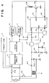
- the transformer 8 is connected to the commercial power supply 11 via the switch 13 operated manually by the user.
- the switch 13 When the manually operated switch 13 is pressed, therefore, its contacts are closed, the transformer 8 is energized, an output is produced on the secondary side of the transformer, and this output is half-wave rectified by a diode 9-1 and smoothed by a capacitor 9-2.
- Numeral 15 denotes a three-terminal regulator having an input-voltage detecting terminal. When the input voltage at an input terminal 15-1 exceeds a predetermined voltage value, the regulator 15 produces an output. The voltage at the input terminal 15-1 of the three-terminal regulator 15 and a delay time for allowing the voltage to rise are set by resistors 81, 82 and a capacitor 83.
- the output of the three-terminal regulator 15 is supplied to the power-supply terminal Vcc of the microcomputer 50 via a diode 85 and also to the coil 2-B of the relay 2 and the temperature sensor 21.
- the output of the three-terminal regulator 15 is applied to the input port IP1 (54) of the microcomputer 50, which thus is capable of discriminating the state of the three-terminal regulator 15.
- the output port OP2 (55) of the microcomputer 50 is connected to the base of the transistor 20.
- the microcomputer 50 turns on the output port OP2 (55)
- the relay coil 2-B is energized to close the relay contacts 2-A.
- the AC power supply 1 is fed to the smoothing circuit 4 where it is smoothed and then delivered to the DC/DC converter 5.
- direct control of the DC/DC converter 5 by the microcomputer 50 is eliminated. Consequently, upon being supplied with electric power from the smoothing circuit 4, the DC/DC converter 5 immediately produces a stabilized constant-voltage output independently without being externally controlled.
- the output of the DC/DC converter 5 is connected to the control panel 6 and drive system 7 to supply these with operating power.
- the output of the DC/DC converter 5 supplies power also to the anode side of a diode 84 so that the driving power Vcc is supplied to the microcomputer 50 via this diode. Consequently, the driving power Vcc will be supplied from the DC/DC converter 5 even when the manually operated switch 13 is subsequently released to halt the supply of power from the three-terminal regulator 15.
- Electric power is not supplied to the transformer 8, primary load 3 and smoothing circuit 4 when the user is not pressing the switch 13.
- the microcomputer 50 When the microcomputer 50 is thus activated, it executes operations substantially similar to those of the first embodiment. Specifically, first the output port OP2 is turned on to close the contacts 2-A of relay 2. As a result, the AC power supply 1 supplies electric power to the primary load 3 and smoothing circuit 4. In addition, the DC/DC converter 5 produces an output.
- the control panel 6 and driving system are supplied with operating power, and power is supplied also to the microcomputer 50 via the diode 84. Even when the user releases the manually operated switch 13, therefore, power continues to be supplied to the microcomputer 50.
- the apparatus of the second embodiment executes well-known copying processing.
- the output of the three-terminal regulator 15 becomes 5 V, in the manner described above.
- the microcomputer 50 constantly monitors whether there is an input from the switch 13. Owing to the aforementioned depression of switch 13, there is an input from the switch and, hence, the state of the input port IP1 (54) temporarily becomes “1". When the switch 13 is subsequently released, the state of the input port IP1 (54) reverts to "0".
- the flowchart of Fig. 2 substantially applies also to operation of the microcomputer 50 in this embodiment.
- steps 73, 75, 76, 81 and 83 should be deleted from the flowchart of Fig. 2 and the logic levels in steps 72, 77, 79 and 80, at which the logic level of the input port IP1 (54) is judged, should be reversed.
- a further description of the operational flow is omitted for the sake of simplicity and brevity.
- the processing at the occurrence of an abnormality, as well as the processing when there is no input from a key for a prescribed period of time, is substantially the same as that described earlier.
- the present invention may be applied to a system composed of a plurality of apparatus or only to a single apparatus. Also, it goes without saying that the invention is applicable also to a case where the invention is achieved by supplying a program to the system or apparatus.
- the apparatus is reduced in size and cost, the power consumption of the apparatus is reduced, suitable control is performed when an abnormality occurs, reliability is enhanced and operability is improved at the same time.
- an image processing apparatus in which, when the apparatus has not been not used for a prescribed period of time, control is performed so as to halt feed of current not only to a display unit and fixing heater but also to other components not required to operate when the apparatus is not in use, and in which on/off control of the power supply also can be performed through a more compact and less expensive arrangement.
- a manually operated switch is being pressed by an operator, a transistor is turned on via the contacts of the switch so that power from a smoothing unit is applied to a regulator.
- the regulator supplies operating power to a microcomputer, which subsequently controls the status of the apparatus power supply depending upon the on/off state of an output port of the microcomputer.
- Supply of driving power to other components of the apparatus is achieved by opening and closing contacts through control of a relay in response to an output from another output port of the microcomputer.
Landscapes
- Engineering & Computer Science (AREA)
- Physics & Mathematics (AREA)
- General Physics & Mathematics (AREA)
- Power Engineering (AREA)
- Microelectronics & Electronic Packaging (AREA)
- Control Or Security For Electrophotography (AREA)
- Direct Current Feeding And Distribution (AREA)
- Accessory Devices And Overall Control Thereof (AREA)
- Fixing For Electrophotography (AREA)
Applications Claiming Priority (2)
| Application Number | Priority Date | Filing Date | Title |
|---|---|---|---|
| JP34052/91 | 1991-02-28 | ||
| JP3034052A JPH04273257A (ja) | 1991-02-28 | 1991-02-28 | 電力供給制御装置及び画像処理装置 |
Publications (3)
| Publication Number | Publication Date |
|---|---|
| EP0501496A2 true EP0501496A2 (de) | 1992-09-02 |
| EP0501496A3 EP0501496A3 (en) | 1993-02-24 |
| EP0501496B1 EP0501496B1 (de) | 1995-08-02 |
Family
ID=12403521
Family Applications (1)
| Application Number | Title | Priority Date | Filing Date |
|---|---|---|---|
| EP19920103402 Expired - Lifetime EP0501496B1 (de) | 1991-02-28 | 1992-02-27 | Bildverarbeitungsgerät |
Country Status (4)
| Country | Link |
|---|---|
| US (2) | US5670832A (de) |
| EP (1) | EP0501496B1 (de) |
| JP (1) | JPH04273257A (de) |
| DE (1) | DE69203751T2 (de) |
Cited By (1)
| Publication number | Priority date | Publication date | Assignee | Title |
|---|---|---|---|---|
| FR2785065A1 (fr) * | 1998-10-27 | 2000-04-28 | Hewlett Packard Co | Procede d'exclusion temporaire de travaux d'impression sur un copieur de reseau lorsqu'un utilisateur en libre service est present |
Families Citing this family (13)
| Publication number | Priority date | Publication date | Assignee | Title |
|---|---|---|---|---|
| JP3658055B2 (ja) * | 1995-10-12 | 2005-06-08 | キヤノン株式会社 | 画像形成装置の電源制御装置 |
| US5832340A (en) * | 1996-04-09 | 1998-11-03 | Minolta Co., Ltd. | Image forming apparatus |
| JP3391186B2 (ja) * | 1996-07-10 | 2003-03-31 | ミノルタ株式会社 | 電源制御装置 |
| US5884122A (en) * | 1996-07-10 | 1999-03-16 | Minolta Co., Ltd. | Image forming apparatus |
| KR100247275B1 (ko) * | 1997-04-18 | 2000-03-15 | 윤종용 | 절전형 스크린 세이버 기능을 갖는 컴퓨터 시스템 및 그 제어방법 |
| US6093916A (en) * | 1997-10-06 | 2000-07-25 | Canon Kabushiki Kaisha | Control device with first and second power control elements to control heater drive apparatus |
| JP2001334727A (ja) * | 2000-05-29 | 2001-12-04 | Murata Mach Ltd | 画像形成装置 |
| US6393233B1 (en) * | 2000-10-24 | 2002-05-21 | Hewlett-Packard Company | Printer fuser power management |
| JP2004023918A (ja) * | 2002-06-18 | 2004-01-22 | Sankyo Seiki Mfg Co Ltd | 電源制御回路 |
| JP5246239B2 (ja) * | 2010-10-01 | 2013-07-24 | 株式会社日本自動車部品総合研究所 | 電力供給装置 |
| JP5834790B2 (ja) | 2011-11-09 | 2015-12-24 | ブラザー工業株式会社 | 電源システム、同電源システムを備えた画像形成装置および電源システムの制御方法 |
| JP6020219B2 (ja) | 2013-02-06 | 2016-11-02 | ブラザー工業株式会社 | 電源システム |
| JP6044380B2 (ja) * | 2013-02-18 | 2016-12-14 | ブラザー工業株式会社 | 電源システム、同電源システムを備えた画像形成装置 |
Family Cites Families (17)
| Publication number | Priority date | Publication date | Assignee | Title |
|---|---|---|---|---|
| US3669412A (en) * | 1968-12-31 | 1972-06-13 | Minolta Camera Kk | Circuitry for controlling an electrostatic copier |
| JPS5479042A (en) * | 1977-12-06 | 1979-06-23 | Canon Inc | Image forming device |
| JPS5485730A (en) * | 1977-12-20 | 1979-07-07 | Canon Inc | Control device for copying |
| JPS5695247A (en) * | 1979-12-28 | 1981-08-01 | Canon Inc | Image forming device |
| US4467246A (en) * | 1980-08-28 | 1984-08-21 | Canon Kabushiki Kaisha | Light quantity controller and input device |
| JPS58117562A (ja) * | 1981-12-31 | 1983-07-13 | Konishiroku Photo Ind Co Ltd | 記録装置のオ−トシヤツトオフ装置 |
| DE3303220A1 (de) * | 1983-02-01 | 1984-08-02 | Bayer Ag, 5090 Leverkusen | Verfahren zur gleichzeitigen gewinnung von 4-hydroxydiphenyl und 4,4'-dihydroxydiphenyl |
| US4468715A (en) * | 1983-05-09 | 1984-08-28 | Zenith Electronics Corporation | On/off and shutdown circuit for CRT projection system |
| US4538074A (en) * | 1983-08-24 | 1985-08-27 | Healthcheck Corporation | Power switch |
| US4825250A (en) * | 1984-08-30 | 1989-04-25 | Canon Kabushiki Kaisha | Image forming apparatus including exposure scanning means |
| US4766404A (en) * | 1985-11-18 | 1988-08-23 | Canon Kabushiki Kaisha | Coordinate input apparatus |
| JPS6367602A (ja) * | 1986-09-09 | 1988-03-26 | Minolta Camera Co Ltd | 自動電源オフシステム |
| JPS63180989A (ja) * | 1987-01-23 | 1988-07-26 | Fuji Xerox Co Ltd | 安全装置 |
| JPH0263067A (ja) * | 1988-08-30 | 1990-03-02 | Konica Corp | 画像作成装置の安全装置 |
| JPH0268570A (ja) * | 1988-09-02 | 1990-03-08 | Konica Corp | 画像記録装置の電源装置 |
| DE69330410T2 (de) * | 1992-02-21 | 2002-05-29 | Sanyo Electric Co., Ltd. | Steuerungsgerät für Wechselspannungsquelle |
| KR960010183B1 (ko) * | 1993-10-23 | 1996-07-26 | 김광호 | 에너지절감 화상기록장치 및 그 제어방법 |
-
1991
- 1991-02-28 JP JP3034052A patent/JPH04273257A/ja active Pending
-
1992
- 1992-02-27 EP EP19920103402 patent/EP0501496B1/de not_active Expired - Lifetime
- 1992-02-27 DE DE69203751T patent/DE69203751T2/de not_active Expired - Lifetime
-
1994
- 1994-11-22 US US08/347,170 patent/US5670832A/en not_active Expired - Lifetime
-
1997
- 1997-06-25 US US08/882,032 patent/US5760494A/en not_active Expired - Lifetime
Cited By (1)
| Publication number | Priority date | Publication date | Assignee | Title |
|---|---|---|---|---|
| FR2785065A1 (fr) * | 1998-10-27 | 2000-04-28 | Hewlett Packard Co | Procede d'exclusion temporaire de travaux d'impression sur un copieur de reseau lorsqu'un utilisateur en libre service est present |
Also Published As
| Publication number | Publication date |
|---|---|
| DE69203751D1 (de) | 1995-09-07 |
| JPH04273257A (ja) | 1992-09-29 |
| EP0501496A3 (en) | 1993-02-24 |
| DE69203751T2 (de) | 1995-12-21 |
| US5760494A (en) | 1998-06-02 |
| US5670832A (en) | 1997-09-23 |
| EP0501496B1 (de) | 1995-08-02 |
Similar Documents
| Publication | Publication Date | Title |
|---|---|---|
| EP0501496B1 (de) | Bildverarbeitungsgerät | |
| US7040727B2 (en) | Apparatus for controlling power supply to printer and method thereof | |
| US6331699B1 (en) | Microwave heating apparatus requiring reduced power in a standby state | |
| US5631504A (en) | AC/DC power supply | |
| US4426144A (en) | Power supply unit shared by camera's motor drive and electronic flash | |
| CA2038662C (en) | Apparatus for driving the armature of an electric stapler | |
| US4381459A (en) | Power-up circuit for microprocessor based appliance control | |
| JP2001145354A (ja) | 電気機器の低消費電力スタンバイ電源回路 | |
| JPH0923644A (ja) | スイッチング電源装置 | |
| EP1051846A1 (de) | Erzeugung eines aus/einschaltungssignals der stromversorgung | |
| JPH1097355A (ja) | マイクロコンピュータの電源回路 | |
| KR100315809B1 (ko) | 세탁기의 전원장치 | |
| JP3294328B2 (ja) | 制御電源装置 | |
| JP3237447B2 (ja) | アイロン | |
| JPH10337017A (ja) | スイッチング電源装置 | |
| KR940006486B1 (ko) | 가정용 음전위 치료기 | |
| KR0126841Y1 (ko) | 입력전압 안정화 회로 | |
| KR0149403B1 (ko) | 마이크로컴퓨터 사용기기 | |
| JP3855380B2 (ja) | タイマ装置 | |
| KR950005690Y1 (ko) | 제어장치의 초기화회로 | |
| JPH08205399A (ja) | Acアダプタ | |
| KR0155279B1 (ko) | 전기세탁기의 전압자동 절환회로 | |
| KR0147997B1 (ko) | 브이.씨.알의 전원 제어 방법 | |
| JPS6347022Y2 (de) | ||
| JPS5816101Y2 (ja) | 遅延リレ−回路 |
Legal Events
| Date | Code | Title | Description |
|---|---|---|---|
| PUAI | Public reference made under article 153(3) epc to a published international application that has entered the european phase |
Free format text: ORIGINAL CODE: 0009012 |
|
| AK | Designated contracting states |
Kind code of ref document: A2 Designated state(s): DE FR GB IT |
|
| PUAL | Search report despatched |
Free format text: ORIGINAL CODE: 0009013 |
|
| AK | Designated contracting states |
Kind code of ref document: A3 Designated state(s): DE FR GB IT |
|
| 17P | Request for examination filed |
Effective date: 19930712 |
|
| 17Q | First examination report despatched |
Effective date: 19940915 |
|
| GRAA | (expected) grant |
Free format text: ORIGINAL CODE: 0009210 |
|
| AK | Designated contracting states |
Kind code of ref document: B1 Designated state(s): DE FR GB IT |
|
| REF | Corresponds to: |
Ref document number: 69203751 Country of ref document: DE Date of ref document: 19950907 |
|
| ET | Fr: translation filed | ||
| ITF | It: translation for a ep patent filed | ||
| PLBE | No opposition filed within time limit |
Free format text: ORIGINAL CODE: 0009261 |
|
| STAA | Information on the status of an ep patent application or granted ep patent |
Free format text: STATUS: NO OPPOSITION FILED WITHIN TIME LIMIT |
|
| 26N | No opposition filed | ||
| REG | Reference to a national code |
Ref country code: GB Ref legal event code: IF02 |
|
| PGFP | Annual fee paid to national office [announced via postgrant information from national office to epo] |
Ref country code: IT Payment date: 20100215 Year of fee payment: 19 Ref country code: FR Payment date: 20100315 Year of fee payment: 19 |
|
| PGFP | Annual fee paid to national office [announced via postgrant information from national office to epo] |
Ref country code: DE Payment date: 20100228 Year of fee payment: 19 Ref country code: GB Payment date: 20100219 Year of fee payment: 19 |
|
| GBPC | Gb: european patent ceased through non-payment of renewal fee |
Effective date: 20110227 |
|
| REG | Reference to a national code |
Ref country code: FR Ref legal event code: ST Effective date: 20111102 |
|
| PG25 | Lapsed in a contracting state [announced via postgrant information from national office to epo] |
Ref country code: IT Free format text: LAPSE BECAUSE OF NON-PAYMENT OF DUE FEES Effective date: 20110227 |
|
| REG | Reference to a national code |
Ref country code: DE Ref legal event code: R119 Ref document number: 69203751 Country of ref document: DE Effective date: 20110901 |
|
| PG25 | Lapsed in a contracting state [announced via postgrant information from national office to epo] |
Ref country code: FR Free format text: LAPSE BECAUSE OF NON-PAYMENT OF DUE FEES Effective date: 20110228 |
|
| PG25 | Lapsed in a contracting state [announced via postgrant information from national office to epo] |
Ref country code: GB Free format text: LAPSE BECAUSE OF NON-PAYMENT OF DUE FEES Effective date: 20110227 |
|
| PG25 | Lapsed in a contracting state [announced via postgrant information from national office to epo] |
Ref country code: DE Free format text: LAPSE BECAUSE OF NON-PAYMENT OF DUE FEES Effective date: 20110901 |