EP0501513A2 - Anrufverteilsystem für mehrere Endgeräte - Google Patents
Anrufverteilsystem für mehrere Endgeräte Download PDFInfo
- Publication number
- EP0501513A2 EP0501513A2 EP92103476A EP92103476A EP0501513A2 EP 0501513 A2 EP0501513 A2 EP 0501513A2 EP 92103476 A EP92103476 A EP 92103476A EP 92103476 A EP92103476 A EP 92103476A EP 0501513 A2 EP0501513 A2 EP 0501513A2
- Authority
- EP
- European Patent Office
- Prior art keywords
- target receiver
- receiver terminal
- idle
- call
- busy
- Prior art date
- Legal status (The legal status is an assumption and is not a legal conclusion. Google has not performed a legal analysis and makes no representation as to the accuracy of the status listed.)
- Granted
Links
Images







Classifications
-
- H—ELECTRICITY
- H04—ELECTRIC COMMUNICATION TECHNIQUE
- H04M—TELEPHONIC COMMUNICATION
- H04M3/00—Automatic or semi-automatic exchanges
- H04M3/42—Systems providing special services or facilities to subscribers
- H04M3/50—Centralised arrangements for answering calls; Centralised arrangements for recording messages for absent or busy subscribers ; Centralised arrangements for recording messages
- H04M3/51—Centralised call answering arrangements requiring operator intervention, e.g. call or contact centers for telemarketing
- H04M3/5158—Centralised call answering arrangements requiring operator intervention, e.g. call or contact centers for telemarketing in combination with automated outdialling systems
-
- H—ELECTRICITY
- H04—ELECTRIC COMMUNICATION TECHNIQUE
- H04M—TELEPHONIC COMMUNICATION
- H04M3/00—Automatic or semi-automatic exchanges
- H04M3/42—Systems providing special services or facilities to subscribers
- H04M3/50—Centralised arrangements for answering calls; Centralised arrangements for recording messages for absent or busy subscribers ; Centralised arrangements for recording messages
- H04M3/51—Centralised call answering arrangements requiring operator intervention, e.g. call or contact centers for telemarketing
- H04M3/523—Centralised call answering arrangements requiring operator intervention, e.g. call or contact centers for telemarketing with call distribution or queueing
-
- H—ELECTRICITY
- H04—ELECTRIC COMMUNICATION TECHNIQUE
- H04Q—SELECTING
- H04Q3/00—Selecting arrangements
- H04Q3/0016—Arrangements providing connection between exchanges
- H04Q3/0029—Provisions for intelligent networking
-
- H—ELECTRICITY
- H04—ELECTRIC COMMUNICATION TECHNIQUE
- H04Q—SELECTING
- H04Q3/00—Selecting arrangements
- H04Q3/42—Circuit arrangements for indirect selecting controlled by common circuits, e.g. register controller, marker
- H04Q3/47—Circuit arrangements for indirect selecting controlled by common circuits, e.g. register controller, marker using translators
-
- H—ELECTRICITY
- H04—ELECTRIC COMMUNICATION TECHNIQUE
- H04M—TELEPHONIC COMMUNICATION
- H04M2242/00—Special services or facilities
- H04M2242/22—Automatic class or number identification arrangements
-
- H—ELECTRICITY
- H04—ELECTRIC COMMUNICATION TECHNIQUE
- H04M—TELEPHONIC COMMUNICATION
- H04M3/00—Automatic or semi-automatic exchanges
- H04M3/42—Systems providing special services or facilities to subscribers
- H04M3/42025—Calling or Called party identification service
- H04M3/42034—Calling party identification service
- H04M3/42059—Making use of the calling party identifier
-
- H—ELECTRICITY
- H04—ELECTRIC COMMUNICATION TECHNIQUE
- H04M—TELEPHONIC COMMUNICATION
- H04M3/00—Automatic or semi-automatic exchanges
- H04M3/42—Systems providing special services or facilities to subscribers
- H04M3/50—Centralised arrangements for answering calls; Centralised arrangements for recording messages for absent or busy subscribers ; Centralised arrangements for recording messages
- H04M3/53—Centralised arrangements for recording incoming messages, i.e. mailbox systems
- H04M3/533—Voice mail systems
-
- H—ELECTRICITY
- H04—ELECTRIC COMMUNICATION TECHNIQUE
- H04Q—SELECTING
- H04Q2213/00—Indexing scheme relating to selecting arrangements in general and for multiplex systems
- H04Q2213/13072—Sequence circuits for call signaling, ACD systems
-
- H—ELECTRICITY
- H04—ELECTRIC COMMUNICATION TECHNIQUE
- H04Q—SELECTING
- H04Q2213/00—Indexing scheme relating to selecting arrangements in general and for multiplex systems
- H04Q2213/13547—Indexing scheme relating to selecting arrangements in general and for multiplex systems subscriber, e.g. profile, database, database access
-
- H—ELECTRICITY
- H04—ELECTRIC COMMUNICATION TECHNIQUE
- H04Q—SELECTING
- H04Q3/00—Selecting arrangements
- H04Q3/72—Finding out and indicating number of calling subscriber
Definitions
- the present invention relates to a number conversion service system for converting a dialed number to a receiving telephone number. It can be realized in communication networks such as telephone switching networks.
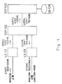
- An intelligent network (IN) capable of providing such switching services accommodates a data base (DB) 104 for use in each service as shown in Figure 1, and comprises a service control point (SCP) 103 for controlling all services, a service switching point (SSP) 102 for providing accessing and switching service capabilities for the SCP 103, and a subscriber line switching unit (LS) 101 for accommodating subscribers.
- SCP service control point
- SSP service switching point
- LS subscriber line switching unit
- a number conversion service is one of the services provided by such an intelligent network. This service permits a call to be received by a target receiver by dialing an identification number of a registered receiver without dialing the actual telephone number of the target receiver.
- STEP 1 Issuing a call
- SAC service access code
- UI registered receiver identification number
- STEP 2 Accepting an issue of a call
- the LS 101 On detecting an issue of a call, the LS 101 relays issue-of-call information to the SSP 102 by interpreting the SAC according to the common call procedure .
- STEP 3 Inquiry about a number
- the SSP 102 On receiving the SAC + UI from the LS 101, the SSP 102 recognizes a number conversion service by interpreting the SAC, notifies the number conversion service unit in the SCP 103 of a receiver inquiry request, and waits for a response. Thus, the SSP 102 performs a service access function.
- the SCP 103 On receiving a receiver inquiry, the SCP 103 accesses a number conversion table 201 as shown in Figure 2 which is stored in the DB 104 connected to the SCP 103.
- the SCP 103 reads a corresponding DN by accessing the number conversion table 201 according to received SAC and UI, and then notifies the SSP 102 of the DN as a receiver's telephone number.
- the SSP 102 relays a call from the sender A to the LS 101 to accommodate receiving terminals.
- the SSP 102 acts as a switching unit.
- STEP 6 Receiving a call
- a call is normally processed by the LS 101 on the receiving side.
- a target terminal is idle, a ringing tone is raised.
- a ringback tone is simultaneously sent to the sender A.
- a busy tone is raised.
- a dialed number corresponds to a eceiver's telephone number. Therefore, a dialed number is always converted to a registered receiver's telephone number regardless of the state of a target terminal, and a call receiving process is performed for the telephone number.
- the present invention has been developed based on the above described background and aims at providing improved services for senders with the smallest possible number of unsuccessful calls by enabling a plurality of receiver's telephone numbers to be connected. It also aims at providing a good service for a registered number conversion service user by distributing calls among a plurality of terminals.
- the present invention relates to a number conversion service in which a switching unit permits a call from a user to be received by a corresponding target receiver terminal by converting a user-specified service access code and a registered receiver identification number to a target receiver terminal number.
- the present invention has a configuration comprising a target receiver terminal information storage unit and a control unit.
- the target receiver terminal information storage unit is for storing for each registered receiver identification number plural sets of a target receiver terminal number and its idle/busy information indicating the idle/busy state for a plurality of target receiver terminals.
- the control unit is for selecting, based on a predetermined priority from the target receiver terminal information storage unit according to the user-specified service access code and registered receiver identification number, one of the target receiver terminal numbers in the idle state according to the idle/busy information; outputting the selected number to a switching unit; and updating idle/busy information stored by the target receiver terminal information storage unit according to the idle/busy state of each target receiver terminal.
- a sender can automatically call up an appropriate target receiver terminal based on the priority by dialing only one registered receiver identification number.
- the present invention provides improved services to senders with the smallest possible number of unsuccessful calls by enabling a plurality of receiver's telephone numbers to be selectively called up. It also aims at providing a good service to a registered number conversion service user by distributing a call to a plurality of terminals.
- the present invention relates to a number conversion service system for permitting a call from a ser to be received by a target receiver terminal through a switching unit by converting a user-dialed (specified) service access code and registered receiver identification number to a target receiver terminal number in a communication network such as a telephone networks.
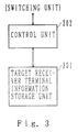
- FIG 3 is a block diagram for explaining the principle of the present invention.
- the present invention comprises a target receiver terminal information storage unit 301 and a control unit 302. These units are provided in an exclusive service controller (service control point) connected to a switching unit, for example. Otherwise, they can be included as functions in the switching unit.
- an exclusive service controller service control point
- the first aspect of the present invention can be configured as follows.
- the target receiver terminal information storage unit 301 stores for each registered receiver identification number, plural sets of a target receiver terminal number and its idle/busy information indicating the idle/busy state.
- the control unit 302 selects from the target receiver terminal information storage unit 301, based on a predetermined priority (for example, in the memory address order), one of the target receiver terminal numbers whose idle/busy information indicates "idle", and then outputs the selected number to a switching unit. According to the idle/busy state of each target receiver terminal, the control unit 302 updates the idle/busy information stored in the target receiver terminal information storage unit.
- the second aspect of the present invention has the following configuration.
- the target receiver terminal information storage unit 301 stores for each registered receiver identification number plural sets of a target receiver terminal number, its idle/busy information indicating the idle/busy state, and connection information indicating the connection state of the corresponding terminal.
- the connection information contains, for example, the maximum number of call connections for each target receiver terminal in a predetermined time period, the actual number of call connections in a predetermined time period, and the connection rate, that is, the ratio of the actual number of connections to the maximum number.
- the control unit 302 selects from the target receiver terminal information storage unit 301 one of the target receiver terminal numbers whose idle/busy information indicates "idle” based on the connection information stored with the corresponding target receiver terminal number as a pair. Then, the control unit 302 outputs the selected number to a switching unit. That is, from among the target receiver terminal numbers whose idle/busy information indicates "idle", a number indicating the smallest connection rate is selected and outputted to a switching unit.
- the control unit 302 updates the idle/busy information and the connection information stored in the target receiver terminal information storage unit. That is, the idle/busy information which is stored with a target receiver terminal number as a pair, the connection number, and the connection rate are updated. Then, according to the idle/busy state and the connection state of a target receiver terminal, the idle/busy information, the actual number of connections, and the connection rate which are stored in the target receiver terminal information storage unit are updated.
- the third aspect of the present invention has the following configuration.
- the target receiver terminal information storage unit 301 stores for each registered receiver identification number a plurality of target receiver terminal numbers each corresponding to a plurality of target receiver terminals. In this case, the idle/busy information, etc. is not required.
- the control unit 302 selects from the target receiver terminal information storage unit 301 one of the target receiver terminal numbers based on the next selection information. Then, the control unit 302 outputs the selected number to a switching unit. If the control unit 302 is notified by the switching unit side of the busy state of the outputted target receiver terminal number, another target receiver terminal number is selected and outputted, and the next selection information is updated.
- a communication unit is provided to receive from the switching unit side a notification that the outputted target receiver terminal number described above is "busy".
- the target receiver terminal information storage unit 301 stores for a plurality of target receiver terminals plural sets of a target receiver terminal number and its idle/busy information indicating the idle/busy state.
- the control unit 302 selects the target receiver terminal information storage unit 301 in a predetermined group related to a predetermined registered receiver identification number. Then, the control unit 302 selects from the above described storage unit 301 one of the target receiver terminal numbers whose idle/busy information indicates the idle state according to a predetermined priority, outputs the selected number to a switching unit, and updates the idle/busy information stored in the target receiver terminal information storage unit 301 according to the idle/busy state of each target receiver terminal.
- the present invention has the following configuration in its fifth aspect.
- a maximum connection number determiner not shown in Figure 1, for determining the maximum number of call connections which can be made in a target receiver terminal within a predetermined time period based on one or more of the present date, the day of the week, and the time period.
- the target receiver terminal information storage unit 301 stores for each registered receiver identification number plural sets of a target receiver terminal number, its idle/busy information indicating the idle/busy state of the corresponding terminal, and connection information indicating the connection state of the corresponding terminal.
- the connection information is stored as the actual number of call connections made within a predetermined time period associated with a target receiver terminal corresponding to the registered receiver identification number containing the connection information.
- the control unit 302 selects from the target receiver terminal information storage unit 301 one of he target receiver terminal numbers whose idle/busy information indicates the idle state according to the actual number of connections stored as pairs with the corresponding target receiver terminal number and to the maximum number of connections determined by the maximum connection number determiner, and then the control unit outputs the selected number to a switching unit.
- the target receiver terminal information storage unit 301 stores a plurality of target receiver terminal numbers corresponding to a plurality of target receiver terminals.
- control unit 302 determines idle/busy information stored in the storage unit 301 with a terminal number as a pair, selects one target receiver terminal number based on a predetermined priority, and then outputs the selected number to a switching unit.
- a sender can automatically call an appropriate target receiver terminal according to a predetermined priority only by dialing a registered receiver identification number.
- control unit 302 uses idle/busy information and onnection information as determination elements in selecting a target receiver terminal number. Therefore, calls to be received can be selectively distributed among a plurality of target receiver terminal numbers at the request of a registered number conversion service user, and a call is prevented from concentrating on a low reception capacity terminal.
- a plurality of target receiver terminal numbers are selected in response to an idle/busy inquiry to a switching unit side, and an automatic reception by a plurality of terminals can be thus realized without retaining idle/busy information.
- the control unit 302 selects the target receiver terminal information storage unit 301 in a predetermined group related to a predetermined registered receiver identification number. Therefore, each user can connect a call to the receiver's telephone number nearest the sender's area by registering it to the target receiver terminal information storage unit 301 corresponding to each group a receiver's telephone number near the sender's area corresponding to each group.
- a target receiver terminal number is selected according to the connection information.
- the connection information contains the actual number of call connections made to a corresponding target receiver terminal within a predetermined time period and the maximum number of call connections made to a corresponding target receiver terminal within a predetermined time period.
- the maximum number of connections can be determined based on one or more of the present date, the day of the week, and the time period. Therefore, a target receiver can be changed based on the date, the day of the week, and the time period.
- the general configuration of the preferred embodiment of the present invention is the same as that of a common intelligent network shown in Figure 1.
- the feature of the preferred embodiment of the present invention resides in the configuration of the SCP 103 and the internal data configuration of the DB 104.
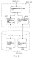
- Figure 4 shows the configuration of the SCP 103 and the DB 104 shown in Figure 1 of the preferred embodiment of the present invention.
- the preferred embodiment comprises a number conversion table 404 and a DN management table 405 in the DB 104.
- Each registered number conversion service user can register a plurality of directory numbers DN in the DN management table 405.
- a communication unit 401 sends and receives control information to and from the SSP 102 and the LS 101 (refer to Figure 1).
- the number conversion table controller 402 accesses the number conversion table 404 in the DB 104, reads the information in the DN management table 405, and notifies the DN management table controller 403 of the information.
- the DN management table controller 403 accesses the DN management table in the DB 104 according to the information provided by the number conversion table controller 402, and performs a control by normally selecting one of a plurality of DNs.
- the selection information is provided to and from the communication unit 401 to the receiving L2 101 (refer to Figure 1) through the SSP 102.
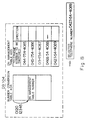
- Figure 5 shows the data configuration of the first preferred embodiment of the number conversion service system based on the configuration shown in Figure 4.
- Each DN management table 405 in the DB 104 stores a plurality of directory numbers DN (telephone number to be switched) registered by each registered number conversion service user, and idle/busy information is added to each DN.
- DN telephone number to be switched
- the DN management table 405 is accessed by the DN management table controller 403 shown in Figure 4.
- he DN management table controller 403 controls the selection of the DNs such that the DN having the highest priority of the DNs stored in the DN management table 405 can receive a call.
- a DN having a higher priority is stored at a higher order in a table. Therefore, the DN management table controller 403 sequentially determines the idle/busy state of each terminal starting from a higher order address in the DN management table 405, and selects the first-detected idle DN.
- a call process management memory 501 as shown in Figure 5 is provided in each LS 101 (refer to Figure 1).
- STEP 1 Issuing a call
- SAC service access code
- UI registered receiver identification number
- STEP 2 Accepting an issue of a call
- the LS 101 On detecting an issue of a call, the LS 101 relays issue-of-call information to the SSP 102 according to the common call procedure by interpreting the SAC.
- STEP 3 Inquiry about a number
- the SSP 102 On receiving the SAC + UI from the LS 101, the SSP 102 recognizes a number conversion service by nterpreting the SAC, notifies using SAC + UI the number conversion service unit in the SCP 103 of a receiver inquiry request, and waits for a response.
- the communication unit 401 (shown in Figure 4) in the SCP 103 notifies the number conversion table controller 402 of the above described SAC + UI.
- the controller accesses the number conversion table 404 in the DB 104 using the SAC + UI, and notifies the DN management table controller 403 of the DN management table number.
- the DN management table controller 403 accesses a corresponding DN management table 405 in the DB 104. After sequentially determining idle/busy information Starting from a higher order address in the table to select an idle DN and notify the SSP 102 of the selected DN as a receiver's telephone number.
- the SSP 102 relays a call from a sender A to the LS 101 to accommodate a receiving terminal.
- STEPS 6 and 7 Receiving a call
- a call is normally processed in the LS 101 on the receiving side and received by a corresponding terminal C.
- the LS 101 which accommodates the terminal C deletes a corresponding dial number SAC + UI and a receiver's telephone number DN from the call process management memory 501.
- the SSP 102 gives a disconnection notification to the SCP 103.
- the communication unit 401 in the SCP 103 On receiving a disconnection notification, the communication unit 401 in the SCP 103 sands the received SAC+UI and DN to the DN management table controller 403.
- the controller accesses the DN management table 405 in the DB 104, and sets idle/busy information about a corresponding address to "idle".
- a sender can automatically call an appropriate registered receiver terminal based on a predetermined priority by dialing one registered receiver identification number UI.
- the LS 101 When a call is normally received by each terminal, the LS 101 notifies the SCP 103 through the SSP 102 of the reception. Then the DN management table controller 403 shown in Figure 4 retrieves the DN management table 405 and sets the idle/busy state of the receiver's telephone numbers having the same address to "busy".
- Figure 7 shows a data configuration of the second preferred embodiment of a number conversion service system based on the configuration shown in Figure 4.
- the basic operational sequence is the same as that of the first preferred embodiment shown in Figure 6.
- the configuration of the DN management table 405 of the DB 104 is different from that of the first preferred embodiment shown in Figure 5. That is, in the configuration shown in Figure 7, number-of-connection information for distributing a load is given in addition to the idle/busy information shown in Figure 5. Thus, a call to be received can be selectively distributed to a plurality of receiver's telephone numbers at the request of a registered number conversion service user.
- the number-of-connection information comprises for each telephone number to be switched (DN) the maximum number of connections which can be made within a predetermined time period, the actual number of calls connected within a predetermined time period, and the connection rate calculated based on these values.
- connection rate can be calculated by dividing the actual number of connections by the maximum number of connections as shown in Figure 7. This shows the ratio of the number of actual connections to the maximum number of connections made to a receiving terminal of each DN within a predetermined time period.
- the connection rate of each DN is updated by the DN management table controller 403 shown in Figure 4 each time a receiving terminal corresponding to a DN is made.
- the DN management table controller 403 shown in Figure 4 selects a DN having the smallest connection rate of the idle DNs in the DN management table 405 in the number converting process in STEP 4 shown in Figure 6. Then, the SSP 102 notifies the LS 101 of the selected DN as a receiver's telephone number.
- a call can be assigned to an appropriate terminal depending on the maximum number of connections determined for each receiving terminal, thus preventing concentration of calls reception by a terminal having a small reception capacity.
- the DN management table controller 403 When all idle DNs indicate the same connection rate, the DN management table controller 403 operates such that the DN having the largest maximum number of connections can be selected. When all DNs have the same maximum number of connections, loads are evenly distributed to each receiving terminal.
- Figure 8 shows a data configuration of the third preferred embodiment of a number conversion service system based on the configuration shown in Figure 4.
- idle/busy information is provided in the DN management table 405.
- the idle/busy information is not provided in the DN management table 405.
- the call process management memory 01 in the LS 101 of a receiving terminal does not have to store a dial number SAC+UI. Only the next selection pointer for pointing to the DN to be selected next is provided in the DN management table 405.
- Each operation in issuing a call in STEP 1, in receiving a call in STEP 2, and in inquiring a number in STEP 3 is the same as that in the first and second preferred embodiments shown in Figure 6.
- the communication unit 401 ( Figure 4) in the SCP 103 notifies the number conversion table controller 402 of the above described SAC + UI.
- the controller accesses the number conversion table 404 in the DB 104, and notifies the DN management table controller 403 of the DN management table number.
- the DN management table controller 403 accesses a corresponding DN management table 405 in the DB 104. Then, a next selection pointer points to a DN to be selected from the same table, and notifies the SSP 102 of the selected DN as a receiver's telephone number. The DN management table controller 403 updates the address pointed by the next selection pointer. The update can be realized as a movement of the next selection pointer to the next address.
- the SSP 102 relays a call from a sender A to the LS 101 for accommodating a receiving terminal.
- STEPS 6-10 Receiving a call after repeating the conversion of a number in response to "busy" information
- a call is normally processed by the LS 101 on the receiving side.
- a busy notification is given to the SCP 103 through the SSP 102.
- the notification is sent to the DN management table controller 403 through the communication unit 401 shown in Figure 4.
- the controller selects the DN specified by the next selection pointer from among the DNs in the DN management table 405.
- the selected DN is provided for the SSP 102 as a receiver's telephone number, and the pointing address of the next selection pointer is updated.
- the call is received by the terminal.
- a call can be thus received automatically by a plurality of terminals without idle/busy information. Since idle/busy information is not managed in this method, a disconnection notification is not required from the LS 101 to the SCP 103 at the end of communication.
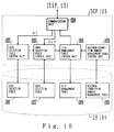
- Figure 10 shows the configuration of the SCP 103 and the DB 104.
- Figure 11 shows a data configuration of the number conversion service system based on the configuration of the fourth preferred embodiment shown in Figure 10.
- a call can be connected to a receiver's telephone number nearest to the sender's area in response to the sender's call.
- the DB 104 comprises a user selection table 1006, an area selection table 1007, a DN management table 1008, and a maximum connection number management table 1009.
- the communication unit 1001 transmits control information between the SSP 102 and the LS 101 ( Figure 1).
- the user selection table control unit 1002 reads user area information by accessing the user selection table 1006 in the DB 104 according to the registered receiver identification number UI received by the communication unit 1001, and it gives the information to the area selection table control unit 1003.
- the area selection table 1007 in the DB 104 is selected according to the user number selected from the user selection table 1006 by the user selection table control unit 1002. That is, the area selection table 1007 is provided for each user area corresponding to each user number.
- the area selection table 1007 stores a DN management table number corresponding to a sender's area identification number CLI.
- the information about the area where a user sends a call can be transmitted as a sender area dentification number CLI from the LS 101 ( Figure 1) for accommodating users.
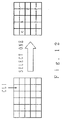
- the sender area identification number CLI is assigned to the LS 101 of each area after it is geographically divided, as shown by the left block in Figure 12.
- the divided areas are assigned group names A to F, for example, as shown by the right block in Figure 12.
- Each user is associated with a group, and a DN management table 1008 is assigned to each group.
- each user can connect a call to the receiver's telephone number nearest to the sender's area by registering to the DN management table 1008 corresponding to each group a receiver's telephone number near the area corresponding to the sender area identification number CLI related to the group.
- the area selection table 1007 performs the above described grouping for each sender area identification number CLI. That is, the area selection table 1007 assigns each sender area identification number CLI to a DN management table number corresponding to one of the groups A - F shown in Figure 12, for example.
- the area selection table control unit 1003 reads the information in the DN management table 1008 corresponding to the sender's area by accessing the area selection table 1007 in the DB 104 according to sender area identification number CLI received by the communication unit 1001, and it gives the information to the DN management table control unit 1008.
- a DN management table 1008 in the DB 104 is selected according to the DN management table number selected from the area selection table 1007 by the area selection table control unit 1003.
- the DN management table 1008 stores a plurality of directory numbers DN (telephone numbers to be converted) registered by each registered number conversion service user.
- DN telephone numbers to be converted
- idle/busy information indicating the idle/busy state of a terminal and the number of call connections made within a predetermined time period are added to each DN.
- the maximum number of connections is the same for all DNs and is selected from the maximum connection number management table 1009 by the maximum connection number management table control unit 1005. Then it is given to the DN management table control unit 1004.
- the configuration of the maximum connection number management table 1009 is shown in Figure 13.
- a plurality of patterns in pattern data PAT 1 - PAT 4, for example, are set in the maximum connection number management table 1009 with the maximum number of connections defined for each time period.
- pattern selection data groups for a specific date are assigned any of the above described pattern data for specific days such as national holidays.
- pattern selection data groups for each day of the week are assigned any of the above described pattern data for each day of the week.
- the maximum connection number management table control unit 1005 determines whether or not the present date is registered for pattern selection data for a specific day. If yes, the pattern for the date is read, and the maximum number of connections corresponding to the present time period is read from the pattern data corresponding to the pattern. This control unit reads the pattern corresponding to the present day of a week from the pattern selection data for each day of the week if the present date is not registered for pattern selection data for a specific day. Then, the above described control unit notifies the DN management table control unit 1004 of the maximum number of connections read as described above.
- the DN management table control unit 1004 accesses the DN management table 405 in the DB 104 according to the DN management table number provided by the area selection table control unit 1003, and selects a telephone number to be switched indicating the idle information.
- the above described control unit reads from the DN management table 1008 the number of connections associated with the selected telephone number to be switched and subtracts the above described number of connections from the maximum number of connections informed by the maximum connection number management table control unit 1005 in order to obtain the number of idle connections of each telephone number to be switched.
- the above described control unit selects the telephone number currently having the largest number of idle connections, and notifies from the communication unit 1001 the LS 101 on the receiving side of the selected number through the SSP 102 (shown in Figure 1).
- STEP 1 Issuing a call
- a user (sender) A issues a call by dialing a service access code SAC of a number conversion service and a registered receiver identification number UI of a target receiver B.
- STEP 2 Accepting an issue of a call
- the LS 101 On detecting an issue of a call, the LS 101 relays issue-of-call information to the SSP 102 according to the common call procedure by interpreting the SAC. In this case, the LS 101 notifies the SSP 102 of the sender area identification number CLI exclusively assigned to the LS 101 together with the above described service access code SAC and the registered receiver identification number UI of a target receiver B.
- STEP 3 Inquiry about a number
- the SSP 102 On receiving the SAC + UI + CLI from the LS 101, the SSP 102 recognizes a number conversion service by interpreting the SAC, notifies using SAC + UI + CLI the number conversion service unit in the SCP 103 of a receiver inquiry request, and waits for a response.
- the SCP 103 On receiving the inquiry about a receiver, the SCP 103 selects a directory number DN (telephone number to be switched) according to the registered receiver identification number UI and the sender area identification number CLI. Then, it notifies the SSP 102 of the selected number as a receiver's telephone number.
- DN telephone number to be switched
- the SSP 102 relays a call from a sender A to the LS 101 for accommodating a receiving terminal. After converting a number, a call is normally processed in the LS 101 on the receiving side and received by a corresponding terminal C. If a call is received successfully, it is informed to the SCP 103 through the SSP 102, and then busy information is set at the corresponding address in the DN management table 1008 and the number of connections is updated.
- a disconnecting process is performed in the normal call control sequence.
- the SCP 103 accesses the DN management table 405 in the DB 104, and sets idle information at the corresponding address.
- a call can be received by the receiver's telephone number nearest to the sender's area, and the call charge can thus be reduced.
- the above described fourth preferred embodiment is configured such that the DN management table 1008 can be selected from the area selection table 1007 by the sender area identification number CLI from the LS 101. If the DN management table 1008 must be grouped in smaller segment units than in sender area identification number CLI units, the sender's telephone number should be notified to the SCP 103 from the LS 101 through the SSP 102. For example, telephone numbers can be grouped based on their 4 low order digits as shown by A, B, C, and D in Figure 15.
- the maximum number of connections which is common among directory numbers DN is set according to the date, the day of the week, and the time period.
- the maximum number of connections can be set for each directory number DN according to the date, the day of the week, and the time period.
- a different DN management table 1008 can be selected according to the date, the day of the week, and the time period.
- the above described first to fourth preferred embodiments enable a target receiver to receive a call in a telephone switching network by dialing a predetermined identification number of a registered receiver without directly dialing a telephone number of a target receiver.
- the present invention is not limited to this kind of network.
- the present invention can be widely applied to general communication networks such as facsimile communication networks, data communication networks using packet switching networks, communication networks for assigning taxis, etc., and driver service communication networks such as JEF.
Landscapes
- Engineering & Computer Science (AREA)
- Business, Economics & Management (AREA)
- Marketing (AREA)
- Signal Processing (AREA)
- Computer Networks & Wireless Communication (AREA)
- Telephonic Communication Services (AREA)
Applications Claiming Priority (2)
| Application Number | Priority Date | Filing Date | Title |
|---|---|---|---|
| JP3035831A JP2874119B2 (ja) | 1991-03-01 | 1991-03-01 | 複数端末への着信呼分散サービス方式 |
| JP35831/91 | 1991-03-01 |
Publications (3)
| Publication Number | Publication Date |
|---|---|
| EP0501513A2 true EP0501513A2 (de) | 1992-09-02 |
| EP0501513A3 EP0501513A3 (de) | 1994-03-23 |
| EP0501513B1 EP0501513B1 (de) | 1998-08-26 |
Family
ID=12452909
Family Applications (1)
| Application Number | Title | Priority Date | Filing Date |
|---|---|---|---|
| EP92103476A Expired - Lifetime EP0501513B1 (de) | 1991-03-01 | 1992-02-28 | Anrufverteilsystem für mehrere Endgeräte |
Country Status (6)
| Country | Link |
|---|---|
| US (1) | US5365582A (de) |
| EP (1) | EP0501513B1 (de) |
| JP (1) | JP2874119B2 (de) |
| AU (1) | AU656760B2 (de) |
| CA (1) | CA2062068C (de) |
| DE (1) | DE69226716T2 (de) |
Cited By (9)
| Publication number | Priority date | Publication date | Assignee | Title |
|---|---|---|---|---|
| EP0592963A3 (de) * | 1992-10-16 | 1994-08-03 | Nippon Telegraph & Telephone | |
| EP0647051A1 (de) * | 1993-09-30 | 1995-04-05 | AT&T Corp. | Telekommunikationsnetzwerk mit netzwerkweiten integrierter automatischer Anrufverteilung |
| US5572584A (en) * | 1993-04-02 | 1996-11-05 | Ntt Mobile Communications Network Inc. | Connection control method for personal communications |
| WO1997024889A1 (en) * | 1995-12-29 | 1997-07-10 | Mci Communications Corporation | Flexible direct and shared termination call processing |
| EP0715475A3 (de) * | 1994-11-30 | 1998-01-28 | AT&T Corp. | Anrufverarbeitungsverfahren in einer PCS-Umgebung |
| EP0715443A3 (de) * | 1994-11-30 | 1999-01-27 | AT&T Corp. | Fernsprechanrufverarbeitungstechnik |
| WO1999044373A1 (en) * | 1998-02-12 | 1999-09-02 | Helsingin Puhelin Oyj - Helsingfors Telefon Abp | Method of connecting calls |
| EP0814591A3 (de) * | 1996-06-20 | 2001-11-21 | Telia Ab | Telekommunikationsnetzwerk |
| WO2002019675A1 (en) * | 2000-08-22 | 2002-03-07 | Elisa Communications Oyj | Method and system for assisting a telephone exchange operator |
Families Citing this family (15)
| Publication number | Priority date | Publication date | Assignee | Title |
|---|---|---|---|---|
| DE59209259D1 (de) * | 1991-09-30 | 1998-05-07 | Siemens Ag | Verfahren für den Betrieb einer Programmgesteuerten Kommunikationsanlage, bei der eine Verbindungsanforderung gleichzeitig an mehrere Kommunikationsendgeräte signalisiert wird |
| US5649004A (en) * | 1992-04-28 | 1997-07-15 | Canon Kabushiki Kaisha | Private branch exchange |
| US5469500A (en) * | 1993-11-12 | 1995-11-21 | Voiceplex Corporation | Method and apparatus for delivering calling services |
| US5621729A (en) * | 1995-06-07 | 1997-04-15 | Geophonic Networks, Inc. | Receiver controlled communication system |
| US8041341B1 (en) | 1995-06-07 | 2011-10-18 | Single Touch Interactive, Inc. | System of providing information to a telephony subscriber |
| JP2798019B2 (ja) * | 1995-09-25 | 1998-09-17 | 日本電気株式会社 | 蓄積型データ通信端末 |
| JPH1013532A (ja) * | 1996-06-19 | 1998-01-16 | Fujitsu Ltd | インテリジェントネットワークにおける通信状態管理方式および方法 |
| US6771764B1 (en) * | 2000-01-26 | 2004-08-03 | Rockwell Electronic Commerce Corp. | Schedule based transaction routing |
| DE10108824A1 (de) * | 2001-02-23 | 2002-09-12 | Siemens Ag | Verfahren zum Betrieb eines privaten Telekommunikationsnetzes |
| US20050172029A1 (en) * | 2004-01-29 | 2005-08-04 | International Business Machines Corporation | Method and apparatus for managing a connection pool using heuristic information |
| US9998585B2 (en) * | 2005-10-05 | 2018-06-12 | SITO Mobile R&D IP, LLC | Content selection and delivery of complementary information |
| US7929544B2 (en) * | 2006-12-29 | 2011-04-19 | Alcatel-Lucent Usa Inc. | Method and apparatus for linking identification data to a call in a network |
| CA2678816C (en) * | 2007-02-20 | 2016-02-09 | Anthony G. Macaluso | Automatic provisioning of abbreviated dialing codes |
| WO2008119030A1 (en) * | 2007-03-27 | 2008-10-02 | Macaluso Anthony G | Pushing coupon values |
| CN109542816B (zh) * | 2018-10-29 | 2021-05-18 | 中国电子科技集团公司第二十九研究所 | 一种基于分布式系统的服务总线构造方法 |
Family Cites Families (18)
| Publication number | Priority date | Publication date | Assignee | Title |
|---|---|---|---|---|
| US4348554A (en) * | 1980-03-21 | 1982-09-07 | Bell Telephone Laboratories, Incorporated | Method of providing virtual private network telephone service |
| JPS5862961A (ja) * | 1981-10-09 | 1983-04-14 | Nec Corp | 特番交換方式 |
| JPS619066A (ja) * | 1984-06-25 | 1986-01-16 | Fujitsu Ltd | 着信グル−プ番号の登録・接続方式 |
| US4737983A (en) * | 1985-10-02 | 1988-04-12 | American Telephone And Telegraph Company Communications, Inc. | Automatic call distributor telephone service |
| JPS6295058A (ja) * | 1985-10-22 | 1987-05-01 | Nippon Telegr & Teleph Corp <Ntt> | 加入者状態識別方法 |
| JPS6359090A (ja) * | 1986-08-27 | 1988-03-14 | Nec Corp | 代表扱加入回線着信呼均等配分方式 |
| BE905426A (nl) * | 1986-09-12 | 1987-03-12 | Bell Telephone Mfg | Communicatiesysteem. |
| US4797915A (en) * | 1986-10-09 | 1989-01-10 | American Telephone And Telegraph Company | Communication system having automatic call route selection |
| US4878239A (en) * | 1987-08-10 | 1989-10-31 | The Telephone Connection | Anonymous interactive telephone system with expanded outward calling features |
| CA1310731C (en) * | 1988-04-30 | 1992-11-24 | Mamoru Higuchi | Exchange system having originating call restriction function |
| JPH0714230B2 (ja) * | 1988-05-19 | 1995-02-15 | 富士通株式会社 | 着信呼の分配制御方式 |
| JPH02288760A (ja) * | 1989-04-28 | 1990-11-28 | Nec Corp | マルチプロセッサ制御電子交換機における着信呼制御方式 |
| JPH033498A (ja) * | 1989-05-31 | 1991-01-09 | Takamisawa Denki Seisakusho:Kk | 構内交換装置におけるacd受付台制御方式 |
| JP2770430B2 (ja) * | 1989-06-23 | 1998-07-02 | 株式会社日立製作所 | 加入者状態管理機能付き交換システム |
| US4987587A (en) * | 1989-07-26 | 1991-01-22 | International Business Machines Corporation | Method and apparatus for providing 800 number service |
| US4953204A (en) * | 1989-10-17 | 1990-08-28 | At&T Bell Laboratories | Multilocation queuing for telephone calls |
| US5144653A (en) * | 1990-03-20 | 1992-09-01 | Kabushiki Kaisha Toshiba | Telephone system capable of automatically distributing terminating calls and method of performing communication within the telephone system |
| US5222120A (en) * | 1990-04-23 | 1993-06-22 | Mci Communications Corporation | Long distance telephone switching system with enhanced subscriber services |
-
1991
- 1991-03-01 JP JP3035831A patent/JP2874119B2/ja not_active Expired - Fee Related
-
1992
- 1992-02-28 EP EP92103476A patent/EP0501513B1/de not_active Expired - Lifetime
- 1992-02-28 DE DE69226716T patent/DE69226716T2/de not_active Expired - Fee Related
- 1992-02-28 CA CA002062068A patent/CA2062068C/en not_active Expired - Fee Related
- 1992-03-02 US US07/844,538 patent/US5365582A/en not_active Expired - Fee Related
- 1992-03-02 AU AU11369/92A patent/AU656760B2/en not_active Ceased
Cited By (13)
| Publication number | Priority date | Publication date | Assignee | Title |
|---|---|---|---|---|
| US5703941A (en) * | 1992-10-16 | 1997-12-30 | Ntt Mobile Communications Network, Inc. | Connection control method for personal communications |
| EP0592963A3 (de) * | 1992-10-16 | 1994-08-03 | Nippon Telegraph & Telephone | |
| US5572584A (en) * | 1993-04-02 | 1996-11-05 | Ntt Mobile Communications Network Inc. | Connection control method for personal communications |
| EP0647051A1 (de) * | 1993-09-30 | 1995-04-05 | AT&T Corp. | Telekommunikationsnetzwerk mit netzwerkweiten integrierter automatischer Anrufverteilung |
| US5633924A (en) * | 1993-09-30 | 1997-05-27 | Lucent Technologies Inc. | Telecommunication network with integrated network-wide automatic call distribution |
| EP0715475A3 (de) * | 1994-11-30 | 1998-01-28 | AT&T Corp. | Anrufverarbeitungsverfahren in einer PCS-Umgebung |
| EP0715443A3 (de) * | 1994-11-30 | 1999-01-27 | AT&T Corp. | Fernsprechanrufverarbeitungstechnik |
| WO1997024889A1 (en) * | 1995-12-29 | 1997-07-10 | Mci Communications Corporation | Flexible direct and shared termination call processing |
| US5757903A (en) * | 1995-12-29 | 1998-05-26 | Mci Corporation | Flexible direct and shared termination call processing |
| EP0814591A3 (de) * | 1996-06-20 | 2001-11-21 | Telia Ab | Telekommunikationsnetzwerk |
| WO1999044373A1 (en) * | 1998-02-12 | 1999-09-02 | Helsingin Puhelin Oyj - Helsingfors Telefon Abp | Method of connecting calls |
| US6671366B1 (en) | 1998-02-12 | 2003-12-30 | Helsingin Puhelin Oyj-Helsingfors Telefon Abp | Method of connecting calls |
| WO2002019675A1 (en) * | 2000-08-22 | 2002-03-07 | Elisa Communications Oyj | Method and system for assisting a telephone exchange operator |
Also Published As
| Publication number | Publication date |
|---|---|
| JP2874119B2 (ja) | 1999-03-24 |
| EP0501513B1 (de) | 1998-08-26 |
| CA2062068A1 (en) | 1992-09-02 |
| JPH04274653A (ja) | 1992-09-30 |
| EP0501513A3 (de) | 1994-03-23 |
| DE69226716T2 (de) | 1999-02-11 |
| AU1136992A (en) | 1992-09-03 |
| US5365582A (en) | 1994-11-15 |
| CA2062068C (en) | 1995-10-17 |
| DE69226716D1 (de) | 1998-10-01 |
| AU656760B2 (en) | 1995-02-16 |
Similar Documents
| Publication | Publication Date | Title |
|---|---|---|
| US5365582A (en) | Call distributing service system for a plurality of terminals | |
| CA1296414C (en) | Inter-exchange carrier access selection feature for a pbx user | |
| US6078652A (en) | Least cost routing system | |
| US5337352A (en) | Private branch exchange system having an automatic optimal route selecting mechanism | |
| US5099511A (en) | Exchange system for incoming calls from direct-in lines | |
| US5475744A (en) | Private branch exchange capable of adding a calling station ID number to the call signal | |
| JPH0442651A (ja) | 構内電子交換機 | |
| US6466661B2 (en) | Method of establishing a connection, as well as exchange, service computer and communications network | |
| US7127052B1 (en) | Implementation of additional functions for user connections having individually configured performance criteria | |
| EP0649265A1 (de) | Fernsprechanrufverarbeitungssystem | |
| JPH11220555A (ja) | 無料通信接続の確立方法、並びにサービスユニット、交換機及び通信ネットワーク | |
| US6704408B2 (en) | Method and system for connecting a wireline telephone to a wireline switch in a wireline telecommunications network | |
| US6381326B1 (en) | System for handling large blocks of special number calls in a telecommunications network | |
| EP0531268A2 (de) | Büro-Kommunikationsrufnummer | |
| JP3408274B2 (ja) | 構内交換機 | |
| JPH0683499B2 (ja) | 電子式構内交換機の制御方式 | |
| JPH01128658A (ja) | 交換機の回線選択方式 | |
| JPH09130476A (ja) | 複数端末利用者への接続処理方法とその装置 | |
| JP3033668B2 (ja) | 交換機又はボタン電話機のisdnマルチライン回線における発着信方法 | |
| JP3023212B2 (ja) | 電子交換システム | |
| JP2002314721A (ja) | 低額通信接続システム,低額通信接続方法,通信接続プログラムおよびそのプログラム記録媒体 | |
| JPH01190064A (ja) | 構内交換機 | |
| JP2891826B2 (ja) | 回線選択方式 | |
| JP3288090B2 (ja) | 電子式構内交換システム | |
| JPH08195813A (ja) | 仮想専用網の無ダイヤル接続方法及び装置 |
Legal Events
| Date | Code | Title | Description |
|---|---|---|---|
| PUAI | Public reference made under article 153(3) epc to a published international application that has entered the european phase |
Free format text: ORIGINAL CODE: 0009012 |
|
| AK | Designated contracting states |
Kind code of ref document: A2 Designated state(s): DE FR GB |
|
| PUAL | Search report despatched |
Free format text: ORIGINAL CODE: 0009013 |
|
| AK | Designated contracting states |
Kind code of ref document: A3 Designated state(s): DE FR GB |
|
| 17P | Request for examination filed |
Effective date: 19940818 |
|
| 17Q | First examination report despatched |
Effective date: 19970206 |
|
| GRAG | Despatch of communication of intention to grant |
Free format text: ORIGINAL CODE: EPIDOS AGRA |
|
| GRAG | Despatch of communication of intention to grant |
Free format text: ORIGINAL CODE: EPIDOS AGRA |
|
| GRAH | Despatch of communication of intention to grant a patent |
Free format text: ORIGINAL CODE: EPIDOS IGRA |
|
| GRAH | Despatch of communication of intention to grant a patent |
Free format text: ORIGINAL CODE: EPIDOS IGRA |
|
| GRAA | (expected) grant |
Free format text: ORIGINAL CODE: 0009210 |
|
| AK | Designated contracting states |
Kind code of ref document: B1 Designated state(s): DE FR GB |
|
| REF | Corresponds to: |
Ref document number: 69226716 Country of ref document: DE Date of ref document: 19981001 |
|
| ET | Fr: translation filed | ||
| PG25 | Lapsed in a contracting state [announced via postgrant information from national office to epo] |
Ref country code: GB Free format text: LAPSE BECAUSE OF NON-PAYMENT OF DUE FEES Effective date: 19990228 |
|
| PLBE | No opposition filed within time limit |
Free format text: ORIGINAL CODE: 0009261 |
|
| STAA | Information on the status of an ep patent application or granted ep patent |
Free format text: STATUS: NO OPPOSITION FILED WITHIN TIME LIMIT |
|
| 26N | No opposition filed | ||
| GBPC | Gb: european patent ceased through non-payment of renewal fee |
Effective date: 19990228 |
|
| PG25 | Lapsed in a contracting state [announced via postgrant information from national office to epo] |
Ref country code: DE Free format text: LAPSE BECAUSE OF NON-PAYMENT OF DUE FEES Effective date: 19991201 |
|
| PGFP | Annual fee paid to national office [announced via postgrant information from national office to epo] |
Ref country code: FR Payment date: 20060220 Year of fee payment: 15 |
|
| REG | Reference to a national code |
Ref country code: FR Ref legal event code: ST Effective date: 20071030 |
|
| PG25 | Lapsed in a contracting state [announced via postgrant information from national office to epo] |
Ref country code: FR Free format text: LAPSE BECAUSE OF NON-PAYMENT OF DUE FEES Effective date: 20070228 |