EP0501548A1 - Verfahren zur Herstellung von Eisenfolie durch Elektrobeschichtung - Google Patents
Verfahren zur Herstellung von Eisenfolie durch Elektrobeschichtung Download PDFInfo
- Publication number
- EP0501548A1 EP0501548A1 EP92200363A EP92200363A EP0501548A1 EP 0501548 A1 EP0501548 A1 EP 0501548A1 EP 92200363 A EP92200363 A EP 92200363A EP 92200363 A EP92200363 A EP 92200363A EP 0501548 A1 EP0501548 A1 EP 0501548A1
- Authority
- EP
- European Patent Office
- Prior art keywords
- anode
- reaction
- electrolyte
- iron
- foil
- Prior art date
- Legal status (The legal status is an assumption and is not a legal conclusion. Google has not performed a legal analysis and makes no representation as to the accuracy of the status listed.)
- Ceased
Links
Images
Classifications
-
- C—CHEMISTRY; METALLURGY
- C25—ELECTROLYTIC OR ELECTROPHORETIC PROCESSES; APPARATUS THEREFOR
- C25D—PROCESSES FOR THE ELECTROLYTIC OR ELECTROPHORETIC PRODUCTION OF COATINGS; ELECTROFORMING; APPARATUS THEREFOR
- C25D1/00—Electroforming
- C25D1/04—Wires; Strips; Foils
Definitions
- the invention relates to a method of making iron foil by electrodeposition, wherein in an electrochemical cell having a non-soluble anode iron is deposited from an acid electrolyte onto a moving cathode, and the iron deposited onto the cathode is removed in the form of a foil.
- Belgian patent BE 8700832 describes use of two levels of temperature, namely a high temperature of approximately 100°C for the electrodeposition in the case of an electrolyte based on iron chloride, and a low temperature for the regeneration of the electrolyte. This suppresses reaction (III).
- the problem with this process is that before regeneration the electrolyte has to be cooled and then after regeneration re-heated. This takes a great deal of energy which is not acceptable for a product whose cost price already consists for a large part of energy costs.
- JP-A-61-111159 and JP-A-61-111160 as well as BE 8700832 mentioned above propose adding an organic substance to the electrolyte, the effect of which is likewise suppression of reaction (III).
- the object of the invention is to provide an improved method for manufacturing iron foil by means of electrodeposition which at least partly solves the above-mentioned problems.
- a method of making iron foil by electrodeposition wherein, in an electrochemical cell having an insoluble anode, iron is deposited from an acid electrolyte onto a moving cathode by the reaction: Fe2+ + 2e ⁇ ⁇ Fe (foil) (I), the iron foil so made is removed from the cathode and in a regenerator iron is dissolved into the electrolyte, wherein (i) hydrogen in the form of hydrogen gas or a gas containing hydrogen is supplied to the anode, the anode being such that the anode reaction: H2 ⁇ 2H+ + 2e ⁇ (II) takes place, said reaction (II) predominating at the anode over the reaction: 2Fe2+ ⁇ 2Fe3+ + 2e ⁇ (IV), and (ii) the dissolution of iron in the regenerator takes place at least partly by the reaction: Fe + 2H+ ⁇ Fe2+ + H2 (III).
- the rate of reaction (II) at the anode is at least three times the rate of reaction (IV), and if feasible reaction (IV) is wholly suppressed.
- reaction (IV) in which Fe3+ forms, does not occur or is minor.
- reaction (V) and (VI) can no longer occur and the reaction (V) is essentially replaced by reaction (III).
- reaction (III) which was regarded as undesirable in the prior art is the reaction occurring in the regenerator.
- iron for example in the form of scrap, can be dissolved and fully or almost fully converted into the form of the product iron foil.
- the hydrogen gas formed in the regenerator is collected and then supplied to the anode for reaction (III).
- the anode has a catalyst for reaction (II).
- the anode suitable for causing reaction (II) it is preferable that the anode is a porous anode carrying a catalyst and has means for feeding the hydrogen gas or gas containing hydrogen to a face of said anode directed away from said cathode, so that the gas contacts the electrolyte in pores of said anode and at the boundary of the gas, the electrolyte and the anode the reaction (II) takes place under the influence of the catalyst.
- Such an anode is known as a gas diffusion anode. It is noted that in Dutch patent application NL-A-8801511 it is already proposed to use a so-called gas diffusion anode in an electrodeposition process. This prior art proposal is concerned with suppression of reaction 2H2O ⁇ 4H+ + 4e ⁇ + O2 (VII) occurring at the insoluble anode during tinplating in order to improve the limited service life of the insoluble anode which was shortened as a result of corrosion by the oxygen formed. However, the present invention concerns suppression of reaction (IV) at the anode.
- the concentration of Fe3+ ions in the electrolyte is less than 1 kg/m3, and more preferably less than 0.2 kg/m3. At that concentration it is certain that Fe(OH)3 will not deposit.
- the pH of the electrolyte is less than 2. This gives the electrolyte high conductivity. However, in practice it may be preferable to maintain the pH not lower than 1, because of corrosion of installation parts.
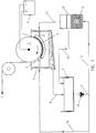
- Fig. 1 shows an iron foil 1 being manufactured in an electrochemical cell 2 comprising a rotating roller 3 and an anode 4.
- the anode 4 shown in Fig. 1 is a radial type anode but it may also be flat.
- the roller 3 and the anode 4 are connected to the negative and positive poles respectively of a voltage supply 5. This permits the roller to function as cathode in the electrochemical cell 2.
- Electrolyte is supplied at 6 at the gap between cathode roller 3 and anode 4 and flows along the gap. The whole assembly is placed in a tank 7. On the cathode roller 3 according to reaction (I) iron is deposited out from the electrolyte. The iron is removed from the cathode in the form of the foil 1.
- the consumed and Fe-ion impoverished electrolyte is collected at the bottom of the tank 7 and taken by means of a pipe 8 to a circulation tank 9.
- the electrolyte is conveyed by a pump 10 through pipes 11 and 12 to a regenerator 13 where scrap 14 dissolves and enriches the electrolyte with iron ions according to reaction (III).
- the electrolyte thus enriched is returned to the electrochemical cell by means of a pipe 15, the circulation tank 9 and pipes 11 and 16.
- the hydrogen gas formed and collected according to reaction (III) in the regenerator 13 is conveyed, optionally after scrubbing, by means of a pipe 17 to the anode 4 and to that side of anode 4 facing away from the cathode 3 for consumption in the reaction (II).
- the anode 4 used in the apparatus is a hydrogen gas diffusion anode which is described below.
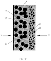
- Fig. 2 shows the principle of the hydrogen gas diffusion anode.
- the anode 4 has a hydrophobic part 18 where the gas containing hydrogen is taken to the anode on the side of the anode facing away from the cathode. This part has coarse pores.
- the hydrophobic part consists of active carbon 19 held in a Teflon matrix 20 and the hydrophobic part is provided with a layer of Carbon Felt 21 Torag paper to help support the electrode and to help conductivity.
- the anode 4 has on the electrolyte side, a hydrophilic part 22 with fine pores and a catalyst on the electrolyte side.
- the hydrophilic part consists of active carbon 23 loaded with platinum 24 as catalyst, in a Teflon matrix and is 70 to 120 ⁇ m thick.
- the reaction (II) takes place in the fine pores at the three-way boundary surface of the gas containing hydrogen, electrolyte and active carbon 23. Under the influence of the catalyst 24, H+ ions form at this boundary surface.
- the gas containing hydrogen may be a mixture of hydrogen with one or more other gases or a compound of hydrogen such as natural gas, for example. However, preference is given to a gas containing hydrogen that consists essentially of hydrogen.
- iron foil is manufactured using an apparatus such as shown in Figs. 1 and 2.
- an iron foil with a thickness of 20 ⁇ m is produced.
- the concentrations of the ions are: Fe2+ 250 g/l Fe3+ 3 g/l Cl ⁇ 300-350 g/l
- the hydrogen consumption is about 3.6 kg per hour.
- the temperature is 105°C, the current density 200 a?dm2, the anode/cathode spacing 2 mm.
- the electrolyte velocity in the anode/cathode gap is 4 m/s.
- the voltage drop across the cell is 2.6 V.
- the ratio of the rate of reaction (II) to the rate of reaction (IV) is 10:1.
- the anode consists of porous graphite and the catalyst on it is Pt. Fe is supplied into the regenerator. After a scrubbing process, the hydrogen gas released in the regenerator is supplied to the anode.
- Similar processes have been successfully performed over a current density range from 100 to 200 A/dm2 and an applied voltage range from 1 to 6 V.
- the anode/cathode spacing is preferably 1 to 3 mm.
- the maximum production capacity is approximately 94 kg/hour, being limited by the capacity of the current rectifier used which is approximately 90kA.
- the thicknesses of the iron foil obtained lie typically in the range 10 to 60 ⁇ m.
Landscapes
- Chemical & Material Sciences (AREA)
- Engineering & Computer Science (AREA)
- Chemical Kinetics & Catalysis (AREA)
- Electrochemistry (AREA)
- Materials Engineering (AREA)
- Metallurgy (AREA)
- Organic Chemistry (AREA)
- Electrolytic Production Of Metals (AREA)
Applications Claiming Priority (2)
| Application Number | Priority Date | Filing Date | Title |
|---|---|---|---|
| NL9100352 | 1991-02-27 | ||
| NL9100352A NL9100352A (nl) | 1991-02-27 | 1991-02-27 | Werkwijze voor het vervaardigen van ijzerfolie door elektrodepositie. |
Publications (1)
| Publication Number | Publication Date |
|---|---|
| EP0501548A1 true EP0501548A1 (de) | 1992-09-02 |
Family
ID=19858943
Family Applications (1)
| Application Number | Title | Priority Date | Filing Date |
|---|---|---|---|
| EP92200363A Ceased EP0501548A1 (de) | 1991-02-27 | 1992-02-10 | Verfahren zur Herstellung von Eisenfolie durch Elektrobeschichtung |
Country Status (6)
| Country | Link |
|---|---|
| US (1) | US5173168A (de) |
| EP (1) | EP0501548A1 (de) |
| JP (1) | JPH0578880A (de) |
| KR (1) | KR920016615A (de) |
| CA (1) | CA2061081A1 (de) |
| NL (1) | NL9100352A (de) |
Families Citing this family (10)
| Publication number | Priority date | Publication date | Assignee | Title |
|---|---|---|---|---|
| WO1996007124A1 (en) * | 1994-08-30 | 1996-03-07 | Phoenix Precision Graphics, Inc. | Purification system with sequential electrophoretic and particulate filter purifiers |
| US5942095A (en) * | 1996-10-07 | 1999-08-24 | Phoenix Precision Graphics, Inc. | Method of continuous purification of liquid toner in an electrostatic printing system |
| US7156972B2 (en) * | 2003-04-30 | 2007-01-02 | Hitachi Global Storage Technologies Netherlands B.V. | Method for controlling the ferric ion content of a plating bath containing iron |
| CA2576752A1 (en) * | 2007-02-02 | 2008-08-02 | Hydro-Quebec | Amorpheous fe100-a-bpamb foil, method for its preparation and use |
| US10465307B2 (en) | 2015-11-19 | 2019-11-05 | Fabric8Labs, Inc. | Apparatus for electrochemical additive manufacturing |
| CN109790215B (zh) | 2016-09-29 | 2023-06-30 | 北京韩美药品有限公司 | 异源二聚体免疫球蛋白构建体和其制备方法 |
| JP7031810B2 (ja) | 2016-11-18 | 2022-03-08 | ベイジン・ハンミ・ファーマシューティカル・カンパニー・リミテッド | 抗pd-1/抗her2天然抗体構造形態のヘテロダイマー系二重特異性抗体及びその製造方法 |
| WO2019153200A1 (zh) | 2018-02-08 | 2019-08-15 | 北京韩美药品有限公司 | 抗pd-1/抗her2天然抗体结构样异源二聚体形式双特异抗体及其制备 |
| EP4183905A4 (de) * | 2020-07-16 | 2024-10-23 | Toyo Kohan Co., Ltd. | Elektrolytische eisenfolie |
| JP7590616B1 (ja) * | 2024-07-25 | 2024-11-26 | 東邦亜鉛株式会社 | 電解鉄箔の製造方法 |
Citations (1)
| Publication number | Priority date | Publication date | Assignee | Title |
|---|---|---|---|---|
| EP0346981A1 (de) * | 1988-06-14 | 1989-12-20 | Hoogovens Groep B.V. | Verfahren zur elektrolytischen Metallbeschichtung eines Metallsubstrates in Form eines Streifens und Vorrichtung dazu |
Family Cites Families (5)
| Publication number | Priority date | Publication date | Assignee | Title |
|---|---|---|---|---|
| US3793165A (en) * | 1971-12-27 | 1974-02-19 | Prototech Co | Method of electrodeposition using catalyzed hydrogen |
| JPS6028913A (ja) * | 1983-07-26 | 1985-02-14 | Hoou Kk | 染毛剤 |
| JPH0713312B2 (ja) * | 1987-03-12 | 1995-02-15 | 田中貴金属工業株式会社 | 亜鉛の電解方法及び装置 |
| EP0281531A1 (de) * | 1987-03-04 | 1988-09-07 | Tanaka Kikinzoku Kogyo K.K. | Verfahren und Vorrichtung zur elektrolytischen Abscheidung von Zink |
| US5082538A (en) * | 1991-01-09 | 1992-01-21 | Eltech Systems Corporation | Process for replenishing metals in aqueous electrolyte solutions |
-
1991
- 1991-02-27 NL NL9100352A patent/NL9100352A/nl not_active Application Discontinuation
-
1992
- 1992-02-10 EP EP92200363A patent/EP0501548A1/de not_active Ceased
- 1992-02-10 US US07/832,890 patent/US5173168A/en not_active Expired - Fee Related
- 1992-02-12 CA CA002061081A patent/CA2061081A1/en not_active Abandoned
- 1992-02-25 JP JP4073239A patent/JPH0578880A/ja active Pending
- 1992-02-27 KR KR1019920003140A patent/KR920016615A/ko not_active Ceased
Patent Citations (1)
| Publication number | Priority date | Publication date | Assignee | Title |
|---|---|---|---|---|
| EP0346981A1 (de) * | 1988-06-14 | 1989-12-20 | Hoogovens Groep B.V. | Verfahren zur elektrolytischen Metallbeschichtung eines Metallsubstrates in Form eines Streifens und Vorrichtung dazu |
Non-Patent Citations (1)
| Title |
|---|
| PATENT ABSTRACTS OF JAPAN vol. 13, no. 21 (C-560)(3369) 18 January 1989 & JP-A-63 223 192 ( TANAKA KIKINZOKU KOGYO KK ) 16 September 1988 * |
Also Published As
| Publication number | Publication date |
|---|---|
| US5173168A (en) | 1992-12-22 |
| JPH0578880A (ja) | 1993-03-30 |
| KR920016615A (ko) | 1992-09-25 |
| CA2061081A1 (en) | 1992-08-28 |
| NL9100352A (nl) | 1992-09-16 |
Similar Documents
| Publication | Publication Date | Title |
|---|---|---|
| KR100954069B1 (ko) | 금속의 애노드 용해에 의한 농축조, 이를 포함하는 금속의 전기도금 장치 및 이를 사용한 전기도금 방법 | |
| EP0268823B1 (de) | Verfahren zur galvanischen Verzinnung mit einer unlöslichen Anode | |
| Lanza et al. | Removal of Zn (II) from chloride medium using a porous electrode: current penetration within the cathode | |
| CA1256819A (en) | Process for reconditioning a used ammoniacal copper etching solution containing copper solute | |
| EP0501548A1 (de) | Verfahren zur Herstellung von Eisenfolie durch Elektrobeschichtung | |
| EP0494434A2 (de) | Verfahren zur Metallauffrischung in wässrigen Elektrolytlösungen | |
| US4058441A (en) | Process for the regeneration of spent pickling solutions | |
| EP0346981B1 (de) | Verfahren zur elektrolytischen Metallbeschichtung eines Metallsubstrates in Form eines Streifens und Vorrichtung dazu | |
| RU2181150C2 (ru) | Способ травления стали | |
| EP0210769A1 (de) | Entfernung von Arsen aus Säuren | |
| US4906340A (en) | Process for electroplating metals | |
| US5639360A (en) | Electrode for an electrolytic cell, use thereof and method using same | |
| WO1999010564A3 (de) | Verfahren und vorrichtung zur konzentrationsregulierung von stoffen in elektrolyten | |
| US5198095A (en) | Method for continuously manganese-electroplating or manganese-alloy-electroplating steel sheet | |
| Adams et al. | Electrochemical oxidation of ferrous iron in very dilute solutions | |
| USRE34191E (en) | Process for electroplating metals | |
| CA1069459A (en) | Method of producing metal strip having a galvanized coating on one side | |
| EP0501547B1 (de) | Verfahren zur Elektroplattierung eines Stahlblechs mit einer zumindest teilweise aus Zink bestehenden Metallschicht | |
| Adaikkalam et al. | The electrochemical recycling of printed-wiring-board etchants | |
| JPS6340868B2 (de) | ||
| EP0550002A1 (de) | Verfahren zur galvanischen Verzinnung | |
| Expósito et al. | Use of a hydrogen‐diffusion electrode in the electrochemical removal of lead from effluents of lead electrowinning processes | |
| Njau et al. | Electrochemical reduction of nickel ions from diluteartificial solutions in a GBC reactor | |
| US4367128A (en) | Energy efficient self-regulating process for winning copper from aqueous solutions | |
| KR100297955B1 (ko) | 폐산염화제이구리부식제를재생시키는장치및방법 |
Legal Events
| Date | Code | Title | Description |
|---|---|---|---|
| PUAI | Public reference made under article 153(3) epc to a published international application that has entered the european phase |
Free format text: ORIGINAL CODE: 0009012 |
|
| 17P | Request for examination filed |
Effective date: 19920210 |
|
| AK | Designated contracting states |
Kind code of ref document: A1 Designated state(s): BE DE ES FR GB IT LU NL SE |
|
| 17Q | First examination report despatched |
Effective date: 19940909 |
|
| STAA | Information on the status of an ep patent application or granted ep patent |
Free format text: STATUS: THE APPLICATION HAS BEEN REFUSED |
|
| 18R | Application refused |
Effective date: 19950303 |