EP2311119B1 - Collecteur intégré - Google Patents
Collecteur intégré Download PDFInfo
- Publication number
- EP2311119B1 EP2311119B1 EP09807764.7A EP09807764A EP2311119B1 EP 2311119 B1 EP2311119 B1 EP 2311119B1 EP 09807764 A EP09807764 A EP 09807764A EP 2311119 B1 EP2311119 B1 EP 2311119B1
- Authority
- EP
- European Patent Office
- Prior art keywords
- manifold
- pins
- cavity
- cell stack
- mould cavity
- Prior art date
- Legal status (The legal status is an assumption and is not a legal conclusion. Google has not performed a legal analysis and makes no representation as to the accuracy of the status listed.)
- Active
Links
Images


Classifications
-
- H—ELECTRICITY
- H01—ELECTRIC ELEMENTS
- H01M—PROCESSES OR MEANS, e.g. BATTERIES, FOR THE DIRECT CONVERSION OF CHEMICAL ENERGY INTO ELECTRICAL ENERGY
- H01M10/00—Secondary cells; Manufacture thereof
- H01M10/36—Accumulators not provided for in groups H01M10/05-H01M10/34
- H01M10/365—Zinc-halogen accumulators
-
- B—PERFORMING OPERATIONS; TRANSPORTING
- B29—WORKING OF PLASTICS; WORKING OF SUBSTANCES IN A PLASTIC STATE IN GENERAL
- B29C—SHAPING OR JOINING OF PLASTICS; SHAPING OF MATERIAL IN A PLASTIC STATE, NOT OTHERWISE PROVIDED FOR; AFTER-TREATMENT OF THE SHAPED PRODUCTS, e.g. REPAIRING
- B29C33/00—Moulds or cores; Details thereof or accessories therefor
- B29C33/76—Cores
-
- B—PERFORMING OPERATIONS; TRANSPORTING
- B29—WORKING OF PLASTICS; WORKING OF SUBSTANCES IN A PLASTIC STATE IN GENERAL
- B29C—SHAPING OR JOINING OF PLASTICS; SHAPING OF MATERIAL IN A PLASTIC STATE, NOT OTHERWISE PROVIDED FOR; AFTER-TREATMENT OF THE SHAPED PRODUCTS, e.g. REPAIRING
- B29C45/00—Injection moulding, i.e. forcing the required volume of moulding material through a nozzle into a closed mould; Apparatus therefor
- B29C45/17—Component parts, details or accessories; Auxiliary operations
- B29C45/26—Moulds
- B29C45/2628—Moulds with mould parts forming holes in or through the moulded article, e.g. for bearing cages
-
- H—ELECTRICITY
- H01—ELECTRIC ELEMENTS
- H01M—PROCESSES OR MEANS, e.g. BATTERIES, FOR THE DIRECT CONVERSION OF CHEMICAL ENERGY INTO ELECTRICAL ENERGY
- H01M12/00—Hybrid cells; Manufacture thereof
- H01M12/08—Hybrid cells; Manufacture thereof composed of a half-cell of a fuel-cell type and a half-cell of the secondary-cell type
- H01M12/085—Zinc-halogen cells or batteries
-
- H—ELECTRICITY
- H01—ELECTRIC ELEMENTS
- H01M—PROCESSES OR MEANS, e.g. BATTERIES, FOR THE DIRECT CONVERSION OF CHEMICAL ENERGY INTO ELECTRICAL ENERGY
- H01M8/00—Fuel cells; Manufacture thereof
- H01M8/02—Details
- H01M8/0271—Sealing or supporting means around electrodes, matrices or membranes
-
- H—ELECTRICITY
- H01—ELECTRIC ELEMENTS
- H01M—PROCESSES OR MEANS, e.g. BATTERIES, FOR THE DIRECT CONVERSION OF CHEMICAL ENERGY INTO ELECTRICAL ENERGY
- H01M8/00—Fuel cells; Manufacture thereof
- H01M8/24—Grouping of fuel cells, e.g. stacking of fuel cells
- H01M8/241—Grouping of fuel cells, e.g. stacking of fuel cells with solid or matrix-supported electrolytes
-
- H—ELECTRICITY
- H01—ELECTRIC ELEMENTS
- H01M—PROCESSES OR MEANS, e.g. BATTERIES, FOR THE DIRECT CONVERSION OF CHEMICAL ENERGY INTO ELECTRICAL ENERGY
- H01M8/00—Fuel cells; Manufacture thereof
- H01M8/24—Grouping of fuel cells, e.g. stacking of fuel cells
- H01M8/2465—Details of groupings of fuel cells
-
- H—ELECTRICITY
- H01—ELECTRIC ELEMENTS
- H01M—PROCESSES OR MEANS, e.g. BATTERIES, FOR THE DIRECT CONVERSION OF CHEMICAL ENERGY INTO ELECTRICAL ENERGY
- H01M8/00—Fuel cells; Manufacture thereof
- H01M8/24—Grouping of fuel cells, e.g. stacking of fuel cells
- H01M8/2465—Details of groupings of fuel cells
- H01M8/2484—Details of groupings of fuel cells characterised by external manifolds
-
- H—ELECTRICITY
- H01—ELECTRIC ELEMENTS
- H01M—PROCESSES OR MEANS, e.g. BATTERIES, FOR THE DIRECT CONVERSION OF CHEMICAL ENERGY INTO ELECTRICAL ENERGY
- H01M8/00—Fuel cells; Manufacture thereof
- H01M8/24—Grouping of fuel cells, e.g. stacking of fuel cells
- H01M8/2465—Details of groupings of fuel cells
- H01M8/2484—Details of groupings of fuel cells characterised by external manifolds
- H01M8/2485—Arrangements for sealing external manifolds; Arrangements for mounting external manifolds around a stack
-
- B—PERFORMING OPERATIONS; TRANSPORTING
- B29—WORKING OF PLASTICS; WORKING OF SUBSTANCES IN A PLASTIC STATE IN GENERAL
- B29C—SHAPING OR JOINING OF PLASTICS; SHAPING OF MATERIAL IN A PLASTIC STATE, NOT OTHERWISE PROVIDED FOR; AFTER-TREATMENT OF THE SHAPED PRODUCTS, e.g. REPAIRING
- B29C45/00—Injection moulding, i.e. forcing the required volume of moulding material through a nozzle into a closed mould; Apparatus therefor
- B29C45/17—Component parts, details or accessories; Auxiliary operations
- B29C45/40—Removing or ejecting moulded articles
- B29C45/44—Removing or ejecting moulded articles for undercut articles
-
- B—PERFORMING OPERATIONS; TRANSPORTING
- B29—WORKING OF PLASTICS; WORKING OF SUBSTANCES IN A PLASTIC STATE IN GENERAL
- B29L—INDEXING SCHEME ASSOCIATED WITH SUBCLASS B29C, RELATING TO PARTICULAR ARTICLES
- B29L2031/00—Other particular articles
- B29L2031/712—Containers; Packaging elements or accessories, Packages
- B29L2031/7146—Battery-cases
-
- Y—GENERAL TAGGING OF NEW TECHNOLOGICAL DEVELOPMENTS; GENERAL TAGGING OF CROSS-SECTIONAL TECHNOLOGIES SPANNING OVER SEVERAL SECTIONS OF THE IPC; TECHNICAL SUBJECTS COVERED BY FORMER USPC CROSS-REFERENCE ART COLLECTIONS [XRACs] AND DIGESTS
- Y02—TECHNOLOGIES OR APPLICATIONS FOR MITIGATION OR ADAPTATION AGAINST CLIMATE CHANGE
- Y02E—REDUCTION OF GREENHOUSE GAS [GHG] EMISSIONS, RELATED TO ENERGY GENERATION, TRANSMISSION OR DISTRIBUTION
- Y02E60/00—Enabling technologies; Technologies with a potential or indirect contribution to GHG emissions mitigation
- Y02E60/10—Energy storage using batteries
-
- Y—GENERAL TAGGING OF NEW TECHNOLOGICAL DEVELOPMENTS; GENERAL TAGGING OF CROSS-SECTIONAL TECHNOLOGIES SPANNING OVER SEVERAL SECTIONS OF THE IPC; TECHNICAL SUBJECTS COVERED BY FORMER USPC CROSS-REFERENCE ART COLLECTIONS [XRACs] AND DIGESTS
- Y02—TECHNOLOGIES OR APPLICATIONS FOR MITIGATION OR ADAPTATION AGAINST CLIMATE CHANGE
- Y02E—REDUCTION OF GREENHOUSE GAS [GHG] EMISSIONS, RELATED TO ENERGY GENERATION, TRANSMISSION OR DISTRIBUTION
- Y02E60/00—Enabling technologies; Technologies with a potential or indirect contribution to GHG emissions mitigation
- Y02E60/30—Hydrogen technology
- Y02E60/50—Fuel cells
Definitions
- the present invention relates to flowing electrolyte battery manifolds.
- the invention relates to a method of forming an integral manifold for a cell stack of a flowing electrolyte battery.
- Lead-acid batteries Batteries used in stand alone power supply systems are commonly lead-acid batteries.
- lead-acid batteries have limitations in terms of performance and environmental safety. Typical lead-acid batteries often have very short lifetimes in hot climate conditions, especially when they are occasionally fully discharged. Lead-acid batteries are also environmentally hazardous, since lead is a major component of lead-acid batteries and can cause serious environmental problems during manufacturing and disposal.
- Flowing electrolyte batteries such as zinc-bromine batteries, zinc-chlorine batteries, and vanadium flow batteries, offer a potential to overcome the above mentioned limitations of lead-acid batteries.
- the useful lifetime of flowing electrolyte batteries is not affected by deep discharge applications, and the energy to weight ratio of flowing electrolyte batteries is up to six times higher than that of lead-acid batteries.
- a flowing electrolyte battery like a lead acid battery, comprises a stack of cells to produce a certain voltage higher than that of individual cells. But unlike a lead acid battery, cells in a flowing electrolyte battery are hydraulically connected through an electrolyte circulation path. This can be problematic as shunt currents can flow through the electrolyte circulation path from one series-connected cell to another causing energy losses and imbalances in the individual charge states of the cells. To prevent or reduce such shunt currents, flowing electrolyte batteries define sufficiently long electrolyte circulation paths between cells, thereby increasing electrical resistance between cells.
- Electrolyte is commonly supplied to and discharged from a cell stack via external manifolds. Each cell has multiple inlets and outlets at capillary openings of the electrolyte circulation paths. Each external manifold is connected to the circulation paths of the cell stack using a delicate connection apparatus comprising an array of elastomer connection tubes. A typical 54-cell stack requires 216 elastomer connection tubes. Such a delicate connection apparatus is not only difficult to manufacture, but is also prone to damage during assembly and use.
- FIG. 1 a diagram illustrates a perspective view of a cell stack 10 for a flowing electrolyte battery, as known according to the prior art.
- Cells in the cell stack 10 are connected to external manifold bodies 12 via an array of elastomer connection tubes 14.
- US Patent No. 3,755,514 discloses a method of making primary metal-air batteries.
- the method includes positioning cells in a mould with removable pins being received in respective holes in the mould, and introducing a settable compound into the mould.
- the compound is then allowed to set so as to form a body extending between and joining adjacent cells, and the pins are removed so as to leave apertures in the body through which electrolyte can flow to the cell.
- an object of the present invention is to overcome or alleviate one or more limitations of the prior art including providing improved manifolds for flowing electrolyte batteries.
- a further object of the present invention is to provide a method of forming an integral manifold for a cell stack of an electrolyte battery.
- the invention resides in a method of forming passages of an integral manifold adjacent a cell stack of a flowing electrolyte battery, the method including:
- the method includes closing off parts of the passages which extend between the manifold cavity and an exterior of the moulded section.
- the capillary openings are defined at tube ends of capillary tubes which extend into the half cells.
- each pin in the plurality of pins has a head which is outside of the mould cavity as the material solidifies and an inner end which is received in one of the capillary openings.
- the head of each pin has a larger diameter than the inner end.
- the mould cavity is formed by formwork which is removed after the moulded section is formed.
- an extraction panel is used to remove the pins from the moulded section.
- the formwork has apertures defined therein, and each pin in the plurality of pins is located in an aperture when inserting each pin into the mould cavity.
- Embodiments of the present invention comprise a method of forming passages of an integral manifold adjacent a cell stack of a flowing electrolyte battery, and a flowing electrolyte battery having an integral manifold.
- adjectives such as first and second, left and right, front and back, top and bottom, etc., are used solely to define one element or method step from another element or method step without necessarily requiring a specific relative position or sequence that is described by the adjectives.
- Words such as “comprises” or “includes” are not used to define an exclusive set of elements or method steps. Rather, such words merely define a minimum set of elements or method steps included in a particular embodiment of the present invention.
- FIG. 1 A method of forming an integral manifold of a flowing electrolyte battery is described in sequence with reference to Figures 2, 3 and 5-8 of the drawings.
- the drawings show how an integral manifold is formed at only one corner of a cell stack of a flowing electrolyte battery. It must be appreciated that similar integral manifolds will be formed at all four corners of the cell stack or at other locations on the flowing electrolyte battery.
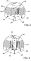
- FIG. 2 a diagram illustrates a perspective view of a corner of a cell stack 20 of a flowing electrolyte battery.
- the cell stack 20 is located on a bottom panel 22 of formwork.
- the bottom panel 22 has location holes 23 defined in its sides.
- the cell stack 20 comprises a stack of electrode plates 24 separated by separator plates 25 to define a plurality of half cells.
- the half cells are similar to the half cells described in the Applicant's co-pending International Patent Application No. PCT/AU2008/000353, filed 13 March 2008 , published as WO 2008/116248 .
- the half cells each comprise an electrode plate 24, an adjacent separator plate 25 and a capillary tube 26.
- the capillary tubes 26 are positioned in capillary tube channels formed between each electrode plate 24 and adjacent separator plate 25. As shown, the capillary tubes 26 extend slightly out from the edges of the electrode plates 24 and separator plates 25.
- the half cells are generally rectangular in top plan view, but have a cut-away region 28 at corners thereof.
- the capillary tubes 26 can be of polymeric material or any other material that is compatible for welding to injected plastic.
- the bottom panel 22 is part of a formwork which together defines a cavity adjacent the corner of the cell stack 20.
- the cavity will be described in more detail with reference to FIG. 5 of the drawings.
- a manifold plug 30 is located on the bottom panel 22.
- the manifold plug 30 is located in the cut-away region 28.
- the manifold plug 30 is generally cylindrical having a base 32 and an upper end 34.
- the base 32 is supported on the bottom panel 22.
- Two sets of staggered holes 36 are defined in the manifold plug 30. The holes 36 align with openings of the capillary tubes 26 of the cell stack 20.
- FIG. 4 shows pins 38 inserted into the holes 36 in the manifold plug 30.
- the pins 38 are inserted in the holes 36 in a configuration wherein the pins 38 pass through the manifold plug 30. Inner ends of the pins 38 are contiguous with the openings of the capillary tubes 26, thereby to close off the tubes 26.
- FIG.4 is illustrative of the arrangement of the pins 38 relative to the manifold plug 30 and the cell stack 20, but is not illustrative of a step in the method of forming the integral manifold.
- FIG. 5 shows a next step in the forming of an integral manifold.
- a top panel 40 of formwork is placed on top of the cell stack 20 and an end panel 42 of formwork closes an end of the cell stack 20.
- a mould cavity 44 is defined between the bottom panel 22, top panel 40, end panel 42 and a side panel 50 (which is indicated in FIG. 6 ).
- the end panel 42 has a set of staggered holes there through which align with the holes 36 in the manifold plug 30.
- the top panel 40 has a fill hole 48 that is open to the mould cavity 44. In use, heated mould material is injected into the mould cavity 44 via the fill hole 48.
- the heated mould material can be any polymeric material that effectively bonds with the electrode plates 24 and the capillary tubes 26.
- the heated mould material bonds to the exposed edges of the electrode plates 24 and forms a hermetic seal between the electrode plates 24. Further, the heated mould material bonds to and forms a hermetic seal around the circumference of the outer surface of each capillary tube 26 that extends out from the edges of the electrode plates 24.
- the top panel 40 further includes a hole 46 which aligns with the manifold plug 30, and in which the upper end 34 of the manifold plug 30 is received.
- the pins 38 are inserted into the mould cavity via the holes in the end panel 42.
- the pins 38 pass through the manifold plug 30 and inner ends of the pins 38 are received in the openings of the capillary tubes 26 as described above with reference to FIG. 4 .
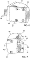
- FIGs. 6 and 7 show different diagrammatic perspective views of a corner of the cell stack 20 clad with formwork.
- the formwork includes the side panel 50, which has countersunk holes 52 there through which align with the location holes 23 in the top panel 40 and bottom panel 22.
- the side panel 50 is fastened in position by fasteners which extend through the countersunk holes 52 to engage the location holes 23.
- the pins 38 also extend through staggered holes in an extraction panel 43 that is located on the outside of the end panel 42.
- the mould cavity 44 is filled with mould material.
- mould material can be polyethylene, polypropylene, or another suitable material. The mould material is then allowed to set.
- the fasteners holding the formwork together are removed, and the pins 38 and the respective panels 22, 40, 42 and 50 are also removed.
- the pins 38 are removed by pulling the extraction panel 43 away from the end panel 42.
- the manifold plug 30 is also removed.
- the resulting moulded section 54 has passages 56 which extend between a manifold cavity 58, defined by the previous location of the manifold plug 30, and the capillary tubes 26. Passages 59 that lead from the outside of the moulded section 54 to the manifold cavity 58 are then plugged.
- An integral manifold of the flowing electrolyte battery thus comprises the manifold cavity 58 and the passages 56 formed in the moulded section 54.
- the passages 56 fluidly connect the manifold cavity 58 to the capillary tubes 26.
- a manifold cavity may be formed by omitting the manifold plug 30 from the mould cavity 44 when assembling the panels 22, 40, 42 and 50 to form a mould. After mould material has set inside the mould and the mould panels 22, 40, 42 and 50 are removed, a manifold cavity is formed by drilling a hole into the moulded section 54.
- side panels can be welded onto the sides of the cell stack 20, including onto the sides of the moulded section 54, to effectively seal the cell stack.
- Various welding techniques for attaching such side panels are known to those having ordinary skill in the art.
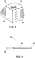
- a pin 38 has an inner end 60, a head 62, and a shank 64 that extends between the inner end 60 and the head 62.
- the inner end 60 is dimensioned to be received in an opening of a capillary tube 26, so as to seal the capillary tube 26 and prevent liquid mould material from blocking the opening of the capillary tube 26 when the mould cavity 44 is filled.
- the shank 64 is dimensioned to be received in a hole 36 in the manifold plug 30, so as to seal the manifold cavity 58 and prevent liquid mould material from entering the manifold cavity 58 when the mould cavity 44 is filled.
- a diameter of the head 62 is dimensioned to be larger than the holes in the extraction panel 43. As such, the pins 38 can be extracted from the mould cavity 44 by pulling the extraction panel 43 away from the end plate 42.
- the integral manifold formed in the manner described hereinabove is less prone to damage than prior art external manifolds, and provides an enhanced seal between the manifold and capillary tubes of a cell stack of a flowing electrolyte battery.
- a kit for forming the integral manifold comprises the manifold plug 30, the pins 38 and the panels 22, 40, 42 and 50.
Landscapes
- Engineering & Computer Science (AREA)
- Manufacturing & Machinery (AREA)
- Chemical Kinetics & Catalysis (AREA)
- General Chemical & Material Sciences (AREA)
- Electrochemistry (AREA)
- Chemical & Material Sciences (AREA)
- Sustainable Development (AREA)
- Sustainable Energy (AREA)
- Life Sciences & Earth Sciences (AREA)
- Mechanical Engineering (AREA)
- Fuel Cell (AREA)
- Hybrid Cells (AREA)
- Filling, Topping-Up Batteries (AREA)
Claims (8)
- Procédé destiné à former des passages d'un collecteur intégré à proximité d'un empilement de cellules (20) d'une batterie à flux d'électrolyte, le procédé consistant à :former une cavité de moule (44) à proximité de l'empilement de cellules, dans lequel la cavité de moule est exposée aux ouvertures capillaires (26) des cellules de l'empilement de cellules ;insérer un bouchon de collecteur (30) qui définit une cavité de collecteur (58) dans la cavité de moule ;placer une pluralité de broches (38) dans la cavité de moule, dans lequel les zones d'extrémité des broches sont contiguës aux ouvertures capillaires et les broches passent à travers le bouchon du collecteur ;remplir la cavité de moule de matériau ;permettre au matériau de se solidifier dans une section moulée (54) ;enlever les broches de la section moulée et du bouchon du collecteur ; etenlever le bouchon du collecteur (30) de la section moulée ;en vertu duquel des passages (56) sont formés dans la section moulée à proximité de la cavité du collecteur (58), passages qui sont en communication fluidique à la fois avec les ouvertures capillaires (26) et la cavité du collecteur.
- Procédé selon la revendication 1, comprenant la fermeture de parties des passages (59) qui s'étendent de la cavité du collecteur (58) à une partie extérieure de la section moulée (54) .
- Procédé selon la revendication 1, dans lequel les ouvertures capillaires (26) sont définies comme des extrémités de tubes des tubes capillaires qui s'étendent jusqu'aux demi-cellules.
- Procédé selon la revendication 1, dans lequel chaque broche appartenant à la pluralité de broches (38) est dotée d'une tête située en dehors de la cavité de moule (44), alors que le matériau se solidifie, et d'une extrémité intérieure que reçoit une des ouvertures capillaires.
- Procédé selon la revendication 4, dans lequel le diamètre de la tête de chaque broche (38) est supérieure à l'extrémité intérieure.
- Procédé selon la revendication 1, dans lequel la cavité de moule (44) est formée par coffrage que l'on enlève une fois la section moulée formée.
- Procédé selon la revendication 6, dans lequel le coffrage comprend des ouvertures qui y sont définies, et chaque broche appartenant à la pluralité de broches (38) est située dans une ouverture lors de l'insertion de chaque broche dans la cavité de moule.
- Procédé selon la revendication 1, dans lequel l'on utilise un panneau d'extraction (43) pour enlever les broches (38) de la section moulée.
Applications Claiming Priority (2)
| Application Number | Priority Date | Filing Date | Title |
|---|---|---|---|
| AU2008904314A AU2008904314A0 (en) | 2008-08-22 | Integral manifold | |
| PCT/AU2009/001078 WO2010020013A1 (fr) | 2008-08-22 | 2009-08-21 | Collecteur intégré |
Publications (3)
| Publication Number | Publication Date |
|---|---|
| EP2311119A1 EP2311119A1 (fr) | 2011-04-20 |
| EP2311119A4 EP2311119A4 (fr) | 2014-04-02 |
| EP2311119B1 true EP2311119B1 (fr) | 2018-02-21 |
Family
ID=41706774
Family Applications (1)
| Application Number | Title | Priority Date | Filing Date |
|---|---|---|---|
| EP09807764.7A Active EP2311119B1 (fr) | 2008-08-22 | 2009-08-21 | Collecteur intégré |
Country Status (7)
| Country | Link |
|---|---|
| US (1) | US9225042B2 (fr) |
| EP (1) | EP2311119B1 (fr) |
| JP (1) | JP5389920B2 (fr) |
| CN (1) | CN102124593B (fr) |
| AU (1) | AU2009284708B2 (fr) |
| MY (1) | MY156818A (fr) |
| WO (1) | WO2010020013A1 (fr) |
Families Citing this family (13)
| Publication number | Priority date | Publication date | Assignee | Title |
|---|---|---|---|---|
| US8591708B2 (en) * | 2008-06-12 | 2013-11-26 | Michael Jones | Electrolytic cell and related methods of making and use |
| EP2318570A4 (fr) * | 2008-06-12 | 2011-09-21 | Cell Inc The | Cellule électrolytique et procédés de fabrication et d utilisation s y rapportant |
| US8785023B2 (en) | 2008-07-07 | 2014-07-22 | Enervault Corparation | Cascade redox flow battery systems |
| US7820321B2 (en) | 2008-07-07 | 2010-10-26 | Enervault Corporation | Redox flow battery system for distributed energy storage |
| MY156818A (en) | 2008-08-22 | 2016-03-31 | Redflow R&D Pty Ltd | Integral manifold |
| US8980484B2 (en) | 2011-03-29 | 2015-03-17 | Enervault Corporation | Monitoring electrolyte concentrations in redox flow battery systems |
| US8916281B2 (en) | 2011-03-29 | 2014-12-23 | Enervault Corporation | Rebalancing electrolytes in redox flow battery systems |
| US9685651B2 (en) | 2012-09-05 | 2017-06-20 | Ess Tech, Inc. | Internally manifolded flow cell for an all-iron hybrid flow battery |
| US9614244B2 (en) | 2012-09-05 | 2017-04-04 | Ess Tech, Inc. | Redox and plating electrode systems for an all-iron hybrid flow battery |
| CN103094586A (zh) * | 2013-01-10 | 2013-05-08 | 王昕� | 液流电池的集成汇流管 |
| WO2015054721A1 (fr) * | 2013-10-15 | 2015-04-23 | Redflow R&D Pty Ltd | Plaque à électrode et procédés de fabrication et de test d'une plaque à électrode |
| GB2542324A (en) * | 2014-07-21 | 2017-03-15 | Redflow R&D Pty Ltd | A method of forming an integral manifold |
| KR101802749B1 (ko) * | 2016-10-20 | 2017-12-28 | 주식회사 에이치투 | 캐필러리 튜브를 포함한 흐름전지 스택 |
Family Cites Families (21)
| Publication number | Priority date | Publication date | Assignee | Title |
|---|---|---|---|---|
| GB1370290A (en) * | 1971-04-27 | 1974-10-16 | Lucas Industries Ltd | Primary metal-air batteries |
| IL57898A (en) * | 1979-07-26 | 1983-05-15 | Helioset Advanced Tech | Method for injection-molding of elements onto extruded units |
| US4464324A (en) * | 1981-09-21 | 1984-08-07 | Ozen | Apparatus and method for injection moulding of plastic parts of irregular shape, hollow or undercut form |
| DE3277276D1 (en) * | 1982-05-04 | 1987-10-15 | Meidensha Electric Mfg Co Ltd | Electrolytes circulation type cell stack secondary battery |
| FR2564773B1 (fr) | 1984-05-23 | 1987-02-13 | Ind Plastiques Moules | Moules monobloc pour le moulage par injection des matieres plastiques |
| JPH02142070A (ja) * | 1988-11-22 | 1990-05-31 | Toyota Motor Corp | 液循環式金属−ハロゲン電池 |
| US5034023A (en) * | 1989-12-21 | 1991-07-23 | Corning Incorporated | Ceramic honeycomb structures as oxygen separators or concentrators |
| US5188911A (en) * | 1991-02-25 | 1993-02-23 | Magnavox Electronic Systems Company | Tapered manifold for batteries requiring forced electrolyte flow |
| CA2118866A1 (fr) | 1993-06-21 | 1994-12-22 | Clarence A. Meadows | Boitier d'accumulateur a electrodes bipolaires et procede de fabrication |
| US5556582A (en) * | 1995-02-17 | 1996-09-17 | Stanford University | Injection molding gate flow control |
| US6309208B1 (en) * | 1997-06-13 | 2001-10-30 | Synventive Molding Solutions, Inc. | Apparatus for proportionally controlling fluid delivery to a mold |
| US6073536A (en) * | 1998-03-02 | 2000-06-13 | Campbell; A. Keith | Automotive hydraulic system and method for driving a hydraulic accessory in parallel with a power steering unit |
| AU2001292869A1 (en) | 2000-09-22 | 2002-04-02 | Powercell Corporation | Electrochemical cell with manifold device and associated method of manufacture and operation |
| US7175413B1 (en) * | 2002-09-23 | 2007-02-13 | Owens-Illinois Closure Inc. | Elastomeric dispensing valve manufacture |
| JP2004319341A (ja) | 2003-04-17 | 2004-11-11 | Sumitomo Electric Ind Ltd | レドックスフロー電池 |
| US7708923B1 (en) * | 2004-02-19 | 2010-05-04 | Saint-Gobain Performance Plastics Corporation | Process of molding a coupling for interconnecting tubes |
| JP5068052B2 (ja) * | 2006-09-29 | 2012-11-07 | 昭和電工株式会社 | 燃料電池用セパレータ、燃料電池用セルおよび燃料電池用セルユニット、ならびに燃料電池用セパレータおよび燃料電池用セルユニットの製造方法 |
| AU2008232296B2 (en) | 2007-03-28 | 2011-01-06 | Redflow R&D Pty Ltd | Cell stack for a flowing electrolyte battery |
| JP5102544B2 (ja) * | 2007-06-19 | 2012-12-19 | 本田技研工業株式会社 | 燃料電池スタック |
| US8591708B2 (en) * | 2008-06-12 | 2013-11-26 | Michael Jones | Electrolytic cell and related methods of making and use |
| MY156818A (en) | 2008-08-22 | 2016-03-31 | Redflow R&D Pty Ltd | Integral manifold |
-
2009
- 2009-08-21 MY MYPI2011000653A patent/MY156818A/en unknown
- 2009-08-21 US US13/057,379 patent/US9225042B2/en active Active
- 2009-08-21 CN CN2009801314817A patent/CN102124593B/zh active Active
- 2009-08-21 EP EP09807764.7A patent/EP2311119B1/fr active Active
- 2009-08-21 AU AU2009284708A patent/AU2009284708B2/en active Active
- 2009-08-21 WO PCT/AU2009/001078 patent/WO2010020013A1/fr not_active Ceased
- 2009-08-21 JP JP2011523268A patent/JP5389920B2/ja not_active Expired - Fee Related
Also Published As
| Publication number | Publication date |
|---|---|
| WO2010020013A1 (fr) | 2010-02-25 |
| JP5389920B2 (ja) | 2014-01-15 |
| EP2311119A1 (fr) | 2011-04-20 |
| EP2311119A4 (fr) | 2014-04-02 |
| US9225042B2 (en) | 2015-12-29 |
| CN102124593A (zh) | 2011-07-13 |
| MY156818A (en) | 2016-03-31 |
| CN102124593B (zh) | 2013-09-18 |
| JP2012501042A (ja) | 2012-01-12 |
| AU2009284708B2 (en) | 2014-09-11 |
| AU2009284708A1 (en) | 2010-02-25 |
| US20110206960A1 (en) | 2011-08-25 |
Similar Documents
| Publication | Publication Date | Title |
|---|---|---|
| AU2009284708B2 (en) | Integral manifold | |
| EP4266481A1 (fr) | Élément de batterie, batterie et dispositif électrique | |
| EP1059680B1 (fr) | Batterie modulaire | |
| US5508131A (en) | Injection molded battery containment for bipolar batteries | |
| CN101523640B (zh) | 电池和制造电池的方法 | |
| KR100874055B1 (ko) | 단위 전지간 인터커넥터 및 이를 구비한 직렬 전지 | |
| US10312561B2 (en) | Unit cell pack | |
| EP4102625B1 (fr) | Ensemble couvercle supérieur, cellule de batterie, module de batterie | |
| JPH02186562A (ja) | 電解液循環式電池の構成フレーム及びその製造方法 | |
| CN111183541A (zh) | 加强型双极电池组件 | |
| KR20230047061A (ko) | 보강형 2극 배터리 조립체 | |
| US20140302383A1 (en) | Flat battery and method for producing flat battery | |
| AU2015271816B2 (en) | Lead acid battery having a strap molding well | |
| AU2023237048A1 (en) | Flowing electrolyte battery separator | |
| US11404742B2 (en) | Battery module | |
| KR101908583B1 (ko) | 가스 포집 및 배출이 용이한 이차전지모듈 | |
| CN220774472U (zh) | 一种密封开包机构、单体电池和大容量电池 | |
| CN221978066U (zh) | 一种单体电池用盖板组件及单体电池 | |
| US10549462B2 (en) | Method of forming an integral manifold | |
| KR20010047031A (ko) | 리튬 폴리머 전지 및 그 제조방법 | |
| CN111276647A (zh) | 一种电池、电池模组以及电池的制备方法 | |
| KR100709884B1 (ko) | 각형 이차전지 | |
| EP4517942A1 (fr) | Boîtier de batterie, élément de batterie, batterie de grande capacité et procédé de fabrication de batterie de grande capacité | |
| EP4661182A1 (fr) | Dispositif d?alimentation électrique et procédé de fabrication de dispositif d?alimentation électrique | |
| KR20140147546A (ko) | 안전성이 향상된 전지팩 및 그의 제조방법 |
Legal Events
| Date | Code | Title | Description |
|---|---|---|---|
| PUAI | Public reference made under article 153(3) epc to a published international application that has entered the european phase |
Free format text: ORIGINAL CODE: 0009012 |
|
| 17P | Request for examination filed |
Effective date: 20110203 |
|
| AK | Designated contracting states |
Kind code of ref document: A1 Designated state(s): AT BE BG CH CY CZ DE DK EE ES FI FR GB GR HR HU IE IS IT LI LT LU LV MC MK MT NL NO PL PT RO SE SI SK SM TR |
|
| AX | Request for extension of the european patent |
Extension state: AL BA RS |
|
| DAX | Request for extension of the european patent (deleted) | ||
| A4 | Supplementary search report drawn up and despatched |
Effective date: 20140305 |
|
| RIC1 | Information provided on ipc code assigned before grant |
Ipc: H01M 2/38 20060101ALI20140227BHEP Ipc: B29C 33/42 20060101ALI20140227BHEP Ipc: B29C 45/26 20060101ALI20140227BHEP Ipc: H01M 8/24 20060101ALI20140227BHEP Ipc: H01M 8/04 20060101ALI20140227BHEP Ipc: H01M 12/08 20060101ALI20140227BHEP Ipc: H01M 10/36 20100101ALI20140227BHEP Ipc: H01M 2/36 20060101AFI20140227BHEP |
|
| RAP1 | Party data changed (applicant data changed or rights of an application transferred) |
Owner name: REDFLOW R&D PTY LTD |
|
| STAA | Information on the status of an ep patent application or granted ep patent |
Free format text: STATUS: EXAMINATION IS IN PROGRESS |
|
| 17Q | First examination report despatched |
Effective date: 20170502 |
|
| REG | Reference to a national code |
Ref country code: DE Ref legal event code: R079 Ref document number: 602009050898 Country of ref document: DE Free format text: PREVIOUS MAIN CLASS: H01M0002360000 Ipc: H01M0012080000 |
|
| GRAP | Despatch of communication of intention to grant a patent |
Free format text: ORIGINAL CODE: EPIDOSNIGR1 |
|
| STAA | Information on the status of an ep patent application or granted ep patent |
Free format text: STATUS: GRANT OF PATENT IS INTENDED |
|
| RIC1 | Information provided on ipc code assigned before grant |
Ipc: H01M 8/2465 20160101ALI20170817BHEP Ipc: H01M 10/36 20100101ALI20170817BHEP Ipc: B29C 45/44 20060101ALN20170817BHEP Ipc: H01M 8/241 20160101ALI20170817BHEP Ipc: B29L 31/00 20060101ALN20170817BHEP Ipc: B29C 33/76 20060101ALI20170817BHEP Ipc: H01M 12/08 20060101AFI20170817BHEP Ipc: B29C 45/26 20060101ALI20170817BHEP |
|
| INTG | Intention to grant announced |
Effective date: 20170906 |
|
| GRAS | Grant fee paid |
Free format text: ORIGINAL CODE: EPIDOSNIGR3 |
|
| GRAA | (expected) grant |
Free format text: ORIGINAL CODE: 0009210 |
|
| STAA | Information on the status of an ep patent application or granted ep patent |
Free format text: STATUS: THE PATENT HAS BEEN GRANTED |
|
| AK | Designated contracting states |
Kind code of ref document: B1 Designated state(s): AT BE BG CH CY CZ DE DK EE ES FI FR GB GR HR HU IE IS IT LI LT LU LV MC MK MT NL NO PL PT RO SE SI SK SM TR |
|
| REG | Reference to a national code |
Ref country code: GB Ref legal event code: FG4D |
|
| REG | Reference to a national code |
Ref country code: CH Ref legal event code: EP |
|
| REG | Reference to a national code |
Ref country code: AT Ref legal event code: REF Ref document number: 972661 Country of ref document: AT Kind code of ref document: T Effective date: 20180315 |
|
| REG | Reference to a national code |
Ref country code: IE Ref legal event code: FG4D |
|
| REG | Reference to a national code |
Ref country code: DE Ref legal event code: R096 Ref document number: 602009050898 Country of ref document: DE |
|
| REG | Reference to a national code |
Ref country code: NL Ref legal event code: MP Effective date: 20180221 |
|
| REG | Reference to a national code |
Ref country code: LT Ref legal event code: MG4D |
|
| REG | Reference to a national code |
Ref country code: AT Ref legal event code: MK05 Ref document number: 972661 Country of ref document: AT Kind code of ref document: T Effective date: 20180221 |
|
| PG25 | Lapsed in a contracting state [announced via postgrant information from national office to epo] |
Ref country code: ES Free format text: LAPSE BECAUSE OF FAILURE TO SUBMIT A TRANSLATION OF THE DESCRIPTION OR TO PAY THE FEE WITHIN THE PRESCRIBED TIME-LIMIT Effective date: 20180221 Ref country code: LT Free format text: LAPSE BECAUSE OF FAILURE TO SUBMIT A TRANSLATION OF THE DESCRIPTION OR TO PAY THE FEE WITHIN THE PRESCRIBED TIME-LIMIT Effective date: 20180221 Ref country code: NL Free format text: LAPSE BECAUSE OF FAILURE TO SUBMIT A TRANSLATION OF THE DESCRIPTION OR TO PAY THE FEE WITHIN THE PRESCRIBED TIME-LIMIT Effective date: 20180221 Ref country code: NO Free format text: LAPSE BECAUSE OF FAILURE TO SUBMIT A TRANSLATION OF THE DESCRIPTION OR TO PAY THE FEE WITHIN THE PRESCRIBED TIME-LIMIT Effective date: 20180521 Ref country code: CY Free format text: LAPSE BECAUSE OF FAILURE TO SUBMIT A TRANSLATION OF THE DESCRIPTION OR TO PAY THE FEE WITHIN THE PRESCRIBED TIME-LIMIT Effective date: 20180221 Ref country code: HR Free format text: LAPSE BECAUSE OF FAILURE TO SUBMIT A TRANSLATION OF THE DESCRIPTION OR TO PAY THE FEE WITHIN THE PRESCRIBED TIME-LIMIT Effective date: 20180221 Ref country code: FI Free format text: LAPSE BECAUSE OF FAILURE TO SUBMIT A TRANSLATION OF THE DESCRIPTION OR TO PAY THE FEE WITHIN THE PRESCRIBED TIME-LIMIT Effective date: 20180221 |
|
| REG | Reference to a national code |
Ref country code: FR Ref legal event code: PLFP Year of fee payment: 10 |
|
| PG25 | Lapsed in a contracting state [announced via postgrant information from national office to epo] |
Ref country code: AT Free format text: LAPSE BECAUSE OF FAILURE TO SUBMIT A TRANSLATION OF THE DESCRIPTION OR TO PAY THE FEE WITHIN THE PRESCRIBED TIME-LIMIT Effective date: 20180221 Ref country code: GR Free format text: LAPSE BECAUSE OF FAILURE TO SUBMIT A TRANSLATION OF THE DESCRIPTION OR TO PAY THE FEE WITHIN THE PRESCRIBED TIME-LIMIT Effective date: 20180522 Ref country code: BG Free format text: LAPSE BECAUSE OF FAILURE TO SUBMIT A TRANSLATION OF THE DESCRIPTION OR TO PAY THE FEE WITHIN THE PRESCRIBED TIME-LIMIT Effective date: 20180521 Ref country code: SE Free format text: LAPSE BECAUSE OF FAILURE TO SUBMIT A TRANSLATION OF THE DESCRIPTION OR TO PAY THE FEE WITHIN THE PRESCRIBED TIME-LIMIT Effective date: 20180221 Ref country code: LV Free format text: LAPSE BECAUSE OF FAILURE TO SUBMIT A TRANSLATION OF THE DESCRIPTION OR TO PAY THE FEE WITHIN THE PRESCRIBED TIME-LIMIT Effective date: 20180221 |
|
| PG25 | Lapsed in a contracting state [announced via postgrant information from national office to epo] |
Ref country code: RO Free format text: LAPSE BECAUSE OF FAILURE TO SUBMIT A TRANSLATION OF THE DESCRIPTION OR TO PAY THE FEE WITHIN THE PRESCRIBED TIME-LIMIT Effective date: 20180221 Ref country code: PL Free format text: LAPSE BECAUSE OF FAILURE TO SUBMIT A TRANSLATION OF THE DESCRIPTION OR TO PAY THE FEE WITHIN THE PRESCRIBED TIME-LIMIT Effective date: 20180221 Ref country code: EE Free format text: LAPSE BECAUSE OF FAILURE TO SUBMIT A TRANSLATION OF THE DESCRIPTION OR TO PAY THE FEE WITHIN THE PRESCRIBED TIME-LIMIT Effective date: 20180221 Ref country code: IT Free format text: LAPSE BECAUSE OF FAILURE TO SUBMIT A TRANSLATION OF THE DESCRIPTION OR TO PAY THE FEE WITHIN THE PRESCRIBED TIME-LIMIT Effective date: 20180221 |
|
| REG | Reference to a national code |
Ref country code: DE Ref legal event code: R097 Ref document number: 602009050898 Country of ref document: DE |
|
| PG25 | Lapsed in a contracting state [announced via postgrant information from national office to epo] |
Ref country code: DK Free format text: LAPSE BECAUSE OF FAILURE TO SUBMIT A TRANSLATION OF THE DESCRIPTION OR TO PAY THE FEE WITHIN THE PRESCRIBED TIME-LIMIT Effective date: 20180221 Ref country code: SM Free format text: LAPSE BECAUSE OF FAILURE TO SUBMIT A TRANSLATION OF THE DESCRIPTION OR TO PAY THE FEE WITHIN THE PRESCRIBED TIME-LIMIT Effective date: 20180221 Ref country code: SK Free format text: LAPSE BECAUSE OF FAILURE TO SUBMIT A TRANSLATION OF THE DESCRIPTION OR TO PAY THE FEE WITHIN THE PRESCRIBED TIME-LIMIT Effective date: 20180221 Ref country code: CZ Free format text: LAPSE BECAUSE OF FAILURE TO SUBMIT A TRANSLATION OF THE DESCRIPTION OR TO PAY THE FEE WITHIN THE PRESCRIBED TIME-LIMIT Effective date: 20180221 |
|
| PLBE | No opposition filed within time limit |
Free format text: ORIGINAL CODE: 0009261 |
|
| STAA | Information on the status of an ep patent application or granted ep patent |
Free format text: STATUS: NO OPPOSITION FILED WITHIN TIME LIMIT |
|
| 26N | No opposition filed |
Effective date: 20181122 |
|
| PG25 | Lapsed in a contracting state [announced via postgrant information from national office to epo] |
Ref country code: SI Free format text: LAPSE BECAUSE OF FAILURE TO SUBMIT A TRANSLATION OF THE DESCRIPTION OR TO PAY THE FEE WITHIN THE PRESCRIBED TIME-LIMIT Effective date: 20180221 |
|
| PG25 | Lapsed in a contracting state [announced via postgrant information from national office to epo] |
Ref country code: MC Free format text: LAPSE BECAUSE OF FAILURE TO SUBMIT A TRANSLATION OF THE DESCRIPTION OR TO PAY THE FEE WITHIN THE PRESCRIBED TIME-LIMIT Effective date: 20180221 |
|
| REG | Reference to a national code |
Ref country code: CH Ref legal event code: PL |
|
| PG25 | Lapsed in a contracting state [announced via postgrant information from national office to epo] |
Ref country code: LI Free format text: LAPSE BECAUSE OF NON-PAYMENT OF DUE FEES Effective date: 20180831 Ref country code: CH Free format text: LAPSE BECAUSE OF NON-PAYMENT OF DUE FEES Effective date: 20180831 Ref country code: LU Free format text: LAPSE BECAUSE OF NON-PAYMENT OF DUE FEES Effective date: 20180821 |
|
| REG | Reference to a national code |
Ref country code: BE Ref legal event code: MM Effective date: 20180831 |
|
| PG25 | Lapsed in a contracting state [announced via postgrant information from national office to epo] |
Ref country code: BE Free format text: LAPSE BECAUSE OF NON-PAYMENT OF DUE FEES Effective date: 20180831 |
|
| PG25 | Lapsed in a contracting state [announced via postgrant information from national office to epo] |
Ref country code: MT Free format text: LAPSE BECAUSE OF NON-PAYMENT OF DUE FEES Effective date: 20180821 |
|
| PG25 | Lapsed in a contracting state [announced via postgrant information from national office to epo] |
Ref country code: TR Free format text: LAPSE BECAUSE OF FAILURE TO SUBMIT A TRANSLATION OF THE DESCRIPTION OR TO PAY THE FEE WITHIN THE PRESCRIBED TIME-LIMIT Effective date: 20180221 |
|
| PG25 | Lapsed in a contracting state [announced via postgrant information from national office to epo] |
Ref country code: PT Free format text: LAPSE BECAUSE OF FAILURE TO SUBMIT A TRANSLATION OF THE DESCRIPTION OR TO PAY THE FEE WITHIN THE PRESCRIBED TIME-LIMIT Effective date: 20180221 Ref country code: HU Free format text: LAPSE BECAUSE OF FAILURE TO SUBMIT A TRANSLATION OF THE DESCRIPTION OR TO PAY THE FEE WITHIN THE PRESCRIBED TIME-LIMIT; INVALID AB INITIO Effective date: 20090821 |
|
| PG25 | Lapsed in a contracting state [announced via postgrant information from national office to epo] |
Ref country code: IE Free format text: LAPSE BECAUSE OF NON-PAYMENT OF DUE FEES Effective date: 20180821 Ref country code: MK Free format text: LAPSE BECAUSE OF NON-PAYMENT OF DUE FEES Effective date: 20180221 |
|
| PG25 | Lapsed in a contracting state [announced via postgrant information from national office to epo] |
Ref country code: IS Free format text: LAPSE BECAUSE OF FAILURE TO SUBMIT A TRANSLATION OF THE DESCRIPTION OR TO PAY THE FEE WITHIN THE PRESCRIBED TIME-LIMIT Effective date: 20180621 |
|
| PGFP | Annual fee paid to national office [announced via postgrant information from national office to epo] |
Ref country code: DE Payment date: 20250702 Year of fee payment: 17 |
|
| PGFP | Annual fee paid to national office [announced via postgrant information from national office to epo] |
Ref country code: GB Payment date: 20250703 Year of fee payment: 17 |
|
| PGFP | Annual fee paid to national office [announced via postgrant information from national office to epo] |
Ref country code: FR Payment date: 20250703 Year of fee payment: 17 |