EP0501719A2 - Bandkassette - Google Patents
Bandkassette Download PDFInfo
- Publication number
- EP0501719A2 EP0501719A2 EP92301520A EP92301520A EP0501719A2 EP 0501719 A2 EP0501719 A2 EP 0501719A2 EP 92301520 A EP92301520 A EP 92301520A EP 92301520 A EP92301520 A EP 92301520A EP 0501719 A2 EP0501719 A2 EP 0501719A2
- Authority
- EP
- European Patent Office
- Prior art keywords
- tape
- rib
- lid
- cassette
- back lid
- Prior art date
- Legal status (The legal status is an assumption and is not a legal conclusion. Google has not performed a legal analysis and makes no representation as to the accuracy of the status listed.)
- Granted
Links
Images






Classifications
-
- G—PHYSICS
- G11—INFORMATION STORAGE
- G11B—INFORMATION STORAGE BASED ON RELATIVE MOVEMENT BETWEEN RECORD CARRIER AND TRANSDUCER
- G11B23/00—Record carriers not specific to the method of recording or reproducing; Accessories, e.g. containers, specially adapted for co-operation with the recording or reproducing apparatus ; Intermediate mediums; Apparatus or processes specially adapted for their manufacture
- G11B23/02—Containers; Storing means both adapted to cooperate with the recording or reproducing means
- G11B23/04—Magazines; Cassettes for webs or filaments
- G11B23/08—Magazines; Cassettes for webs or filaments for housing webs or filaments having two distinct ends
- G11B23/087—Magazines; Cassettes for webs or filaments for housing webs or filaments having two distinct ends using two different reels or cores
- G11B23/08707—Details
- G11B23/08735—Covers
-
- G—PHYSICS
- G11—INFORMATION STORAGE
- G11B—INFORMATION STORAGE BASED ON RELATIVE MOVEMENT BETWEEN RECORD CARRIER AND TRANSDUCER
- G11B23/00—Record carriers not specific to the method of recording or reproducing; Accessories, e.g. containers, specially adapted for co-operation with the recording or reproducing apparatus ; Intermediate mediums; Apparatus or processes specially adapted for their manufacture
- G11B23/02—Containers; Storing means both adapted to cooperate with the recording or reproducing means
- G11B23/04—Magazines; Cassettes for webs or filaments
- G11B23/08—Magazines; Cassettes for webs or filaments for housing webs or filaments having two distinct ends
Definitions
- the invention relates to a tape cassette.
- tape cassettes have been provided with means for locking tape reels of the cassette when the cassette is in an inoperative condition.
- tape loading is carried out to draw the tape out of the cassette case upon loading the tape cassette into a tape player, it is necessary to unlock the means for locking the tape reels. If there occurs even slight slippage in the timing of the unlocking, the tape can become slackened in the tape cassette with consequent jamming.
- the tape slack preventing member c projects upwardly from a bottom wall of a cassette case a , and is located close to a back surface of a tape b . Accordingly, even when the tape b is slackened in the tape cassette, it is possible to prevent the tape b from entering a tape drawing recess d .
- a tape cassette e.g. a 8 mm VCR tape cassette
- a front lid e rotatably supported on a front end portion of the cassette case a to cover a front surface of the tape b and a back lid f which is rotated in association with rotation of the front lid e to cover a back surface of the tape b
- the tape b can enter an undesired region.
- Figure 11 shows a closed position where the front and back surfaces of the tape b are covered by the lids e and f , respectively
- Figure 12 shows an open position where both lids e and f have been rotated together to uncover the front and back surfaces of the tape b
- the attitude of the back lid f is controlled according to a locus of a pivot g supported on the front lid e and a locus of a slide pin i guided by a guide groove h of the cassette case a , so that the back lid f does not contact the tape b during the movement.
- the locus of the slide pin i is denoted by a chain dotted line k .
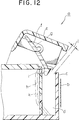
- the back lid f since the back lid f is moved in a limited space, it necessarily comes close to the tape b . Accordingly, if the back lid f is previously charged with static electricity, a part of the tape b can be lifted by the back lid f during its movement to its open position. As shown in Figure 12, there is defined a gap j between a lower end of the back lid f and an upper end of the tape slack preventing member c in the open position of the back lid f . As a result, there occurs a problem such that the part of the tape b lifted by the back lid f as mentioned above can move to the back side of the tape slack preventing member c through the gap j .
- a tape cassette having a housing of generally rectangular configuration containing reels on which a supply of tape is wound and having a top wall and a bottom wall and a peripheral wall extending between the top wall and the bottom wall along three sides of the housing so as to leave an opening along the fourth side of the housing, first and second cutouts communicating with the opening and extending along a portion of the fourth side of the housing, the tape being guided between the reels in a path having a run extending along the opening, a front lid mounted on the housing and being movable relative thereto between a closed position covering the opening and an open position exposing the opening, a back lid movable in conjunction with the movement of the front lid between the closed position where the back lid is positioned behind the front lid and the open position where the back lid is removed from behind the tape, a first rib formed on the bottom wall in a tape width direction behind said tape run, and a second rib formed on the edge of the back lid, the second rib facing the first rib so that the top edge of
- the second rib is formed on the back lid, and when the back lid is in the open position, the second rib is disposed in contact or proximity to the upper end of the first rib, thereby defining no gap between the first rib and the second rib. Accordingly, even when a part of the tape is lifted by the back lid in the lid opening operation, there is no possibility of the tape passing behind the first rib and tape jamming and damage to a tape player are prevented.
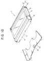
- a tape cassette 1 shown is for recording a signal of a high-definition (HD) system (which will be hereinafter referred to as an HD tape cassette).
- the HD tape cassette in this preferred embodiment has an external form like that of a so-called VHS tape cassette.
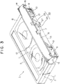
- the HD tape cassette 1 has the cassette case 2 constructed of an upper half 3 and a lower half 4 connected together to have a rectangular thin box-like configuration.
- the cassette case 2 includes a main portion 5 having almost the same external form, especially, dimensions (length, width and thickness) as that of the cassette case of the VHS tape cassette.
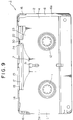
- An additional portion 6 projects from a right hand side of the main portion 5 (as viewed in Figure 10) and has a width in the front to rear direction equal to that of the main portion 5, a very small width in the right to left direction, e.g. about 3% of that of the main portion 5, and a thickness slightly smaller than that of the main portion 5, e.g. about 90% or less of that of the main portion 5.
- An upper surface of the additional portion 6 is flush with an upper surface of the main portion 5. Accordingly, a lower surface 6 a of the additional portion 6 is slightly higher than a lower surface 5 a of the main portion 5. That is, there is defined a shallow elongate recess extending between the front end and the rear at the right hand edge of the lower surface of the cassette case 2.
- An internal space of the main portion 5 is in full communication with that of the additional portion 6.
- the cassette case 2 is formed on its front surface with a tape drawing recess 7 which is elongate in the right to left direction. Upon loading the tape cassette 1 into a tape player, a member for drawing a magnetic tape 13 out of the cassette case 2 and a capstan are inserted into the tape drawing recess 7.
- a right hand portion of the tape drawing recess 7 (as viewed in Figure 2) is elongate somewhat more than a left portion thereof. This is due to the following reason. If the cassette case 2 of the HD tape cassette 1 and a cassette case of a VHS tape cassette are superimposed with each other with the left hand side surface of the cassette case 2 positioned flush with the left hand side surface of the cassette case of the VHS tape cassette, a plurality of independent recesses provided in the VHS tape cassette for inserting the tape drawing member and the capstan should be all included in the tape drawing recess 7 of the cassette case 2. This construction enables a tape player to be capable of employing either the VHS tape cassette or the HD tape cassette optionally.
- a portion of the right hand surface of the cassette case 2 on the right hand and left hand sides of the tape drawing recess 7 is open to form tape outlets 8 and 9.
- Two tape guides 10 are vertically formed in the tape outlets 8 and 9 at their inner ends on the sides of the tape drawing recess 7.
- a pair of tape reels 11 and 12 are rotatably accommodated in the cassette case 2, and opposite end portions of the magnetic tape 13 are wrapped around the tape reels 11 and 12.
- the magnetic tape 13 is partially led out of the cassette case 2 from the tape outlets 8 and 9.
- the lead-out portion of the magnetic tape 13 outside the cassette case 2 is guided at its opposite ends by the two tape guides 10 in a stretched condition in front of the tape drawing recess 7.
- a front lid 14 is provided for opening and closing the front surface of the cassette case 2 from which the magnetic tape 13 is drawn.
- the front lid 14 is integrally formed with a cover portion 15 having a substantially inverted L-shape in vertical cross section and with a pair of side portions 16 projecting rearwardly from the right and left sides of the cover portion 15.
- the side portions 16 of the front lid 14 are rotatably supported at two positions near the rear ends thereof to the right and left side surfaces of the cassette case 2 at two positions near the front ends thereof.
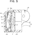
- the front lid 14 can be moved between a closed position shown in Figures 4 and 5 where a front surface of the magnetic tape 13 stretched along the front surface of the cassette case 2 is enclosed and an open position shown in Figures 6 and 7 where the cover position 15 is moved upwardly to open the front surface of the cassette case 2.
- a back lid 17 has a substantially thin plate-like shape and a length slightly smaller than the length of the tape drawing recess 7 of the cassette case 2.
- the back lid 17 is formed at its lower end with a projecting portion 18 projecting frontwardly and inclined downwardly.
- the back lid 17 is rotatably supported at opposite side positions near its upper ends to a pair of supporting portions 19 formed on the cover portion 15 of the front lid 14. Further, two pins 20 project sidewardly from the lower ends of the right and left sides of the back lid 17, and a pair of guide grooves 21 are formed on the right and left inner wall surfaces of the tape drawing recess 7 of the cassette case 2. The right and left pins 20 of the back lid 17 are slidably engaged with the right and left guide grooves 21 of the cassette case 2, respectively.
- the back lid 17 In the closed position of the front lid 14, the back lid 17 is in a closed position where a primary portion thereof covers a back surface of the magnetic tape 13 and a front end of the projecting portion 18 contacts a lower edge portion of a back surface of the cover portion 15 of the front lid 14 to enclose a lower side of the magnetic tape 13 as shown in Figures 4 and 5.
- the back lid 17 In the open position of the front lid 14, the back lid 17 is in an open position where it is located above the front end portion of the cassette case 2 as shown in Figures 6 and 7.
- the attitude of the back lid 17 is controlled by the position of the portion supported by the front lid 14 and the position of the pins 20 moving along the guide grooves 21.
- a tape slack preventing member 22 projects from the lower half 4 at an intermediate position between the middle and the right hand end of the tape drawing recess 7.
- the tape slack preventing member 22 comprises a base portion 24 integral with and projecting frontwardly from a bottom wall 23 of the lower half 4 and a first rib 25 projecting upwardly from a front end of the base portion 24.
- the first rib 25 In the closed position of the lids 14, 17 the first rib 25 is located, as shown in Figure 4, intermediate the front lid 14 and the back lid 17 and an upper end of the first rib 25 extends to a position substantially contacting an inner surface of an upper portion 15 a of the cover portion 15 of the front lid 14.
- An upper end surface of the first rib 25 is formed at its front end with an inclined surface 26 which is inclined downwardly.
- An opening 27 is formed through a connecting portion of the member 22 between the base portion 24 and the first rib 25 of the tape slack preventing member 22.
- a rear surface of the first rib 25 is formed with a slide groove 28 extending from the lower end to the upper end.
- the projecting portion 18 of the back lid 17 is formed with an escape cutout 29 so as to avoid interference between the projecting portion 18 and the first rib 25 during rotation of the back lid 17.
- a second rib 30 is located in the escape cutout 29 so as to project from the bottom of the cutout 29 substantially at the middle position thereof.
- the second rib 30 comprises a horizontal portion 30 a projecting frontwardly from the lower end of the primary portion of the back lid 17 and a vertical portion 30 b projecting downwardly from a front end of the horizontal portion 30 a .
- An outer surface of a connecting portion between the horizontal portion 30 a and the vertical portion 30 b is formed as an inclined surface 30 c inclined at an angle of about 45 degrees.
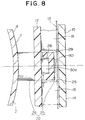
- the vertical portion 30 b of the second rib 30 In the closed position, the vertical portion 30 b of the second rib 30 is located in the opening 27 of the tape slack preventing member 22. During the rotation of the back lid 17 to the open position, the major part of the second rib 30 slides in the slide groove 28 of the first rib 25. When the open position is reached as shown in Figure 6, a front surface of the lower end portion of the vertical portion 30 b of the second rib 30 is pressed into contact with a back surface of the upper end portion of the first rib 25 and engaged in the slide groove 28.
- the upper end surface of the first rib 25 is formed at its front end with the inclined surface 26 which is inclined downwardly. Accordingly, even if a lower edge of the magnetic tape 13 lifted by the back lid 17 should ride up onto the upper end surface of the first rib 25, the lower edge of the magnetic tape 13 will slip down over the inclined surface 26 to be surely returned to the normal position.
- the inclined surface 30 c of the second rib 30 has the same function as that of the inclined surface 26 of the first rib 25.
- An erroneous insertion preventing groove 31 is formed at the middle of the front end portion of the bottom wall 23 of the cassette case 2 and extends in the front to rear direction into the tape drawing recess 7.
- the erroneous insertion preventing member 31 of the tape cassette 1 in this preferred embodiment is wider than that of the VHS tape cassette, and the projection 33 of the cassette holder 32 is accordingly wider than that of a cassette holder for the VHS tape cassette. Accordingly, in the event that an attempt is made to load a VHS tape cassette into a tape player dedicated for HD tape cassettes the projection 33 cannot be engaged in the erroneous insertion preventing groove of the VHS tape cassette and prevents such erroneous insertion.
Landscapes
- Packaging Of Annular Or Rod-Shaped Articles, Wearing Apparel, Cassettes, Or The Like (AREA)
- Impression-Transfer Materials And Handling Thereof (AREA)
Applications Claiming Priority (2)
| Application Number | Priority Date | Filing Date | Title |
|---|---|---|---|
| JP50222/91 | 1991-02-25 | ||
| JP3050222A JPH04271078A (ja) | 1991-02-25 | 1991-02-25 | テープカセット |
Publications (3)
| Publication Number | Publication Date |
|---|---|
| EP0501719A2 true EP0501719A2 (de) | 1992-09-02 |
| EP0501719A3 EP0501719A3 (en) | 1992-12-09 |
| EP0501719B1 EP0501719B1 (de) | 1996-04-17 |
Family
ID=12853023
Family Applications (1)
| Application Number | Title | Priority Date | Filing Date |
|---|---|---|---|
| EP92301520A Expired - Lifetime EP0501719B1 (de) | 1991-02-25 | 1992-02-24 | Bandkassette |
Country Status (7)
| Country | Link |
|---|---|
| US (1) | US5279476A (de) |
| EP (1) | EP0501719B1 (de) |
| JP (1) | JPH04271078A (de) |
| KR (1) | KR920017093A (de) |
| AU (1) | AU1120692A (de) |
| DE (1) | DE69209870T2 (de) |
| ES (1) | ES2086064T3 (de) |
Cited By (3)
| Publication number | Priority date | Publication date | Assignee | Title |
|---|---|---|---|---|
| EP0624874A3 (de) * | 1993-05-11 | 1995-02-01 | Victor Company Of Japan | Bandkassette. |
| EP0663663A1 (de) * | 1993-12-15 | 1995-07-19 | Sony Corporation | Bandkassette |
| US5543991A (en) * | 1992-11-24 | 1996-08-06 | Victor Company Of Japan, Ltd. | Tape cassette having a rear cover composed of two pieces of plates rotatably connected to each other |
Families Citing this family (4)
| Publication number | Priority date | Publication date | Assignee | Title |
|---|---|---|---|---|
| JP2778413B2 (ja) * | 1993-05-20 | 1998-07-23 | 日本ビクター株式会社 | テープカセット |
| MY111998A (en) * | 1994-02-03 | 2001-03-31 | Sony Corp | A tape cassette |
| US5675566A (en) * | 1994-10-31 | 1997-10-07 | Sony Corporation | Recording and/or reproducing apparatus and a cartridge for a recording medium |
| CN112336362B (zh) * | 2020-10-16 | 2023-03-31 | 东软医疗系统股份有限公司 | 安装机构、防护装置及医疗影像设备 |
Family Cites Families (7)
| Publication number | Priority date | Publication date | Assignee | Title |
|---|---|---|---|---|
| AU540710B2 (en) * | 1978-05-09 | 1984-11-29 | N.V. Philips Gloeilampenfabrieken | Magnetic tape cassette |
| JPS6128182U (ja) * | 1984-07-23 | 1986-02-20 | ソニー株式会社 | 磁気テ−プカセツト |
| JPH0454628Y2 (de) * | 1985-06-03 | 1992-12-22 | ||
| JPS63268177A (ja) * | 1987-04-24 | 1988-11-04 | Sony Corp | テ−プカセツト |
| JPH0525110Y2 (de) * | 1987-06-18 | 1993-06-24 | ||
| JP2725358B2 (ja) * | 1989-03-24 | 1998-03-11 | ソニー株式会社 | テープカセット |
| EP0400933B1 (de) * | 1989-05-29 | 1995-07-05 | Matsushita Electric Industrial Co., Ltd. | Bandkassette |
-
1991
- 1991-02-25 JP JP3050222A patent/JPH04271078A/ja active Pending
-
1992
- 1992-02-20 US US07/837,905 patent/US5279476A/en not_active Expired - Fee Related
- 1992-02-24 EP EP92301520A patent/EP0501719B1/de not_active Expired - Lifetime
- 1992-02-24 ES ES92301520T patent/ES2086064T3/es not_active Expired - Lifetime
- 1992-02-24 KR KR1019920002772A patent/KR920017093A/ko not_active Withdrawn
- 1992-02-24 DE DE69209870T patent/DE69209870T2/de not_active Expired - Fee Related
- 1992-02-24 AU AU11206/92A patent/AU1120692A/en not_active Abandoned
Cited By (5)
| Publication number | Priority date | Publication date | Assignee | Title |
|---|---|---|---|---|
| US5543991A (en) * | 1992-11-24 | 1996-08-06 | Victor Company Of Japan, Ltd. | Tape cassette having a rear cover composed of two pieces of plates rotatably connected to each other |
| EP0624874A3 (de) * | 1993-05-11 | 1995-02-01 | Victor Company Of Japan | Bandkassette. |
| EP0859363A1 (de) * | 1993-05-11 | 1998-08-19 | Victor Company Of Japan, Limited | Bandkassette |
| EP0663663A1 (de) * | 1993-12-15 | 1995-07-19 | Sony Corporation | Bandkassette |
| US5542621A (en) * | 1993-12-15 | 1996-08-06 | Sony Corporation | Tape cassette |
Also Published As
| Publication number | Publication date |
|---|---|
| US5279476A (en) | 1994-01-18 |
| ES2086064T3 (es) | 1996-06-16 |
| JPH04271078A (ja) | 1992-09-28 |
| EP0501719A3 (en) | 1992-12-09 |
| AU1120692A (en) | 1992-08-27 |
| DE69209870T2 (de) | 1996-09-05 |
| EP0501719B1 (de) | 1996-04-17 |
| DE69209870D1 (de) | 1996-05-23 |
| KR920017093A (ko) | 1992-09-26 |
Similar Documents
| Publication | Publication Date | Title |
|---|---|---|
| US4418373A (en) | Tape cassette | |
| US4214719A (en) | Tape cassette | |
| EP0406943B1 (de) | System zur Aufzeichnung/Wiedergabe von Signalen auf/vom Magnetband und Gerät und Kassette zur Verwendung in diesem System | |
| EP0438144B1 (de) | Bandkassette | |
| US5065955A (en) | Tape cassette having outer and inner lids locked by the inner lid | |
| US4898338A (en) | Magnetic tape cassette | |
| EP0501719B1 (de) | Bandkassette | |
| EP0473437B1 (de) | Bandkassette | |
| US5240200A (en) | Tape cassette | |
| US4809113A (en) | Tape cassette with improved cover structure | |
| US5198951A (en) | Tape cassette with magnetic tape outlets openable and closable by lids | |
| EP0452148B1 (de) | Bandkassette | |
| US5689393A (en) | Magnetic disk cartridge having an opening for a magnetic head on a side thereof | |
| US4311286A (en) | Fixed reel type endless tape cassette | |
| KR100274683B1 (ko) | 테이프 카세트 | |
| EP0400933A2 (de) | Bandkassette | |
| CA1323694C (en) | Cassette holding apparatus for a cassette tape player | |
| JPH06295556A (ja) | テープカセット | |
| KR100247960B1 (ko) | 테이프레코더 | |
| US5610778A (en) | Magnetic tape apparatus which senses and plays different types of cassette | |
| EP0920009B1 (de) | Magnetplattenkassette | |
| JP2629431B2 (ja) | テープカセット | |
| JPH0447818Y2 (de) | ||
| JPH05174538A (ja) | テープカセット | |
| JPS62202375A (ja) | テ−プカセツト |
Legal Events
| Date | Code | Title | Description |
|---|---|---|---|
| PUAI | Public reference made under article 153(3) epc to a published international application that has entered the european phase |
Free format text: ORIGINAL CODE: 0009012 |
|
| AK | Designated contracting states |
Kind code of ref document: A2 Designated state(s): DE ES FR GB |
|
| PUAL | Search report despatched |
Free format text: ORIGINAL CODE: 0009013 |
|
| AK | Designated contracting states |
Kind code of ref document: A3 Designated state(s): DE ES FR GB |
|
| 17P | Request for examination filed |
Effective date: 19930507 |
|
| 17Q | First examination report despatched |
Effective date: 19950511 |
|
| GRAA | (expected) grant |
Free format text: ORIGINAL CODE: 0009210 |
|
| AK | Designated contracting states |
Kind code of ref document: B1 Designated state(s): DE ES FR GB |
|
| REF | Corresponds to: |
Ref document number: 69209870 Country of ref document: DE Date of ref document: 19960523 |
|
| REG | Reference to a national code |
Ref country code: ES Ref legal event code: FG2A Ref document number: 2086064 Country of ref document: ES Kind code of ref document: T3 |
|
| ET | Fr: translation filed | ||
| PLBE | No opposition filed within time limit |
Free format text: ORIGINAL CODE: 0009261 |
|
| 26N | No opposition filed | ||
| PGFP | Annual fee paid to national office [announced via postgrant information from national office to epo] |
Ref country code: GB Payment date: 20010221 Year of fee payment: 10 Ref country code: DE Payment date: 20010221 Year of fee payment: 10 |
|
| REG | Reference to a national code |
Ref country code: GB Ref legal event code: IF02 |
|
| PGFP | Annual fee paid to national office [announced via postgrant information from national office to epo] |
Ref country code: FR Payment date: 20020212 Year of fee payment: 11 |
|
| PGFP | Annual fee paid to national office [announced via postgrant information from national office to epo] |
Ref country code: ES Payment date: 20020213 Year of fee payment: 11 |
|
| PG25 | Lapsed in a contracting state [announced via postgrant information from national office to epo] |
Ref country code: GB Free format text: LAPSE BECAUSE OF NON-PAYMENT OF DUE FEES Effective date: 20020224 |
|
| PG25 | Lapsed in a contracting state [announced via postgrant information from national office to epo] |
Ref country code: DE Free format text: LAPSE BECAUSE OF NON-PAYMENT OF DUE FEES Effective date: 20020903 |
|
| GBPC | Gb: european patent ceased through non-payment of renewal fee |
Effective date: 20020224 |
|
| PG25 | Lapsed in a contracting state [announced via postgrant information from national office to epo] |
Ref country code: ES Free format text: LAPSE BECAUSE OF NON-PAYMENT OF DUE FEES Effective date: 20030225 |
|
| PG25 | Lapsed in a contracting state [announced via postgrant information from national office to epo] |
Ref country code: FR Free format text: LAPSE BECAUSE OF NON-PAYMENT OF DUE FEES Effective date: 20031031 |
|
| REG | Reference to a national code |
Ref country code: FR Ref legal event code: ST |
|
| REG | Reference to a national code |
Ref country code: ES Ref legal event code: FD2A Effective date: 20030225 |