EP0501787A2 - Collecteur de courant glissant en céramique - Google Patents
Collecteur de courant glissant en céramique Download PDFInfo
- Publication number
- EP0501787A2 EP0501787A2 EP92301639A EP92301639A EP0501787A2 EP 0501787 A2 EP0501787 A2 EP 0501787A2 EP 92301639 A EP92301639 A EP 92301639A EP 92301639 A EP92301639 A EP 92301639A EP 0501787 A2 EP0501787 A2 EP 0501787A2
- Authority
- EP
- European Patent Office
- Prior art keywords
- ceramics
- peripheral surface
- current collector
- commutator
- rotary shaft
- Prior art date
- Legal status (The legal status is an assumption and is not a legal conclusion. Google has not performed a legal analysis and makes no representation as to the accuracy of the status listed.)
- Withdrawn
Links
Images


Classifications
-
- H—ELECTRICITY
- H01—ELECTRIC ELEMENTS
- H01R—ELECTRICALLY-CONDUCTIVE CONNECTIONS; STRUCTURAL ASSOCIATIONS OF A PLURALITY OF MUTUALLY-INSULATED ELECTRICAL CONNECTING ELEMENTS; COUPLING DEVICES; CURRENT COLLECTORS
- H01R39/00—Rotary current collectors, distributors or interrupters
- H01R39/02—Details for dynamo electric machines
- H01R39/022—Details for dynamo electric machines characterised by the materials used, e.g. ceramics
Definitions
- the present invention relates to a sliding current collector such as a slip ring, commutator or the like which is made of a composite ceramics material and which is used in electric rotary machines such as commutator-type motors and generators. More particularly, the present invention is concerned with a sliding current collector which is made of a composite ceramics material and which is suitable for use in comparatively small electric motors such as an automotive engine starter motor, a motor for use in a portable motor-driven tool, and so forth.
- Ceramics materials have been developed and used, including insulating ceramics which exhibit high insulation power well comparing with that of conventional insulators, as well as electrically conductive ceramics which exhibit electrical conductivity substantially the same as that of iron.
- Composite ceramics bodies also have been developed which are composed of highly insulating and highly conductive ceramics materials sintered into one body. Because of excellent mechanical strength and heat resistance, the composite ceramics bodies exhibit high resistances both to wear and sparking as compared with conventional materials such as carbon and copper and, hence, are expected to offer superior results when used as the material of a sliding current collector such as a slip ring or a commutator of an electric rotary machine.
- the ceramics materials generally exhibit only low levels of tensile strength, although the levels of compression strength are considerably high.
- the conventional methods (1) to (3) mentioned above, therefore, are not suitably used for ceramics current collectors because such collectors are easily broken due to cracking caused by tensile stress generated in the ring-shaped sliding current collector.
- the known method (4) mentioned above also is inadequate in that the sliding current collector cannot be precisely located and centered because it is fixed by means of the resin which is deposited to and around the ends of the current collector.
- an object of the present invention is to provide a sliding current collector made of a ceramics material which can be mounted on and fixed to a rotary shaft without any angular and axial positional slippage and without suffering from cracking and other damages.
- a sliding current collector which is fixed to a rotary shaft through, at least, a resin layer.
- a predetermined annular gap is preserved between the inner peripheral surface of the ceramics sliding current collector and the outer peripheral surface of the rotary shaft and the gap is filled with a resin followed by setting or curing of the resin, whereby the above-mentioned resin layer is formed so as to fix the ceramics sliding current collector to the rotary shaft.
- This resin layer also is effective in absorbing any stress which may otherwise be transmitted from the rotary shaft to the ceramics sliding current collector.
- Axial positioning and centering of the ceramics sliding current collector with respect to the rotary shaft can be performed accurately by the use of a resin casting mold which is prepared beforehand or the use of suitable locating members placed in the above-mentioned annular gap, thus ensuring a high dimensional precision.
- Fig. 2 shows a D.C. motor used as a starter motor, as an example of the electric rotary machine which incorporates an embodiment of the ceramics sliding current collector in accordance with the present invention.
- the motor generally denoted by 1 has a stator 2 serving as a field generator, a rotor 3, a commutator 4, a brush holder 5, brushes 6, bearings 7, a shaft 8, rotor coils 9, and so forth, as known per se.
- the commutator 4 is a ceramics commutator as an embodiment of the ceramics sliding current collector of the present invention.
- the ceramics commutator 4 is a ceramics composite body composed of a conductive portion 4a made of a conductive ceramics material, an insulating portion 4b made of an insulating material, and an extension 4c of the conductive portion 4a. Armature coils 9 are connected to the extension 4c of the conductive portion 4a.
- Numeral 4d denotes a resin layer.
- the ceramics commutator 4 has a substantially cylindrical bore which receives a shaft 8.
- the diameter of the cylindrical bore in the ceramics commutator 4 has a diameter which is greater by a predetermined amount than the outside diameter of the shaft 8 so that a predetermined annular gap is formed between the inner peripheral surface of the ceramics commutator 4 and the outer peripheral surface of the shaft 8.
- a resin is charged in this gap and then set or cured to form the above-mentioned resin layer 4d.
- thermosetting resin ordinarily used in rotary electric machines, such as a phenol resin or an epoxy resin, can be used as the material of the resin layer 4d.
- thermosetting resins which are used nowadays specifically for commutators can be used most suitably.
- the size of the annular gap between the ceramics commutator 4 and the shaft 8 can be set to any desired value provided that the gap is large enough to be filled with the resin. More specifically, the size of the gap is determined in consideration of various factors such as the fluidity of the resin at the time of filling and filling method such as vacuum filling or other method. Practically, however, the size ranges from 0.05 to 1.0 mm.
- the ceramics commutator 4 is fixed to the shaft 8 through the intermediary of the resin layer 4d, i.e., through the bonding force given by the resin layer 4d. Any stress which is generated, for example, by thermal expansion of the shaft 8 can be well absorbed by deformation of the resin layer 4d. Consequently, generation of tensile stress which hitherto has been inevitable in conventional commutator can be avoided, whereby cracking and other damaging of the ceramics commutator 4 are avoided, thus ensuring sufficient reliability of the ceramics commutator.
- the ceramics commutator 4 can be fixed to the shaft 8 simply by the provision of the resin layer 4d.
- This work is very easy to conduct and required strength can easily be developed thanks to the use of a thermosetting resin such as a phenol resin or an epoxy resin.
- cost of production can be reduced appreciably.
- the object of the invention can be well achieved merely by filing the annular gap with the resin and setting the resin into the resin layer 4d. In some cases, however, a specifically large bonding strength may be required.
- the arrangement may be such that both the inner peripheral surface of the ceramics commutator 4 and the outer peripheral surface of the shaft 8 are provided with grooves so that protrusions 4e may be formed on the resin layer 4d so as to bite in the grooves. According to this arrangement, the area of bonding between the resin layer 4d and the surfaces of the ceramics commutator 4 and the shaft 8 is increased so as to enhance the bonding strength.
- the protrusions 4e may have a rectangular form as illustrated or may be round or spiral. Any suitable configuration can be adopted provided that it facilitates the work and increases the area of bonding.
- the embodiment employing the protrusions 4e offers an additional advantage in that it facilitates positioning of the ceramics commutator 4 with respect to the shaft 8 in the rotational direction and enhances the precision of such positioning, when forming the resin layer 4d after insertion of the shaft 8 into the ceramics commutator 4, by virtue of the grooves which are formed in both members and which serve as indexing means.
- both the inner peripheral surface of the ceramics commutator 4 and the outer peripheral surface of the shaft 8 are provided with grooves and the grooves in both members are aligned in angular direction.
- the grooves may be formed only in one of the inner peripheral surface of the ceramics commutator 4 and the outer peripheral surface of the shaft 8 while the other surface is smooth. It is also possible to arrange such that the grooves formed in the inner peripheral surface of the ceramics commutator 4 and the grooves formed in the outer peripheral surface of the shaft 8 are staggered in the rotational direction. The arrangement also may be such that the grooves formed in the inner peripheral surface of the ceramics commutator 4 and the grooves formed in the outer peripheral surface of the shaft 8 have different configurations.
- charging of the resin of a high viscosity into the gap between the ceramics commutator 4 and the shaft 8 is conducted by charging the resin into the portions of the gap having greater cross-sectional area so that the resin can smoothly move into and fill the narrow portions of the gap.
- a ceramics commutator 4 in contrast to the embodiment shown in Figs. 1A and 1B in which the ceramics commutator 4 is fixed to the shaft 8 only through the intermediary of the resin layer 4d, a ceramics commutator 4; as the second embodiment employs a metallic cylindrical member 10 which is disposed inside thereof so that an annular gap is formed between the outer peripheral surface of the metallic cylindrical member 10 and the inner peripheral surface of the ceramics commutator 4′.
- a resin layer 4d is formed in this annular gap. This resin layer 4d is formed in the same method as that described before in connection with the first embodiment.
- a subassembly composed of the ceramics commutator 4′, resin layer 4d and the cylindrical metallic member 10 is formed as an integral member which is separate from the shaft 8 of the motor (see Fig. 2) and this integral member is mounted on the shaft 8 as illustrated in Fig. 2.
- the first embodiment shown in Figs. 1A and 1B essentially requires that the ceramics commutator 4 is correctly positioned and held with respect to the shaft 8 concentrically therewith during the period of charging of the thermoplastic resin for fixing the commutator 4; to the shaft 8.
- the ceramics commutator 4′ is first fixed to the metallic cylindrical member 10 by means of the resin to form a sub-assembly and this sub-assembly is fixed to the shaft by a conventional method such as press-fitting with the aid of a key which engages with keyways formed both in the metallic cylindrical member 10 and the shaft 8.
- a conventional method such as press-fitting with the aid of a key which engages with keyways formed both in the metallic cylindrical member 10 and the shaft 8.
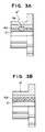
- Fig. 3B shows a modification which employs a different configuration of the protrusions 4e from that of the embodiment shown in Fig. 3A.
- Other portions are materially the same as those of the embodiment of Fig. 3A.
- the metallic cylindrical member 10 is fixed to the ceramics commutator 4′ through the resin layer 4d, i.e., by the bonding force developed by the resin layer 4d.
- any stress generated, for example, by a thermal expansion of the shaft 8 is absorbed by a deformation of the resin layer 4d, so that generation of tensile stress in the ceramics commutator 4; is avoided to prevent damaging of the commutator 4′, thus improving the reliability of the same.
- the embodiment and the modification shown in figs. 3A and 3B may be provided with axial grooves formed in the ceramics commutator 4′ and/or the shaft 8 as in the case of the embodiment shown in figs. 1A and 1B, in order to facilitate the injection of the resin.
- only one such axial groove is sufficient, because the indexing of the commutator with respect to the shaft is unnecessary in these cases.
- the present invention offers the following advantages by virtue of the structural features described hereinbefore.
- the present invention makes it possible to form an integral assembly including the shaft, ceramics commutator, coil and the core by means of a resin. This appreciably shorten the time required for the production of the electric rotary machine and to prevent any slippage of the ceramics commutator from the center of the shaft.
Landscapes
- Chemical & Material Sciences (AREA)
- Engineering & Computer Science (AREA)
- Ceramic Engineering (AREA)
- Motor Or Generator Current Collectors (AREA)
Applications Claiming Priority (2)
| Application Number | Priority Date | Filing Date | Title |
|---|---|---|---|
| JP55685/91 | 1991-02-28 | ||
| JP3055685A JPH05219690A (ja) | 1991-02-28 | 1991-02-28 | セラミックス摺動集電体 |
Publications (2)
| Publication Number | Publication Date |
|---|---|
| EP0501787A2 true EP0501787A2 (fr) | 1992-09-02 |
| EP0501787A3 EP0501787A3 (fr) | 1992-12-30 |
Family
ID=13005758
Family Applications (1)
| Application Number | Title | Priority Date | Filing Date |
|---|---|---|---|
| EP19920301639 Withdrawn EP0501787A3 (fr) | 1991-02-28 | 1992-02-26 | Collecteur de courant glissant en céramique |
Country Status (3)
| Country | Link |
|---|---|
| US (1) | US5208502A (fr) |
| EP (1) | EP0501787A3 (fr) |
| JP (1) | JPH05219690A (fr) |
Cited By (5)
| Publication number | Priority date | Publication date | Assignee | Title |
|---|---|---|---|---|
| WO2004038905A3 (fr) * | 2002-10-28 | 2004-09-23 | Kolektor D O O | Commutateur pour machine electrique et procede pour le realiser |
| US6894419B2 (en) * | 2001-02-28 | 2005-05-17 | Mitsubishi Denki Kabushiki Kaisha | Current passing circuit board for rotary electric machine inserted in molded resin |
| WO2011036132A1 (fr) * | 2009-09-23 | 2011-03-31 | Robert Bosch Gmbh | Collecteur commutateur pour la transmission d'énergie dans une machine électrique |
| WO2012041922A1 (fr) * | 2010-10-01 | 2012-04-05 | Hoffmann & Co., Elektrokohle Ag | Système de transfert de courant pour machines et installations électromécaniques |
| US9819248B2 (en) | 2012-12-31 | 2017-11-14 | Teco-Westinghouse Motor Company | Assemblies and methods for cooling electric machines |
Families Citing this family (38)
| Publication number | Priority date | Publication date | Assignee | Title |
|---|---|---|---|---|
| JPH07312851A (ja) * | 1994-03-23 | 1995-11-28 | Mitsubishi Electric Home Appliance Co Ltd | セラミックス摺動集電体 |
| US7274549B2 (en) * | 2000-12-15 | 2007-09-25 | X2Y Attenuators, Llc | Energy pathway arrangements for energy conditioning |
| US6894884B2 (en) * | 1997-04-08 | 2005-05-17 | Xzy Attenuators, Llc | Offset pathway arrangements for energy conditioning |
| US7321485B2 (en) | 1997-04-08 | 2008-01-22 | X2Y Attenuators, Llc | Arrangement for energy conditioning |
| US6606011B2 (en) * | 1998-04-07 | 2003-08-12 | X2Y Attenuators, Llc | Energy conditioning circuit assembly |
| US7336468B2 (en) | 1997-04-08 | 2008-02-26 | X2Y Attenuators, Llc | Arrangement for energy conditioning |
| US7110227B2 (en) * | 1997-04-08 | 2006-09-19 | X2Y Attenuators, Llc | Universial energy conditioning interposer with circuit architecture |
| US6603646B2 (en) | 1997-04-08 | 2003-08-05 | X2Y Attenuators, Llc | Multi-functional energy conditioner |
| US6018448A (en) | 1997-04-08 | 2000-01-25 | X2Y Attenuators, L.L.C. | Paired multi-layered dielectric independent passive component architecture resulting in differential and common mode filtering with surge protection in one integrated package |
| US7301748B2 (en) | 1997-04-08 | 2007-11-27 | Anthony Anthony A | Universal energy conditioning interposer with circuit architecture |
| US7110235B2 (en) | 1997-04-08 | 2006-09-19 | Xzy Altenuators, Llc | Arrangement for energy conditioning |
| US9054094B2 (en) | 1997-04-08 | 2015-06-09 | X2Y Attenuators, Llc | Energy conditioning circuit arrangement for integrated circuit |
| US7042703B2 (en) | 2000-03-22 | 2006-05-09 | X2Y Attenuators, Llc | Energy conditioning structure |
| US7106570B2 (en) * | 1997-04-08 | 2006-09-12 | Xzy Altenuators, Llc | Pathway arrangement |
| US6650525B2 (en) | 1997-04-08 | 2003-11-18 | X2Y Attenuators, Llc | Component carrier |
| US20020079116A1 (en) | 2000-10-17 | 2002-06-27 | X2Y Attenuators, Llc | Amalgam of shielding and shielded energy pathways and other elements for single or multiple circuitries with common reference node |
| US20030161086A1 (en) | 2000-07-18 | 2003-08-28 | X2Y Attenuators, Llc | Paired multi-layered dielectric independent passive component architecture resulting in differential and common mode filtering with surge protection in one integrated package |
| US7336467B2 (en) * | 2000-10-17 | 2008-02-26 | X2Y Attenuators, Llc | Energy pathway arrangement |
| US7427816B2 (en) | 1998-04-07 | 2008-09-23 | X2Y Attenuators, Llc | Component carrier |
| JP2003526195A (ja) * | 1998-04-07 | 2003-09-02 | エクストゥーワイ、アテニュエイタズ、エル、エル、シー | 部品キャリア |
| US7113383B2 (en) * | 2000-04-28 | 2006-09-26 | X2Y Attenuators, Llc | Predetermined symmetrically balanced amalgam with complementary paired portions comprising shielding electrodes and shielded electrodes and other predetermined element portions for symmetrically balanced and complementary energy portion conditioning |
| EP1312148A4 (fr) | 2000-08-15 | 2009-06-03 | X2Y Attenuators Llc | Systeme d'electrodes pour conditionnement d'energie en circuit |
| US7193831B2 (en) | 2000-10-17 | 2007-03-20 | X2Y Attenuators, Llc | Energy pathway arrangement |
| FR2830245B1 (fr) * | 2001-09-28 | 2004-01-02 | Otis Elevator Co | Dispositif d'entrainement compact notamment pour la translation des portes de cabine d'ascenseur,ensemble moteur et reducteur de vitesse utilise et linteau support |
| US20030129855A1 (en) * | 2001-12-21 | 2003-07-10 | Douglas Richard E. | Current collector assembly and method |
| DE10223361C1 (de) * | 2002-05-25 | 2003-12-24 | Bosch Gmbh Robert | Kommutator für Elektromotoren |
| US7180718B2 (en) | 2003-01-31 | 2007-02-20 | X2Y Attenuators, Llc | Shielded energy conditioner |
| US7440252B2 (en) | 2003-05-29 | 2008-10-21 | X2Y Attenuators, Llc | Connector related structures including an energy conditioner |
| JP2006528868A (ja) | 2003-07-21 | 2006-12-21 | エックストゥーワイ アテニュエイターズ,エルエルシー | フィルタ組立体 |
| EP1698033A4 (fr) | 2003-12-22 | 2010-07-21 | X2Y Attenuators Llc | Conditionneur d'energie a blindage interne |
| US7817397B2 (en) | 2005-03-01 | 2010-10-19 | X2Y Attenuators, Llc | Energy conditioner with tied through electrodes |
| WO2006104613A2 (fr) | 2005-03-01 | 2006-10-05 | X2Y Attenuators, Llc | Conditionneur a conducteurs coplanaires |
| WO2006099297A2 (fr) | 2005-03-14 | 2006-09-21 | X2Y Attenuators, Llc | Conditionneur a conducteurs coplanaires |
| KR101390426B1 (ko) | 2006-03-07 | 2014-04-30 | 엑스2와이 어테뉴에이터스, 엘.엘.씨 | 에너지 컨디셔너 구조물들 |
| GB0800464D0 (en) * | 2008-01-11 | 2008-02-20 | Johnson Electric Sa | Improvement in or relating to a commutator |
| DE102013005627A1 (de) * | 2013-04-04 | 2014-10-09 | SIEVA d.o.o. - poslovna enota Idrija | Rotor einer dynamoelektrischen Maschine |
| WO2016129239A1 (fr) * | 2015-02-12 | 2016-08-18 | パナソニックIpマネジメント株式会社 | Commutateur, moteur électrique et procédé de production du commutateur |
| CN111009791B (zh) * | 2019-12-26 | 2024-11-22 | 河南和实科技有限公司 | 一种接地装置复合金属摩擦盘及其生产工艺 |
Family Cites Families (11)
| Publication number | Priority date | Publication date | Assignee | Title |
|---|---|---|---|---|
| US3777367A (en) * | 1971-12-02 | 1973-12-11 | Ametek Inc | Method of fabricating a commutator |
| US3766634A (en) * | 1972-04-20 | 1973-10-23 | Gen Electric | Method of direct bonding metals to non-metallic substrates |
| US3911553A (en) * | 1974-03-04 | 1975-10-14 | Gen Electric | Method for bonding metal to ceramic |
| JPS5254102A (en) * | 1975-10-29 | 1977-05-02 | Sony Corp | Method of manufacturing commutator |
| DE3242703A1 (de) * | 1982-11-19 | 1984-05-24 | Robert Bosch Gmbh, 7000 Stuttgart | Verfahren zum herstellen eines kommutatorsegmentringes |
| EP0127801B1 (fr) * | 1983-06-03 | 1986-10-22 | Asea Brown Boveri Ag | Commutateur pour une machine électrique et procédé pour le fabriquer |
| JPH063982B2 (ja) * | 1983-08-12 | 1994-01-12 | 株式会社日立製作所 | 摺動集電体の製造方法 |
| JPS60200745A (ja) * | 1984-03-23 | 1985-10-11 | Hitachi Ltd | 交流発電機用回転子 |
| JPS63137547U (fr) * | 1987-02-23 | 1988-09-09 | ||
| JPS63265550A (ja) * | 1987-04-20 | 1988-11-02 | Hitachi Ltd | 回転電機の電機子製造法 |
| FR2615049B1 (fr) * | 1987-05-04 | 1989-06-16 | Alsthom | Collecteur pour machine electrique tournante et procede de fabrication de ce collecteur |
-
1991
- 1991-02-28 JP JP3055685A patent/JPH05219690A/ja not_active Withdrawn
-
1992
- 1992-02-26 EP EP19920301639 patent/EP0501787A3/fr not_active Withdrawn
- 1992-02-27 US US07/842,484 patent/US5208502A/en not_active Expired - Fee Related
Cited By (5)
| Publication number | Priority date | Publication date | Assignee | Title |
|---|---|---|---|---|
| US6894419B2 (en) * | 2001-02-28 | 2005-05-17 | Mitsubishi Denki Kabushiki Kaisha | Current passing circuit board for rotary electric machine inserted in molded resin |
| WO2004038905A3 (fr) * | 2002-10-28 | 2004-09-23 | Kolektor D O O | Commutateur pour machine electrique et procede pour le realiser |
| WO2011036132A1 (fr) * | 2009-09-23 | 2011-03-31 | Robert Bosch Gmbh | Collecteur commutateur pour la transmission d'énergie dans une machine électrique |
| WO2012041922A1 (fr) * | 2010-10-01 | 2012-04-05 | Hoffmann & Co., Elektrokohle Ag | Système de transfert de courant pour machines et installations électromécaniques |
| US9819248B2 (en) | 2012-12-31 | 2017-11-14 | Teco-Westinghouse Motor Company | Assemblies and methods for cooling electric machines |
Also Published As
| Publication number | Publication date |
|---|---|
| US5208502A (en) | 1993-05-04 |
| EP0501787A3 (fr) | 1992-12-30 |
| JPH05219690A (ja) | 1993-08-27 |
Similar Documents
| Publication | Publication Date | Title |
|---|---|---|
| US5208502A (en) | Sliding current collector made of ceramics | |
| KR100893446B1 (ko) | 교류 발전기 | |
| US6002194A (en) | Rotor for a dynamo-electric machine | |
| AU674784B2 (en) | Electric rotating machine | |
| US7685697B2 (en) | Method of manufacturing an electric motor of a power tool and of manufacturing the power tool | |
| US6946758B2 (en) | Dynamoelectric machine having encapsulated coil structure with one or more of phase change additives, insert molded features and insulated pinion | |
| US8203239B2 (en) | Method of forming a power tool | |
| US8171616B2 (en) | Method of making an armature | |
| CN110474491B (zh) | 旋转电机的转子及旋转电机 | |
| CN1180456A (zh) | 注射成型的电动机组件及其制造方法 | |
| EP1522134A2 (fr) | Machine electrodynamique a enroulements enrobes | |
| US20040155550A1 (en) | Armature having teeth | |
| GB2059177A (en) | Electrical machine | |
| JP2002064951A (ja) | 永久磁石埋め込み型ロータ | |
| US5804905A (en) | Electric disk armature machine | |
| US6566780B2 (en) | Rotary electric machine having reinforcing ring on armature | |
| KR100225817B1 (ko) | 세라믹스 슬라이드집전체 및 그 제조방법 | |
| JP3508322B2 (ja) | 回転電機 | |
| JPH11150929A (ja) | 回転電機の電機子及びその製造方法 | |
| SU1472979A1 (ru) | Автомобильный генератор | |
| JPS63249446A (ja) | 回転電機用整流子の製造法 | |
| JP2580093B2 (ja) | 組立式整流子を備えた小型モータ | |
| JPH04275048A (ja) | 組立式整流子を備えた小型モータ | |
| HUP0105241A2 (hu) | Villamos gépek, különösen jármű-indítómotorok, kommutátora és eljárás ennek előállítására | |
| JPH04355649A (ja) | 組立式整流子を備えた小型モータ |
Legal Events
| Date | Code | Title | Description |
|---|---|---|---|
| PUAI | Public reference made under article 153(3) epc to a published international application that has entered the european phase |
Free format text: ORIGINAL CODE: 0009012 |
|
| AK | Designated contracting states |
Kind code of ref document: A2 Designated state(s): DE FR GB SE |
|
| PUAL | Search report despatched |
Free format text: ORIGINAL CODE: 0009013 |
|
| AK | Designated contracting states |
Kind code of ref document: A3 Designated state(s): DE FR GB SE |
|
| 17P | Request for examination filed |
Effective date: 19930621 |
|
| 17Q | First examination report despatched |
Effective date: 19940923 |
|
| 18W | Application withdrawn |
Withdrawal date: 19941220 |