EP0501820B1 - Carter de téléphone extensible - Google Patents
Carter de téléphone extensible Download PDFInfo
- Publication number
- EP0501820B1 EP0501820B1 EP92301719A EP92301719A EP0501820B1 EP 0501820 B1 EP0501820 B1 EP 0501820B1 EP 92301719 A EP92301719 A EP 92301719A EP 92301719 A EP92301719 A EP 92301719A EP 0501820 B1 EP0501820 B1 EP 0501820B1
- Authority
- EP
- European Patent Office
- Prior art keywords
- casing
- main casing
- telephone
- pair
- auxiliary
- Prior art date
- Legal status (The legal status is an assumption and is not a legal conclusion. Google has not performed a legal analysis and makes no representation as to the accuracy of the status listed.)
- Expired - Lifetime
Links
Images






Classifications
-
- H—ELECTRICITY
- H04—ELECTRIC COMMUNICATION TECHNIQUE
- H04M—TELEPHONIC COMMUNICATION
- H04M1/00—Substation equipment, e.g. for use by subscribers
-
- H—ELECTRICITY
- H04—ELECTRIC COMMUNICATION TECHNIQUE
- H04M—TELEPHONIC COMMUNICATION
- H04M1/00—Substation equipment, e.g. for use by subscribers
- H04M1/02—Constructional features of telephone sets
- H04M1/0202—Portable telephone sets, e.g. cordless phones, mobile phones or bar type handsets
- H04M1/0206—Portable telephones comprising a plurality of mechanically joined movable body parts, e.g. hinged housings
- H04M1/0208—Portable telephones comprising a plurality of mechanically joined movable body parts, e.g. hinged housings characterized by the relative motions of the body parts
- H04M1/0235—Slidable or telescopic telephones, i.e. with a relative translation movement of the body parts; Telephones using a combination of translation and other relative motions of the body parts
- H04M1/0237—Sliding mechanism with one degree of freedom
-
- H—ELECTRICITY
- H04—ELECTRIC COMMUNICATION TECHNIQUE
- H04M—TELEPHONIC COMMUNICATION
- H04M1/00—Substation equipment, e.g. for use by subscribers
- H04M1/02—Constructional features of telephone sets
- H04M1/0202—Portable telephone sets, e.g. cordless phones, mobile phones or bar type handsets
-
- H—ELECTRICITY
- H04—ELECTRIC COMMUNICATION TECHNIQUE
- H04M—TELEPHONIC COMMUNICATION
- H04M1/00—Substation equipment, e.g. for use by subscribers
- H04M1/02—Constructional features of telephone sets
- H04M1/03—Constructional features of telephone transmitters or receivers, e.g. telephone hand-sets
Definitions
- the present invention relates to an improved extendible telephone having a body casing or main casing incorporating a receiver and an operation casing or auxiliary casing incorporating a transmitter and dial keys.
- a portable radio telephone for example, should preferably be small size and light weight since it is carried by the user. It is a common practice with this kind of telephone to connect an auxiliary casing having a transmitter foldably or openably to a main casing having a receiver and dial keys by a hinge mechanism. To use the telephone, the user unfolds or opens the auxiliary casing away from the main casing to a position where a desired angle for conversation is set up and the receiver and transmitter are spaced apart by a desired distance.
- the hinge mechanism is relatively bulky since it has to have a sufficient mechanical strength, obstructing the decrease in the size and weight of the telephone while degrading portability.
- wirings between the main and auxiliary casings should be set up by way of the hinge mechanism and are, therefore, troublesome to in turn complicate the assembly of the telephone.
- An extendible telephone as distinguished from a foldable telephone, is also conventional.
- an auxiliary casing having a transmitter and dial keys is slidably mounted on a main casing having a receiver by a guide mechanism.
- the auxiliary casing is slid via the guide mechanism to an extended position where the receiver and the transmitter are spaced apart by a desired Distance.
- the auxiliary casing is contracted to a position suitable for the telephone to be put in, for example, the user's pocket.
- the extendible telephone has the guide mechanism having guides and guide channels thereof exposed to the outside of the main and auxiliary casing, not only the appearance is degraded, but also the design freedom is limited.
- the guide mechanism causes the guides and guide channels to slide on each other during extension and contraction, causing the main and auxiliary casings to wear. It follows that at least the contacting portions of the telephone, i. e. , the main and auxiliary casings have to be made of a material which are high slidable and resistive to wear, increasing the cost of the telephone. Furthermore, replacing the main and auxiliary casings and due to wear is troublesome and further increases the cost of the the telephone.
- an object of the present invention to provide an extendible telephone which is small size, light weight and highly portable.
- an extendible telephone having a main casing provided at least with a receiver and a slide surface, and an auxiliary casing provided at least with a transmitter and mounted on the main casing to be extendible from the main casing in a sliding motion
- a back plate member fastened to the back of the auxiliary casing which faces the slide surface of the main casing, slide members intervening between the slide surface of the main casing and the back plate member for allowing the auxiliary casing to slide relative to the main casing to either of an extended position and a contracted position, and a support member for connecting the back plate member slidably to the slide surface of the main casing via the slide members.
- the foldable telephone generally 10
- the foldable telephone has a main casing 12, an auxiliary casing 18, and a hinge mechanism 22 including a shaft 22a on which the auxiliary casing 18 is mounted to be rotatable toward and away from the main casing 12.
- the main casing 12 is provided with a receiver 14 and dial keys 16 while the auxiliary casing 18 is provided with a transmitter 20.
- the user rotates or unfolds the auxiliary casing 18 about the shaft 22a in a direction indicated by an arrow A in FIG. 1B.
- the auxiliary casing 18 is locked on reaching a position indicated by a phantom line in FIGS.
- a position there a desired angle for conversation is provided between the main and auxiliary casings 12 and 18 and a desired distance is provided between the receiver 14 and the transmitter 20.
- the user folds the auxiliary casing 18 in a direction B to a position indicated by a solid line in the figures and may put the telephone 10 in, for example, a pocket.
- the problem with the foldable telephone 10 is that the hinge mechanism 22 is exposed to the outside of the main and auxiliary casings 12 and 18 for structural reasons, limiting the design freedom, as discussed earlier.
- the hinge mechanism 22 is bulky since it has to have a mechanical strength great enough to withstand the opening and closing motion of the auxiliary casing 18, obstructing the decrease in the size and weight of the telephone 10 while degrading portability.
- wirings between the main and auxiliary casings 18 should be set up by way of the hinge mechanism 22 and are, therefore, troublesome to in turn complicate the assembly of the telephone 10.
- FIGS. 2A and 2B show a conventional extendible telephone, generally 24.
- the extendible telephone 24 has a main casing 26 including a receiver 28.
- An auxiliary casing 30 is slidably mounted on the main casing 26, i. e., extendible from the main casing 26 and includes a transmitter 32 and dial keys 34.
- a rectangular hole 26b is formed through the main casing 26.
- a stop 36 is formed by bending a leaf spring and received in the hole 26b while partly protruding from the surface 26a of the main casing 26 on which the auxiliary casing 30 is slidable.
- Guide channels 38 are formed on laterally opposite ends of the main casing 26.
- a back plate 40 is affixed to the back of the auxiliary casing 30 and formed with two positioning holes 40a and 40b which are spaced apart by a predetermined distance in the longitudinal direction of the plate 40.
- Guides 42 are formed on the inner periphery of opposite side walls of the auxiliary casing 30, and each has a generally L-shaped cross-section. The guides 42 of the auxiliary casing 30 mate with the guide channels 38 of the main casing 26.
- the auxiliary casing 30 is mounted on the main casing 26 by having the guides 42 thereof mated with the guide channels 38 and then being slid in a direction C until the postioning hole 40b mates with the stop 36.
- the auxiliary casing 30 with the back plate 40 is extended from the main casing 26, so that the telephone 24 may be used.
- FIG. 2C when the auxiliary casing 30 is further slid in the direction C on the main casing 26 until the other positioning hole 40a mates with the stop 36, the casing 30 fulls lies on the sliding surface 26a of the casing 26. In such a contracted position, the telephone 24 may be put in, for example, the user's pocket.
- the edge of the positioning hole 40a abutting against the stop 36 is arcuate.
- the casing 30 moves in the direction D while pressing the stop 36 downward along the arcuate edge 44 thereof.
- the auxiliary casing 30 is movable in the direction D to the previously stated position of FIG. 2B.
- the guide channels 38 and guides 42 of the telephone 24 are exposed to the outside, they not only degrade the appearance of the telephone 24 but also limit the design freedom.
- the guide channels 38 and guides 42 slide on each other during extension and contraction, causing the main and auxiliary casings 26 and 30 to wear.
- the casings 26 and 30 have to be made of a material which is highly slidable and resistive to wear, increasing the cost of the telephone 24.
- replacing the main and auxiliary casings 26 and 30 due to wear is troublesome and further increases the cost.
- an extendible telephone embodying the present invention is shown and generally designated by the reference numeral 50.
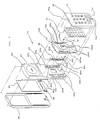
- the telephone 50 includes a main casing 60 having a receiver 62 and a slide surface 64.
- An auxiliary casing 70 has a transmitter 72 and dial keys 74.
- a pair of rail members 80 are affixed to the slide surface 64 of the main casing 60.
- a hook member 90 is affixed to the back of the main casing 60 while a back plate 100 is affixed to the back of the auxiliary casing 70.
- a printed circuit board 66 and a rear cover 68 are also affixed to the back of the main casing 60, and another printed circuit board 76 is affixed to the back of the auxiliary casing 70.
- a pair of grooves 60a are formed in the slide surface 64 of the main casing 60 in close proximity to opposite edges of the casing 60 and in symmetrical positions in the lateral direction.
- the grooves 60a have such a length that they will not be exposed to the outside when the auxiliary casing 70 is extended from the main casing 60 to a position where the telephone 50 is usable.
- Each groove 60a is deeper at an intermediate portion than at opposite end portions with respect to the longitudinal direction, i. e., in the extendible direction of the telephone 50.
- a pair of guide slots 60b extend in parallel to the grooves 60a and are located closer to opposite edges of the slide surface 64 than the grooves 60a.
- the guide slots 60b have a length corresponding to a distance over which the auxiliary casing 70 is movable relative to the main casing 60.
- a pair of rectangular holes 60c are each positioned above and in alignment with respective one of the guide slots 60b.
- the main casing 60 is provided with a hole 60d and a pawl 60e at, respectively, the upper edge and the lower edge of the slide surface 64.
- the auxiliary casing 60 has a lug 70a at the upper edge thereof which mates with the hole 60d and a hole 70b at the lower edge which mates with the pawl 60e.
- the rail members 80 have a configuration complementary to the configuration of the grooves 60a of the main casing 60, and each is made up of a flat portion 80a and a bulged portion 80b extending in the longitudinal direction of the flat portion 80a. Further, each rail member 80 has pawls 80c and 80d at opposite ends thereof, and an angled lug 80e located substantially at the center of the bulged portion 80b. A pair of pawls 90a extend from opposite ends of the hook member 90 and extend throughout the pair of rectangular holes 60c of the main casing 60.
- the back plate 100 On the surface facing the slide surface 64 of the main casing 60, the back plate 100 has a pair of pawls 100a to be slidably received in the guide slots 60b of the main casing 60, two spaced pairs of angled recesses 100b and 100c selectively engageable wth the angled lugs 80e of the rail members 80, and an elongate recess or guide 100d for receiving the lug 60e of the main casing 60 while the casing 70 slides relative to the casing 60. Further, the back plate 100 has a pair of guide grooves 100e for allowing the pawls 90a of the hooks 90 to slide therein.
- the printed circuit board 76 is fastened to the auxiliary casing 70 by screws 78, and then the back plate 100 is fastened to the same by screws 102 over the circuit board 76 to form an auxiliary casing subassembly.
- the pawls 100a of the back plate 100 included in the subassembly are press-fitted in the guide slots 60b.
- the pawls 90a of the hook member 90 are press-fitted in the guide grooves 100e of the back plate 100 via the rectangular holes 60c and from the rear of the main casing 60.
- FIG. 4A shows the connection of the main casing 60 and the back plate 100 of the auxiliary casing 70
- FIG. 4B shows the connection of the main casing 60 and the back plate 100 and hook member 90.
- FIGS. 5A and 5B A reference will be made to FIGS. 5A and 5B for describing the extension and contraction of the auxiliary casing 70 relative to the main casing 60.
- the auxiliary casing 70 in the contracted position, has the lug 70a thereof received in the hole 60d of the main casing 60 and, in turn, receives the pawl 60e of of the latter in the hole 70b thereof.
- the casing 70 is firmly retained by the casing 60.
- the casing 70 slides along the bulged portions 80b of the rail members 80 which are fitted in the casing 60.
- the pawls 100a of the back plate 100 and the pawls 90a of the hook member 90 are guided respectively by the guide slots 60b of the casing 60 and the guide grooves 100e of the back plate 100.
- the casing 70 is fully extended out from the casing 60, as shown in FIG. 5B.
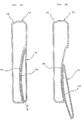
- FIG. 6A shows the auxiliary casing 70 in the contracted position while FIG. 6B shows it in the extended position.
- FIGS. 7A and 7B are fragmentary enlarged views associated with FIGS. 6A and 6B, respectively.
- the angled lug 80e of each rail member 80 is fully received in the associated lower angled recess 100b of the back plate 100, locking the rail member 80 in position.
- the casing 70 is pulled in the direction E by a force exceeding predetermined one, the lug 80e is released from the recess 100b and pressed by the back plate 100.
- the rail members 80, hook member 90 and back plate 100 which allow the auxiliary casing 70 to slide on the main casing 60 are preferably made of resin or similar material having high wear resistance and slidableness.
- FIG. 8 shows a modified form of the extendible telephone 50.
- this embodiment does not have the rail members 80, hook member 90 or back plate 100 and, instead, provides the main casing 60 with a pair of parallel wall portions 110 in close proximity to opposite edges of the slide surface 64 thereof.
- FIG. 8 shows only one of the wall portions 110 which adjoins the right side edge as viewed in FIG. 3.
- an elongate slot 110a is formed through the wall portion 110 and surrounded by a seat portion, or stepped portion, 110b.
- Projections 120 (only one is shown) are provided on the inner surface of the auxiliary casing 70 in alignment with the wall portions 110, and each mates with one of the slots 110a when the telephone 50 is assembled. Threaded holes 120a are formed in each projection 120.
- a leaf spring 130 is fastened to each projection 120 by screws 140 which are driven into the threaded holes 120a, while resting on the seat portion 110b. Since the leaf spring 130 is angled, it tends to pull the projection 120, i. e., the casing 70 toward the casing 60 when fastened to the projection 120. Therefore, the casing 70 constantly biased by the leaf spring 130 does not slide relative to the casing 60 while it is free from external forces. When the user pulls or presses the casing 70, the casing 70 is ready to slide on the casing 60.
- the slot 110a functions to delimit the slidable range of the casing 70.
- the length of the slot 110a is selected such that the casing 70 fully lies on the slide surface 64 of the casing 60 when the projection 120 abuts against one end of the slot 110a or fully extends from the casing 60 when the former abuts against the other end of the latter.
- the casings 60 and 70 may be provided with the projections 120 and the slots 110a, respectively, contrary to the above modification.
- the present invention provides an extendible telephone which is small size, light weight and highly portable, enhances the design freedom while achieving attractive appearance, simplifies the assembly, and reduces the cost.
Landscapes
- Engineering & Computer Science (AREA)
- Signal Processing (AREA)
- Telephone Set Structure (AREA)
Claims (11)
- Poste téléphonique extensible possédant un boîtier principal (60) pourvu au moins d'un récepteur (62) et d'une surface de glissement (64), et un boîtier secondaire (70) pourvu au moins d'un émetteur (72) et monté sur ledit boîtier principal afin d'être extensible à partir dudit boîtier principal selon un mouvement de glissement, ledit poste téléphonique comprenant :un élément de plaque arrière (100) fixé à l'arrière dudit boîtier secondaire (70) qui fait face à ladite surface de glissement dudit boîtier principal (60) ;des éléments de glissement (80) intervenant entre ladite surface de glissement dudit boîtier principal (60) et ledit élément de plaque arrière (100) pour permettre audit boîtier secondaire (70) de glisser par rapport audit boîtier principal (60), soit vers une position étendue, soit vers une position contractée ; etun élément de support (90) pour connecter ledit élément de plaque arrière (100) de façon glissante à ladite surface de glissement dudit boîtier principal (60), via lesdits éléments de glissement.
- Poste téléphonique selon la revendication 1, comprenant en outre une paire de rainures s'étendant selon une direction longitudinale sur ladite surface de glissement dudit boîtier principal, à proximité rapprochée de bords latéraux opposés de ladite surface de glissement et symétriquement l'une par rapport à l'autre, une paire de fentes de guidage formées à travers ledit boîtier principal parallèlement à ladite paire de rainures et plus proches desdits bords latéraux opposés que desdites rainures, et une paire de trous rectangulaires situés au-dessus et en alignement avec ladite paire de fentes de guidage.
- Poste téléphonique selon la revendication 2, dans lequel lesdits éléments de glissement ont une configuration complémentaire à la configuration de ladite paire de rainures, et comprennent chacun une partie plate, une partie bombée s'étendant selon la direction longitudinale de ladite partie plate, une oreille inclinée et située au milieu entre des extrémités opposées de ladite partie bombée, et une paire de cliquets situés aux extrémités opposées dudit élément de glissement.
- Poste téléphonique selon la revendication 3, dans lequel ledit élément de support comprend un crochet allongé possédant à ses extrémités opposées une paire de cliquets qui s'étendent à travers ladite paire de trous rectangulaires dudit boîtier principal.
- Poste téléphonique selon la revendication 4, dans lequel ledit élément de plaque arrière comprend une paire de cliquets prévus à l'arrière qui fait face à ladite surface de glissement dudit boîtier principal et s'accouplant avec et glissant dans ladite paire de fentes de guidage dudit boîtier principal, une première et une seconde paires d'évidements espacés l'un de l'autre d'une distance prédéterminée et pouvant s'engager sélectivement avec ladite paire d'oreilles inclinées desdits éléments de glissement, et une paire de rainures de guidage situées plus près des bords latéraux opposés dudit élément de plaque arrière que lesdites première et seconde paires d'évidements pour recevoir de façon glissante ladite paire de cliquets dudit crochet.
- Poste téléphonique selon la revendication 5, comprenant en outre un cliquet formé au bord inférieur de ladite surface de glissement dudit boîtier principal.
- Poste téléphonique selon la revendication 6, dans lequel ledit élément de plaque arrière comprend en outre un évidement de guidage allongé pour permettre audit cliquet dudit boîtier principal de glisser à l'intérieur de celui-ci lorsque ledit boîtier secondaire est glissé.
- Poste téléphonique selon la revendication 1, dans lequel ledit élément de plaque arrière, lesdits éléments de glissement et ledit élément de support sont fabriqués en résine ayant une haute capacité de glissement et apte à résister à l'usure.
- Poste téléphonique possédant un boîtier principal (60) pourvu au moins d'un récepteur (62), et un boîtier secondaire (70) pourvu au moins d'un émetteur (72) et monté sur ledit boîtier principal afin d'être extensible à partir dudit boîtier principal selon un mouvement de glissement, ledit poste téléphonique comprenant :une surface incurvée de glissement (64) le long de laquelle ledit boîtier secondaire peut glisser par rapport audit boîtier principal ; etdes moyens de connexion (80, 90) pour connecter de façon glissante ledit boîtier secondaire audit boîtier principal, via ladite surface de glissement.
- Poste téléphonique selon la revendication 9, dans lequel lesdits moyens de connexion comprennent des fentes formées dans l'un dudit boîtier principal et dudit boîtier secondaire pour délimiter la plage de glissement dudit boîtier secondaire par rapport audit boîtier principal, et des oreilles prévues sur l'autre dudit boîtier principal et dudit boîtier secondaire.
- Poste téléphonique selon la revendication 10, dans lequel lesdits moyens de connexion comprennent en outre des ressorts à lames maintenant chacun l'une des oreilles en engagement avec l'une associée desdites fentes.
Applications Claiming Priority (2)
| Application Number | Priority Date | Filing Date | Title |
|---|---|---|---|
| JP3057855A JP3016889B2 (ja) | 1991-02-28 | 1991-02-28 | 携帯用電話機 |
| JP57855/91 | 1991-02-28 |
Publications (3)
| Publication Number | Publication Date |
|---|---|
| EP0501820A2 EP0501820A2 (fr) | 1992-09-02 |
| EP0501820A3 EP0501820A3 (en) | 1993-01-13 |
| EP0501820B1 true EP0501820B1 (fr) | 1996-06-12 |
Family
ID=13067607
Family Applications (1)
| Application Number | Title | Priority Date | Filing Date |
|---|---|---|---|
| EP92301719A Expired - Lifetime EP0501820B1 (fr) | 1991-02-28 | 1992-02-28 | Carter de téléphone extensible |
Country Status (8)
| Country | Link |
|---|---|
| US (1) | US5335274A (fr) |
| EP (1) | EP0501820B1 (fr) |
| JP (1) | JP3016889B2 (fr) |
| KR (1) | KR960006947B1 (fr) |
| AU (1) | AU642585B2 (fr) |
| CA (1) | CA2061948C (fr) |
| DE (1) | DE69211384T2 (fr) |
| ES (1) | ES2090496T3 (fr) |
Families Citing this family (41)
| Publication number | Priority date | Publication date | Assignee | Title |
|---|---|---|---|---|
| JP2581414B2 (ja) * | 1993-10-08 | 1997-02-12 | 日本電気株式会社 | 携帯無線機 |
| JP2595932B2 (ja) * | 1994-05-18 | 1997-04-02 | 日本電気株式会社 | 携帯無線機 |
| USD370673S (en) | 1995-02-21 | 1996-06-11 | Kabushiki Kaisha Toshiba | Handheld information communications terminal |
| US5661797A (en) * | 1995-11-01 | 1997-08-26 | Nokia Mobile Phones Ltd. | Hinge mechanism for cellular transceiver housing |
| USD381020S (en) * | 1996-01-19 | 1997-07-15 | Mitsubishi Electronics America, Inc. | Telephone with slidable cover |
| US5867772A (en) * | 1996-03-08 | 1999-02-02 | Ericsson, Inc. | Cellular telephone assembly and method for assembling a cellular telephone |
| USD386757S (en) * | 1996-03-13 | 1997-11-25 | Motorola, Inc. | Portable radio communication device |
| USD406131S (en) * | 1996-10-29 | 1999-02-23 | Siemens Aktiengesellschaft | Mobile radiotelephone device |
| US5999822A (en) * | 1997-03-14 | 1999-12-07 | Sony Corporation | Cellular telephone with extendible microphone |
| US6101402A (en) * | 1997-09-04 | 2000-08-08 | Ericcson Inc. | Radiotelephone with sliding acoustic member |
| US6058293A (en) * | 1997-09-12 | 2000-05-02 | Ericsson, Inc. | Frame structure for cellular telephones |
| US6026283A (en) * | 1997-12-05 | 2000-02-15 | Ericsson Inc. | Electrically conductive keypad lightguides |
| FI112759B (fi) | 1998-03-18 | 2003-12-31 | Nokia Corp | Teleskooppipuhelin |
| US6243595B1 (en) * | 1998-06-16 | 2001-06-05 | Nortel Networks Limited | Portable wireless communication device having an extendible section |
| USD423493S (en) * | 1998-06-16 | 2000-04-25 | Sony Corporation | Wireless telephone |
| USD409601S (en) * | 1998-10-14 | 1999-05-11 | Sony Corporation | Cellular telephone with extendible keyboard |
| FI116029B (fi) * | 1998-12-22 | 2005-08-31 | Nokia Corp | Sähköisen laitteen teleskooppikuoren rakenne |
| KR100322271B1 (ko) * | 2000-03-23 | 2002-02-06 | 윤종용 | 휴대용 무선단말기의 슬라이드 키 장치 |
| USD466096S1 (en) | 2001-08-24 | 2002-11-26 | Masahiko Takada | Mobile phone with digital camera |
| USD495324S1 (en) | 2001-11-13 | 2004-08-31 | Nokia Corporation | Portion of a handset |
| USD481692S1 (en) | 2001-11-13 | 2003-11-04 | Nokia Corporation | Handset |
| USD479215S1 (en) | 2002-01-25 | 2003-09-02 | Kabushiki Kaisha Toshiba | Portable phone |
| JP2004235897A (ja) * | 2003-01-29 | 2004-08-19 | Kato Electrical Mach Co Ltd | 携帯電話機並びにスライド機構 |
| DE10314311A1 (de) * | 2003-03-31 | 2004-10-28 | Siemens Ag | Mobilfunkgerät |
| KR100563696B1 (ko) | 2003-09-09 | 2006-03-28 | 엘지전자 주식회사 | 슬라이드형 이동통신 단말기의 슬라이드 구조 |
| JP3944506B2 (ja) * | 2003-10-28 | 2007-07-11 | エルジー エレクトロニクス インコーポレイティド | スライド型携帯端末機及びそれに使用されるスライド装置 |
| KR100576000B1 (ko) * | 2003-10-29 | 2006-05-02 | 삼성전자주식회사 | 슬라이딩 타입 휴대용 단말기의 스프링 모듈 |
| KR100608726B1 (ko) * | 2003-12-09 | 2006-08-04 | 엘지전자 주식회사 | 양방향 슬라이드형 휴대용 단말기 |
| JP4034333B2 (ja) | 2004-05-31 | 2008-01-16 | 三菱電機株式会社 | 機器 |
| KR100689498B1 (ko) * | 2004-11-25 | 2007-03-02 | 삼성전자주식회사 | 슬라이딩 타입 휴대 단말기의 슬라이딩 모듈 |
| JP2006173794A (ja) * | 2004-12-13 | 2006-06-29 | Kato Electrical Mach Co Ltd | 携帯機器のスライド機構及び携帯電話機 |
| DE602004018204D1 (de) * | 2004-12-20 | 2009-01-15 | Nokia Corp | Elektronische einrichtung |
| JP4530218B2 (ja) * | 2005-03-07 | 2010-08-25 | ソニー・エリクソン・モバイルコミュニケーションズ株式会社 | 携帯端末装置 |
| EP1867143B1 (fr) * | 2005-04-06 | 2011-11-02 | Nokia Corporation | Dispositif electronique mobile extensible |
| US20070155447A1 (en) * | 2005-12-29 | 2007-07-05 | Gordecki Ryszard J | Sliding motion arrangement for electronic devices |
| US7653422B2 (en) * | 2006-02-28 | 2010-01-26 | Motorola, Inc. | Method and apparatus for a sliding hinge |
| TWI387427B (zh) * | 2009-01-22 | 2013-02-21 | Asustek Comp Inc | 手持電子裝置 |
| CN201426224Y (zh) * | 2009-06-05 | 2010-03-17 | 新日兴股份有限公司 | 滑动式枢纽器以及具有滑动式枢纽器的电子装置 |
| TWM388826U (en) * | 2010-04-30 | 2010-09-11 | Hon Hai Prec Ind Co Ltd | Sliding apparatus |
| JP2012191557A (ja) * | 2011-03-14 | 2012-10-04 | Panasonic Corp | 電子機器 |
| KR102866878B1 (ko) | 2020-05-08 | 2025-10-01 | 삼성디스플레이 주식회사 | 표시 장치 |
Family Cites Families (7)
| Publication number | Priority date | Publication date | Assignee | Title |
|---|---|---|---|---|
| US4272655A (en) * | 1979-08-22 | 1981-06-09 | International Telephone And Telegraph Corporation | Compact telephone set employing slidable actuated supervision switches |
| DE3323858A1 (de) * | 1983-07-01 | 1985-01-03 | Erwin Brandenstein | Schnurloses fernsprechgeraet |
| US4821318A (en) * | 1987-04-17 | 1989-04-11 | Wu Chuan Chi | Convertible handset device for telephone sets |
| US4907266A (en) * | 1988-05-24 | 1990-03-06 | Chen Ping Huang | Headphone-convertible telephone hand set |
| DE3836406A1 (de) * | 1988-10-26 | 1990-05-03 | Bosch Gmbh Robert | Handapparatfoermiges funkbedienteil |
| US5003589A (en) * | 1989-06-01 | 1991-03-26 | Chen Ping Huang | Headphone-convertible telephone handset |
| US5054051A (en) * | 1990-01-31 | 1991-10-01 | At&E Corporation | Autodial from database in an electronic wristwatch |
-
1991
- 1991-02-28 JP JP3057855A patent/JP3016889B2/ja not_active Expired - Fee Related
-
1992
- 1992-02-27 CA CA002061948A patent/CA2061948C/fr not_active Expired - Fee Related
- 1992-02-27 AU AU11294/92A patent/AU642585B2/en not_active Ceased
- 1992-02-28 US US07/843,460 patent/US5335274A/en not_active Expired - Lifetime
- 1992-02-28 KR KR1019920003199A patent/KR960006947B1/ko not_active Expired - Fee Related
- 1992-02-28 DE DE69211384T patent/DE69211384T2/de not_active Expired - Fee Related
- 1992-02-28 EP EP92301719A patent/EP0501820B1/fr not_active Expired - Lifetime
- 1992-02-28 ES ES92301719T patent/ES2090496T3/es not_active Expired - Lifetime
Also Published As
| Publication number | Publication date |
|---|---|
| EP0501820A2 (fr) | 1992-09-02 |
| EP0501820A3 (en) | 1993-01-13 |
| DE69211384D1 (de) | 1996-07-18 |
| ES2090496T3 (es) | 1996-10-16 |
| US5335274A (en) | 1994-08-02 |
| JPH04273744A (ja) | 1992-09-29 |
| AU642585B2 (en) | 1993-10-21 |
| KR960006947B1 (ko) | 1996-05-25 |
| AU1129492A (en) | 1992-09-03 |
| JP3016889B2 (ja) | 2000-03-06 |
| CA2061948C (fr) | 1996-02-20 |
| KR920017411A (ko) | 1992-09-26 |
| DE69211384T2 (de) | 1996-11-07 |
| CA2061948A1 (fr) | 1992-08-29 |
Similar Documents
| Publication | Publication Date | Title |
|---|---|---|
| EP0501820B1 (fr) | Carter de téléphone extensible | |
| US5987122A (en) | Portable phone with cover actuating hinge assembly | |
| US6314274B1 (en) | Portable radio having retractable keys, wherein the keys retract within the housing upon movement of a retraction accuator | |
| US5185790A (en) | Multiposition detenting hinge apparatus | |
| US6463262B1 (en) | Radio telephone | |
| US20050288055A1 (en) | Electronic equipment comprising a retractable screen | |
| US20050197173A1 (en) | Pop-up type portable terminal | |
| US20050202856A1 (en) | Swing-type portable terminal | |
| EP0692899A2 (fr) | Appareil de téléphonie sans fil portable et pliable | |
| KR20040093517A (ko) | 원 스텝 자동 힌지 장치 및 그를 구비하는 정보 단말기 | |
| US7124472B2 (en) | Hinge mechanism with single hand operation | |
| US6324386B1 (en) | Folding communication device | |
| EP1703705B1 (fr) | Module coulissant pour un terminal de communication portable | |
| US7383617B2 (en) | Hinge assembly | |
| EP1783983B1 (fr) | Module coulissant pour un terminal mobile | |
| KR20010034639A (ko) | 이동 전화기의 플립 힌지 장치 | |
| US7751187B2 (en) | Foldable electronic device | |
| KR100713421B1 (ko) | 휴대용 단말기의 슬라이딩 모듈 | |
| EP1898603B1 (fr) | Terminal portable de type coulissant | |
| EP1970793B1 (fr) | Terminal portable comportant un module à glissière | |
| GB2325372A (en) | Two part flip cover for a portable telephone | |
| EP0735698A2 (fr) | Téléphone portable pliable avec extension de l'écouteur au déploiement du boîtier du téléphone | |
| EP1734725B1 (fr) | Terminal portable avec module de coulissement | |
| KR20040006978A (ko) | 슬라이딩 타입 휴대용 무선 단말기 | |
| JPH05244238A (ja) | 伸縮型電話機 |
Legal Events
| Date | Code | Title | Description |
|---|---|---|---|
| PUAI | Public reference made under article 153(3) epc to a published international application that has entered the european phase |
Free format text: ORIGINAL CODE: 0009012 |
|
| 17P | Request for examination filed |
Effective date: 19920313 |
|
| AK | Designated contracting states |
Kind code of ref document: A2 Designated state(s): DE ES FR GB IT NL SE |
|
| PUAL | Search report despatched |
Free format text: ORIGINAL CODE: 0009013 |
|
| AK | Designated contracting states |
Kind code of ref document: A3 Designated state(s): DE ES FR GB IT NL SE |
|
| 17Q | First examination report despatched |
Effective date: 19950515 |
|
| RAP1 | Party data changed (applicant data changed or rights of an application transferred) |
Owner name: NTT MOBILE COMMUNICATIONS NETWORK INC. Owner name: NIPPON TELEGRAPH AND TELEPHONE CORPORATION Owner name: NEC CORPORATION |
|
| GRAA | (expected) grant |
Free format text: ORIGINAL CODE: 0009210 |
|
| AK | Designated contracting states |
Kind code of ref document: B1 Designated state(s): DE ES FR GB IT NL SE |
|
| REF | Corresponds to: |
Ref document number: 69211384 Country of ref document: DE Date of ref document: 19960718 |
|
| ITF | It: translation for a ep patent filed | ||
| ET | Fr: translation filed | ||
| REG | Reference to a national code |
Ref country code: ES Ref legal event code: FG2A Ref document number: 2090496 Country of ref document: ES Kind code of ref document: T3 |
|
| REG | Reference to a national code |
Ref country code: ES Ref legal event code: FG2A Ref document number: 2090496 Country of ref document: ES Kind code of ref document: T3 |
|
| PLBE | No opposition filed within time limit |
Free format text: ORIGINAL CODE: 0009261 |
|
| 26N | No opposition filed | ||
| PGFP | Annual fee paid to national office [announced via postgrant information from national office to epo] |
Ref country code: GB Payment date: 19971204 Year of fee payment: 7 |
|
| PGFP | Annual fee paid to national office [announced via postgrant information from national office to epo] |
Ref country code: FR Payment date: 19990209 Year of fee payment: 8 |
|
| PGFP | Annual fee paid to national office [announced via postgrant information from national office to epo] |
Ref country code: SE Payment date: 19990218 Year of fee payment: 8 |
|
| PGFP | Annual fee paid to national office [announced via postgrant information from national office to epo] |
Ref country code: NL Payment date: 19990224 Year of fee payment: 8 |
|
| PG25 | Lapsed in a contracting state [announced via postgrant information from national office to epo] |
Ref country code: GB Free format text: LAPSE BECAUSE OF NON-PAYMENT OF DUE FEES Effective date: 19990228 |
|
| PGFP | Annual fee paid to national office [announced via postgrant information from national office to epo] |
Ref country code: DE Payment date: 19990305 Year of fee payment: 8 |
|
| GBPC | Gb: european patent ceased through non-payment of renewal fee |
Effective date: 19990228 |
|
| PGFP | Annual fee paid to national office [announced via postgrant information from national office to epo] |
Ref country code: ES Payment date: 20000218 Year of fee payment: 9 |
|
| PG25 | Lapsed in a contracting state [announced via postgrant information from national office to epo] |
Ref country code: SE Free format text: LAPSE BECAUSE OF NON-PAYMENT OF DUE FEES Effective date: 20000301 |
|
| PG25 | Lapsed in a contracting state [announced via postgrant information from national office to epo] |
Ref country code: NL Free format text: LAPSE BECAUSE OF NON-PAYMENT OF DUE FEES Effective date: 20000901 |
|
| PG25 | Lapsed in a contracting state [announced via postgrant information from national office to epo] |
Ref country code: FR Free format text: LAPSE BECAUSE OF NON-PAYMENT OF DUE FEES Effective date: 20001031 |
|
| NLV4 | Nl: lapsed or anulled due to non-payment of the annual fee |
Effective date: 20000901 |
|
| EUG | Se: european patent has lapsed |
Ref document number: 92301719.8 |
|
| PG25 | Lapsed in a contracting state [announced via postgrant information from national office to epo] |
Ref country code: DE Free format text: LAPSE BECAUSE OF NON-PAYMENT OF DUE FEES Effective date: 20001201 |
|
| REG | Reference to a national code |
Ref country code: FR Ref legal event code: ST |
|
| PG25 | Lapsed in a contracting state [announced via postgrant information from national office to epo] |
Ref country code: ES Free format text: LAPSE BECAUSE OF NON-PAYMENT OF DUE FEES Effective date: 20010301 |
|
| REG | Reference to a national code |
Ref country code: ES Ref legal event code: FD2A Effective date: 20020916 |
|
| PG25 | Lapsed in a contracting state [announced via postgrant information from national office to epo] |
Ref country code: IT Free format text: LAPSE BECAUSE OF NON-PAYMENT OF DUE FEES;WARNING: LAPSES OF ITALIAN PATENTS WITH EFFECTIVE DATE BEFORE 2007 MAY HAVE OCCURRED AT ANY TIME BEFORE 2007. THE CORRECT EFFECTIVE DATE MAY BE DIFFERENT FROM THE ONE RECORDED. Effective date: 20050228 |