EP0501845A1 - Betätigungseinrichtung eines Getriebes - Google Patents
Betätigungseinrichtung eines Getriebes Download PDFInfo
- Publication number
- EP0501845A1 EP0501845A1 EP92400327A EP92400327A EP0501845A1 EP 0501845 A1 EP0501845 A1 EP 0501845A1 EP 92400327 A EP92400327 A EP 92400327A EP 92400327 A EP92400327 A EP 92400327A EP 0501845 A1 EP0501845 A1 EP 0501845A1
- Authority
- EP
- European Patent Office
- Prior art keywords
- control
- finger
- rocker
- axis
- synchronizer
- Prior art date
- Legal status (The legal status is an assumption and is not a legal conclusion. Google has not performed a legal analysis and makes no representation as to the accuracy of the status listed.)
- Granted
Links
- 238000006073 displacement reaction Methods 0.000 claims description 3
- 230000003993 interaction Effects 0.000 abstract 1
- 230000000694 effects Effects 0.000 description 3
- 238000005336 cracking Methods 0.000 description 2
- 230000007935 neutral effect Effects 0.000 description 2
- 230000004308 accommodation Effects 0.000 description 1
- 238000006243 chemical reaction Methods 0.000 description 1
- 238000012423 maintenance Methods 0.000 description 1
Images


Classifications
-
- F—MECHANICAL ENGINEERING; LIGHTING; HEATING; WEAPONS; BLASTING
- F16—ENGINEERING ELEMENTS AND UNITS; GENERAL MEASURES FOR PRODUCING AND MAINTAINING EFFECTIVE FUNCTIONING OF MACHINES OR INSTALLATIONS; THERMAL INSULATION IN GENERAL
- F16H—GEARING
- F16H63/00—Control outputs from the control unit to change-speed- or reversing-gearings for conveying rotary motion or to other devices than the final output mechanism
- F16H63/02—Final output mechanisms therefor; Actuating means for the final output mechanisms
- F16H63/30—Constructional features of the final output mechanisms
- F16H63/302—Final output mechanisms for reversing
-
- F—MECHANICAL ENGINEERING; LIGHTING; HEATING; WEAPONS; BLASTING
- F16—ENGINEERING ELEMENTS AND UNITS; GENERAL MEASURES FOR PRODUCING AND MAINTAINING EFFECTIVE FUNCTIONING OF MACHINES OR INSTALLATIONS; THERMAL INSULATION IN GENERAL
- F16H—GEARING
- F16H3/00—Toothed gearings for conveying rotary motion with variable gear ratio or for reversing rotary motion
- F16H3/02—Toothed gearings for conveying rotary motion with variable gear ratio or for reversing rotary motion without gears having orbital motion
- F16H3/20—Toothed gearings for conveying rotary motion with variable gear ratio or for reversing rotary motion without gears having orbital motion exclusively or essentially using gears that can be moved out of gear
- F16H3/38—Toothed gearings for conveying rotary motion with variable gear ratio or for reversing rotary motion without gears having orbital motion exclusively or essentially using gears that can be moved out of gear with synchro-meshing
- F16H3/385—Toothed gearings for conveying rotary motion with variable gear ratio or for reversing rotary motion without gears having orbital motion exclusively or essentially using gears that can be moved out of gear with synchro-meshing with braking means
-
- F—MECHANICAL ENGINEERING; LIGHTING; HEATING; WEAPONS; BLASTING
- F16—ENGINEERING ELEMENTS AND UNITS; GENERAL MEASURES FOR PRODUCING AND MAINTAINING EFFECTIVE FUNCTIONING OF MACHINES OR INSTALLATIONS; THERMAL INSULATION IN GENERAL
- F16H—GEARING
- F16H63/00—Control outputs from the control unit to change-speed- or reversing-gearings for conveying rotary motion or to other devices than the final output mechanism
- F16H63/02—Final output mechanisms therefor; Actuating means for the final output mechanisms
- F16H63/08—Multiple final output mechanisms being moved by a single common final actuating mechanism
- F16H63/20—Multiple final output mechanisms being moved by a single common final actuating mechanism with preselection and subsequent movement of each final output mechanism by movement of the final actuating mechanism in two different ways, e.g. guided by a shift gate
- F16H2063/208—Multiple final output mechanisms being moved by a single common final actuating mechanism with preselection and subsequent movement of each final output mechanism by movement of the final actuating mechanism in two different ways, e.g. guided by a shift gate using two or more selecting fingers
-
- F—MECHANICAL ENGINEERING; LIGHTING; HEATING; WEAPONS; BLASTING
- F16—ENGINEERING ELEMENTS AND UNITS; GENERAL MEASURES FOR PRODUCING AND MAINTAINING EFFECTIVE FUNCTIONING OF MACHINES OR INSTALLATIONS; THERMAL INSULATION IN GENERAL
- F16H—GEARING
- F16H63/00—Control outputs from the control unit to change-speed- or reversing-gearings for conveying rotary motion or to other devices than the final output mechanism
- F16H63/02—Final output mechanisms therefor; Actuating means for the final output mechanisms
- F16H63/30—Constructional features of the final output mechanisms
- F16H2063/3086—Shift head arrangements, e.g. forms or arrangements of shift heads for preselection or shifting
-
- F—MECHANICAL ENGINEERING; LIGHTING; HEATING; WEAPONS; BLASTING
- F16—ENGINEERING ELEMENTS AND UNITS; GENERAL MEASURES FOR PRODUCING AND MAINTAINING EFFECTIVE FUNCTIONING OF MACHINES OR INSTALLATIONS; THERMAL INSULATION IN GENERAL
- F16H—GEARING
- F16H63/00—Control outputs from the control unit to change-speed- or reversing-gearings for conveying rotary motion or to other devices than the final output mechanism
- F16H63/02—Final output mechanisms therefor; Actuating means for the final output mechanisms
- F16H63/30—Constructional features of the final output mechanisms
- F16H63/32—Gear shift yokes, e.g. shift forks
- F16H2063/325—Rocker or swiveling forks, i.e. the forks are pivoted in the gear case when moving the sleeve
Definitions
- the present invention relates to a device for controlling a gearbox of a motor vehicle.
- the most logical solution for the design of such an arrangement consists in actuating one of the forward synchronizers before the engagement of the reverse gear. , and preferably the synchronizer associated with the highest rank ratio which has a lower inertia.
- the fifth speed synchronizer is first actuated to slow the primary shaft and then released.
- the slowing down of the primary shaft must be released before the teeth come into contact to allow the teeth to coincide so as not to hinder the final engagement phase.
- the document FR-A-2,263,428 describes an arrangement of simple design resulting from the fact that the upper fourth gear is arranged next to the reverse gear, and not in face, the reverse gear itself being controlled by an axis parallel to the third-fourth control axis.
- the solution described in this document therefore does not solve the problem mentioned above.
- This arrangement has many disadvantages due in particular to the fact that it is necessary to provide an extension of the rocker to receive one of the cams which is particularly bulky. It is also particularly difficult to ensure precise positioning of the two cams relative to one another.
- the object of the invention is to propose a device for controlling a gearbox of a motor vehicle. which solves the problem mentioned above while avoiding the drawbacks inherent in the device known from the prior art.
- the invention proposes a device for controlling a motor vehicle gearbox of the type comprising a control member movable in axial translation and in rotation about its axis perpendicular to the primary and secondary shafts of the gearbox for , starting from a determined axial position of selection, causing by rotation in a first direction the engagement without synchronizer of the reverse gear ratio by cooperation of the end of the reverse control finger with a reverse grip formed at the end of a rocker which pivots about a fixed axis perpendicular to the primary and secondary shafts, and of the type comprising means for braking the gears of the gearbox before engagement of the reverse gear ratio by cooperation of the engagement members of this ratio with actuating elements of a synchronizer associated with one of the forward gears of the gearbox e of gears, characterized in that said actuating elements comprise a synchronizer control fork linked in axial translation to a control axis parallel to the primary and secondary shafts and a drive arm of the fork control axis linked in translation to
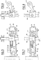
- the control member 10 receives a control part 14 which is linked to it in translation and in rotation.
- the control part 14 has two control fingers 16 and 18.
- the control finger 16 as a function of the axial position occupied by the control member 12, is capable of being received in a stock 20 for controlling the first and second forward gear ratios, in a stock 22 for controlling the third and fourth forward gear, that is to say in the position in which it is illustrated in FIG. 1, or finally in a stock 24 for controlling the reverse gear.
- the sticks 20 and 22 are respectively associated with the sliding axes 26 and 28 which carry the forks for controlling the corresponding forward gear ratios.
- the axes 26 and 28 are perpendicular to the X-X axis.
- the reverse stock 24 is formed at a free end of a reverse control rocker 32 which is pivotally mounted by means of an axis 34 around a geometric axis YY which is perpendicular to the axis XX as well as the axes of the primary 36 and secondary shafts of the gearbox.
- the end of the rocker 32 opposite to the butt 24 comprises a fork 38 which acts directly on the sliding gear 40 of reverse gear mounted on its axis 42.
- the second control finger 18 is engaged in a stock 44 for controlling the fifth forward gear.
- the butt 44 is formed on a part 46 also called fifth nut which is linked in translation and in rotation to an axis 48 slidably mounted in the casing 10 and which carries, at its free end 50 the fork 52 which acts on the sleeve 53 of the synchronizer 54 of the pinion 56 of the fifth forward gear.
- the axis 48 is parallel to the primary and secondary shafts and is perpendicular to the control member 12 and to the axis Y-Y of pivoting of the rocker 32.
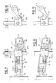
- a first lateral face 60 is a continuous flat surface while the opposite lateral face is a surface comprising two parallel portions 61 and 63, the first of which extends over a reduced height relative to that of the lateral face 60 and then extends , offset by the portion 63.
- the nut 46 has an extension 62 which constitutes the drive arm of the axis 48 by means of the rocker 32.
- the arm 62 receives at its end a retractable ball 64 which is slidably mounted in a cylindrical hole 66 and is resiliently urged by a spring 68 in the direction of a ramp 70 formed opposite an extension 71 of the rocker 32.
- the drive arm 62 extends opposite the butt 24 relative to the axis 48.
- the various components of the control device illustrated in Figures 1 to 3 are shown in the so-called neutral position.
- the fork 38 of the rocker 32 freely overlaps the player 40. There is a clearance between the ball 64 and the inclined portion 74 of the ramp 70.
- the fork 52 for controlling the sleeve 53 of the synchronizer 54 is therefore not stressed axially and the synchronizer does not perform any synchronization function.
- FIGS. 7 and 8 The first phase of engagement of the market report reverse gear is illustrated in FIGS. 7 and 8.
- the driver transmits a passing movement by means of the control member 12 which causes the simultaneous rotation of the two control fingers 16 and 18 counterclockwise by considering Figures 2 and 8.
- This rotation has firstly the effect of bringing the end of the control finger 16 to bear against the face opposite the butt 24 of the reverse rocker 32 to cause the latter to pivot about its axis YY clockwise considering figure 7.
- This drive is transmitted by the axis 48 to the fork 52 and therefore to the sleeve 53 of the synchronizer 54.
- This action has the effect of bringing the friction cone of the synchronizer into contact and therefore of causing the shaft to brake or slow down. gearbox primary.
- the movement of the drive arm 62 and the axis 48 in the direction D1 is interrupted as soon as the free end 58 of the control finger 18 abuts against the upper portion 63 of the face opposite lacrosse 44.
- the axis 48 and the fork 50 no longer exert any force on the sleeve 53 of the synchronizer 54.
- the prior release of the latter is ensured positively due to the presence of another inclined portion 76 of the ramp 70 which cooperates with the ball 64 to confirm the movement of the nut 46 and the axis 48 in the direction D2.
- Another solution consists in using an extension 84 formed on the nut 46 to cooperate with a vis-à-vis abutment 86 formed directly on the rocker 32. Thanks to this arrangement, the interlocking between the rocker 32 and the nut is carried out directly. 46.
- a fixed stop 90 or 91 provided at the synchronizer 54 provides an axial reaction effect on the axis 48 to allow crossing of the portion 76 of the ramp 40 by the ball 64.
Landscapes
- Engineering & Computer Science (AREA)
- General Engineering & Computer Science (AREA)
- Mechanical Engineering (AREA)
- Gear-Shifting Mechanisms (AREA)
- Mechanical Operated Clutches (AREA)
- Control Of Transmission Device (AREA)
Applications Claiming Priority (2)
| Application Number | Priority Date | Filing Date | Title |
|---|---|---|---|
| FR919102224A FR2673254B1 (fr) | 1991-02-25 | 1991-02-25 | Dispositif de commande d'une boite de vitesses. |
| FR9102224 | 1991-02-25 |
Publications (2)
| Publication Number | Publication Date |
|---|---|
| EP0501845A1 true EP0501845A1 (de) | 1992-09-02 |
| EP0501845B1 EP0501845B1 (de) | 1994-12-14 |
Family
ID=9410061
Family Applications (1)
| Application Number | Title | Priority Date | Filing Date |
|---|---|---|---|
| EP92400327A Expired - Lifetime EP0501845B1 (de) | 1991-02-25 | 1992-02-07 | Betätigungseinrichtung eines Getriebes |
Country Status (4)
| Country | Link |
|---|---|
| EP (1) | EP0501845B1 (de) |
| JP (1) | JPH04312263A (de) |
| DE (1) | DE69200867T2 (de) |
| FR (1) | FR2673254B1 (de) |
Cited By (7)
| Publication number | Priority date | Publication date | Assignee | Title |
|---|---|---|---|---|
| FR2702263A1 (fr) * | 1993-03-02 | 1994-09-09 | Peugeot | Dispositif de commande d'une boîte de vitesses. |
| FR2724002A1 (fr) * | 1994-08-31 | 1996-03-01 | Peugeot | Dispositif perfectionne de commande d'une boite de vitesses de vehicule automobile |
| EP0674125A3 (de) * | 1994-03-23 | 1997-04-23 | Ford Werke Ag | Vorrichtung zur Betätigung der Synchronisation eines Vorwärtsganges beim Einlegen eines Rückwärtsganges. |
| EP0745790B1 (de) * | 1995-05-29 | 2000-03-08 | Automobiles Peugeot | Interne Steuerung eines Fahrzeug-Schaltgetriebes mit einer Zahnrad-Bremsvorrichtung |
| FR2815104A1 (fr) * | 2000-10-11 | 2002-04-12 | Renault | Boite de vitesse manuelle avec frein de marche arriere |
| EP1209382A1 (de) * | 2000-11-22 | 2002-05-29 | FIAT AUTO S.p.A. | Wendegetriebe für Gangwahl- und Schaltsteuerung in einem Kraftfahrzeuggetriebe |
| EP2050988A1 (de) * | 2007-10-17 | 2009-04-22 | Peugeot Citroen Automobiles SA | Bremsvorrichtung einer Motorwelle in einem Getriebe zum Einrücken eines Rückwärtsgangrads |
Families Citing this family (4)
| Publication number | Priority date | Publication date | Assignee | Title |
|---|---|---|---|---|
| DE19911805A1 (de) | 1999-03-17 | 2000-09-28 | Bosch Gmbh Robert | Spritzvorrichtung für eine Scheibenwaschanlage |
| KR100402077B1 (ko) * | 2000-11-02 | 2003-10-17 | 현대자동차주식회사 | 수동변속기용 변속조작기구 |
| DE10253471A1 (de) * | 2002-11-16 | 2004-08-26 | Zf Friedrichshafen Ag | Schaltvorrichtung für ein Getriebe |
| KR100587704B1 (ko) * | 2004-06-21 | 2006-06-09 | 현대자동차주식회사 | 수동변속기의 변속조작기구 |
Citations (3)
| Publication number | Priority date | Publication date | Assignee | Title |
|---|---|---|---|---|
| US4510818A (en) * | 1982-11-19 | 1985-04-16 | Toyota Jidosha Kabushiki Kaisha | Device for preventing reverse gear buzzing in a manual transmission |
| GB2174465A (en) * | 1985-04-24 | 1986-11-05 | Honda Motor Co Ltd | Gear-change apparatus for vehicle transmission |
| EP0300843A1 (de) * | 1987-07-20 | 1989-01-25 | Automobiles Peugeot | Zahnradbremsvorrichtung eines Fahrzeuggetriebes |
-
1991
- 1991-02-25 FR FR919102224A patent/FR2673254B1/fr not_active Expired - Fee Related
-
1992
- 1992-02-07 DE DE69200867T patent/DE69200867T2/de not_active Expired - Fee Related
- 1992-02-07 EP EP92400327A patent/EP0501845B1/de not_active Expired - Lifetime
- 1992-02-25 JP JP4037696A patent/JPH04312263A/ja active Pending
Patent Citations (3)
| Publication number | Priority date | Publication date | Assignee | Title |
|---|---|---|---|---|
| US4510818A (en) * | 1982-11-19 | 1985-04-16 | Toyota Jidosha Kabushiki Kaisha | Device for preventing reverse gear buzzing in a manual transmission |
| GB2174465A (en) * | 1985-04-24 | 1986-11-05 | Honda Motor Co Ltd | Gear-change apparatus for vehicle transmission |
| EP0300843A1 (de) * | 1987-07-20 | 1989-01-25 | Automobiles Peugeot | Zahnradbremsvorrichtung eines Fahrzeuggetriebes |
Cited By (9)
| Publication number | Priority date | Publication date | Assignee | Title |
|---|---|---|---|---|
| FR2702263A1 (fr) * | 1993-03-02 | 1994-09-09 | Peugeot | Dispositif de commande d'une boîte de vitesses. |
| EP0674125A3 (de) * | 1994-03-23 | 1997-04-23 | Ford Werke Ag | Vorrichtung zur Betätigung der Synchronisation eines Vorwärtsganges beim Einlegen eines Rückwärtsganges. |
| FR2724002A1 (fr) * | 1994-08-31 | 1996-03-01 | Peugeot | Dispositif perfectionne de commande d'une boite de vitesses de vehicule automobile |
| EP0699855A1 (de) * | 1994-08-31 | 1996-03-06 | Automobiles Peugeot | Schaltungseinrichtung für das Stufengetriebe eines Kraftfahrzeugs |
| EP0745790B1 (de) * | 1995-05-29 | 2000-03-08 | Automobiles Peugeot | Interne Steuerung eines Fahrzeug-Schaltgetriebes mit einer Zahnrad-Bremsvorrichtung |
| FR2815104A1 (fr) * | 2000-10-11 | 2002-04-12 | Renault | Boite de vitesse manuelle avec frein de marche arriere |
| EP1209382A1 (de) * | 2000-11-22 | 2002-05-29 | FIAT AUTO S.p.A. | Wendegetriebe für Gangwahl- und Schaltsteuerung in einem Kraftfahrzeuggetriebe |
| EP2050988A1 (de) * | 2007-10-17 | 2009-04-22 | Peugeot Citroen Automobiles SA | Bremsvorrichtung einer Motorwelle in einem Getriebe zum Einrücken eines Rückwärtsgangrads |
| FR2922622A1 (fr) * | 2007-10-17 | 2009-04-24 | Peugeot Citroen Automobiles Sa | Dispositif de freinage d'un arbre moteur d'une boite de vitesses, pour l'engagement d'un pignon de marche arriere |
Also Published As
| Publication number | Publication date |
|---|---|
| JPH04312263A (ja) | 1992-11-04 |
| DE69200867T2 (de) | 1995-05-04 |
| DE69200867D1 (de) | 1995-01-26 |
| FR2673254A1 (fr) | 1992-08-28 |
| EP0501845B1 (de) | 1994-12-14 |
| FR2673254B1 (fr) | 1994-03-04 |
Similar Documents
| Publication | Publication Date | Title |
|---|---|---|
| EP0293288B1 (de) | Steuervorrichtung eines Fahrzeuggetriebes | |
| EP0501845B1 (de) | Betätigungseinrichtung eines Getriebes | |
| EP0300843B1 (de) | Zahnradbremsvorrichtung eines Fahrzeuggetriebes | |
| EP0745790B1 (de) | Interne Steuerung eines Fahrzeug-Schaltgetriebes mit einer Zahnrad-Bremsvorrichtung | |
| EP3063435B1 (de) | Handschaltgetriebe eines fahrzeugs mit einer klinke zur steuerung der rückwärtsgangbremse | |
| FR2651849A1 (fr) | Dispositif de commande d'une boite de vitesses de vehicule automobile. | |
| EP1643168B1 (de) | Getriebesteuerungseinrichtung für Kraftahrzeuge | |
| EP2199647B1 (de) | Handschaltgetriebe mit einer Synchronisiereinrichtung für den Rückwärtsgang | |
| EP0699855B1 (de) | Schaltungseinrichtung für das Stufengetriebe eines Kraftfahrzeugs | |
| WO1996023995A1 (fr) | Dispositif de commande d'une boite de vitesse | |
| WO1996023995A9 (fr) | Dispositif de commande d'une boite de vitesse | |
| FR2703422A1 (fr) | Dispositif de changement de vitesses pour une boîte de vitesses à engrenages d'un véhicule automobile. | |
| FR2702263A1 (fr) | Dispositif de commande d'une boîte de vitesses. | |
| EP1022495B1 (de) | Wechselgetriebe mit synchronisiertem Rückwärtsgang | |
| EP2273158B1 (de) | Steuersystem für Getriebe | |
| FR2686669A1 (fr) | Dispositif de commande d'une boite de vitesses. | |
| EP0486349B1 (de) | Betätigungseinrichtung eines Kraftfahrzeuggetriebes | |
| EP0859922A1 (de) | Sicherheitseinrichtung für mechanisches schaltgetriebe | |
| EP0716252B1 (de) | Steuereinrichutng für ein Schaltgetriebe | |
| EP1072824A1 (de) | Getriebe kompakter Bauart mit Schwenkfüssen zur Betätigung von Schaltgabeln | |
| FR2714704A1 (fr) | Dispositif de commande d'une boîte de vitesses. | |
| EP2050988B1 (de) | Bremsvorrichtung einer Motorwelle in einem Getriebe zum Einrücken eines Rückwärtsgangrads | |
| EP2372198B1 (de) | Steuersystem für Getriebe, Steueranordnung mit einem solchen Steuersystem und Fahrzeug | |
| FR2797018A1 (fr) | Boite de vitesses compacte | |
| FR2661724A1 (fr) | Boite de vitesses pour vehicule, a commande perfectionnee. |
Legal Events
| Date | Code | Title | Description |
|---|---|---|---|
| PUAI | Public reference made under article 153(3) epc to a published international application that has entered the european phase |
Free format text: ORIGINAL CODE: 0009012 |
|
| 17P | Request for examination filed |
Effective date: 19920706 |
|
| AK | Designated contracting states |
Kind code of ref document: A1 Designated state(s): DE GB IT |
|
| 17Q | First examination report despatched |
Effective date: 19940222 |
|
| GRAA | (expected) grant |
Free format text: ORIGINAL CODE: 0009210 |
|
| AK | Designated contracting states |
Kind code of ref document: B1 Designated state(s): DE GB IT |
|
| ITF | It: translation for a ep patent filed | ||
| REF | Corresponds to: |
Ref document number: 69200867 Country of ref document: DE Date of ref document: 19950126 |
|
| GBT | Gb: translation of ep patent filed (gb section 77(6)(a)/1977) |
Effective date: 19950111 |
|
| PLBE | No opposition filed within time limit |
Free format text: ORIGINAL CODE: 0009261 |
|
| STAA | Information on the status of an ep patent application or granted ep patent |
Free format text: STATUS: NO OPPOSITION FILED WITHIN TIME LIMIT |
|
| 26N | No opposition filed | ||
| PGFP | Annual fee paid to national office [announced via postgrant information from national office to epo] |
Ref country code: DE Payment date: 19970124 Year of fee payment: 6 |
|
| PGFP | Annual fee paid to national office [announced via postgrant information from national office to epo] |
Ref country code: GB Payment date: 19980130 Year of fee payment: 7 |
|
| PG25 | Lapsed in a contracting state [announced via postgrant information from national office to epo] |
Ref country code: DE Free format text: LAPSE BECAUSE OF NON-PAYMENT OF DUE FEES Effective date: 19981103 |
|
| PG25 | Lapsed in a contracting state [announced via postgrant information from national office to epo] |
Ref country code: GB Free format text: LAPSE BECAUSE OF NON-PAYMENT OF DUE FEES Effective date: 19990207 |
|
| GBPC | Gb: european patent ceased through non-payment of renewal fee |
Effective date: 19990207 |
|
| PG25 | Lapsed in a contracting state [announced via postgrant information from national office to epo] |
Ref country code: IT Free format text: LAPSE BECAUSE OF NON-PAYMENT OF DUE FEES;WARNING: LAPSES OF ITALIAN PATENTS WITH EFFECTIVE DATE BEFORE 2007 MAY HAVE OCCURRED AT ANY TIME BEFORE 2007. THE CORRECT EFFECTIVE DATE MAY BE DIFFERENT FROM THE ONE RECORDED. Effective date: 20050207 |