EP0501988B1 - Speicherung des kontrollsignals für digitale bildzusammensetzung - Google Patents
Speicherung des kontrollsignals für digitale bildzusammensetzung Download PDFInfo
- Publication number
- EP0501988B1 EP0501988B1 EP90916506A EP90916506A EP0501988B1 EP 0501988 B1 EP0501988 B1 EP 0501988B1 EP 90916506 A EP90916506 A EP 90916506A EP 90916506 A EP90916506 A EP 90916506A EP 0501988 B1 EP0501988 B1 EP 0501988B1
- Authority
- EP
- European Patent Office
- Prior art keywords
- control plane
- video signal
- pixel
- data
- signal
- Prior art date
- Legal status (The legal status is an assumption and is not a legal conclusion. Google has not performed a legal analysis and makes no representation as to the accuracy of the status listed.)
- Expired - Lifetime
Links
- 239000000203 mixture Substances 0.000 title claims abstract description 13
- 238000000034 method Methods 0.000 claims description 8
- 230000001419 dependent effect Effects 0.000 claims 2
- 230000005540 biological transmission Effects 0.000 description 6
- 238000012935 Averaging Methods 0.000 description 3
- 238000013500 data storage Methods 0.000 description 2
- 239000002131 composite material Substances 0.000 description 1
- 230000001934 delay Effects 0.000 description 1
- 238000004519 manufacturing process Methods 0.000 description 1
- 230000007704 transition Effects 0.000 description 1
Images


Classifications
-
- H—ELECTRICITY
- H04—ELECTRIC COMMUNICATION TECHNIQUE
- H04N—PICTORIAL COMMUNICATION, e.g. TELEVISION
- H04N5/00—Details of television systems
- H04N5/222—Studio circuitry; Studio devices; Studio equipment
- H04N5/262—Studio circuits, e.g. for mixing, switching-over, change of character of image, other special effects ; Cameras specially adapted for the electronic generation of special effects
-
- H—ELECTRICITY
- H04—ELECTRIC COMMUNICATION TECHNIQUE
- H04N—PICTORIAL COMMUNICATION, e.g. TELEVISION
- H04N7/00—Television systems
- H04N7/24—Systems for the transmission of television signals using pulse code modulation
-
- H—ELECTRICITY
- H04—ELECTRIC COMMUNICATION TECHNIQUE
- H04N—PICTORIAL COMMUNICATION, e.g. TELEVISION
- H04N9/00—Details of colour television systems
- H04N9/79—Processing of colour television signals in connection with recording
-
- H—ELECTRICITY
- H04—ELECTRIC COMMUNICATION TECHNIQUE
- H04N—PICTORIAL COMMUNICATION, e.g. TELEVISION
- H04N9/00—Details of colour television systems
- H04N9/79—Processing of colour television signals in connection with recording
- H04N9/797—Processing of colour television signals in connection with recording for recording the signal in a plurality of channels, the bandwidth of each channel being less than the bandwidth of the signal
-
- H—ELECTRICITY
- H04—ELECTRIC COMMUNICATION TECHNIQUE
- H04N—PICTORIAL COMMUNICATION, e.g. TELEVISION
- H04N9/00—Details of colour television systems
- H04N9/79—Processing of colour television signals in connection with recording
- H04N9/80—Transformation of the television signal for recording, e.g. modulation, frequency changing; Inverse transformation for playback
- H04N9/804—Transformation of the television signal for recording, e.g. modulation, frequency changing; Inverse transformation for playback involving pulse code modulation of the colour picture signal components
Definitions
- the invention relates to digital video image composition systems and in particular to those which use separate "control" planes to control the composition of two or more video images.
- a method for reproducing a composite picture from a scanned original picture and a scanned character document is known.
- the picture and character signals are converted into a digital data format suitable for controlling a printer.
- the data format includes a one bit per pixel keying signal by which the picture signals are selected to be output only when the character signals do not exist in the processing circuit.
- a special effect video system using a one bit per pixel keying signal is know from US-A-4774507.
- the keying signal is used to designate an area of an input video signal where a special effect is to be applied. This is achieved by sending the video signal to the special effects unit only when the key signal has logical level "1".
- One digital video image composition system is described in British Patent GB-A-2113950.
- a multi-bit per pixel control plane is used to control the composition of two images.
- the value in the control plane for a pixel determines the proportions of the corresponding pixels in the two images which will be used for the final composed image.
- the proportions of the two images can be varied by varying the values in the control plane. This variation enables the boundary between two images to be soft-edged or anti-aliased by varying the control plane values across a number of pixels crossing the boundary.
- control plane values will be used to control video mixers (or keyers).
- control planes require additional storage space. If, for example, an 8-bit per pixel control plane is used a considerable increase in memory is required. Also, when the video signals are supplied with their control planes for real-time image composition, it is necessary to transmit at a higher bit-rate.
- One object of the present invention is to eliminate or at least reduce the need for additional storage space and higher bit-rate transmissions in compositing images.
- a YUV digital video signal is conventially stored with n bits for each of the luminence (Y) and chrominance (U and V) components. Such a signal is shown in Figure 1 with 8-bits being used for the storage of each of the Y, U, and V components. This data is used to represent the video signal for one pixel.
- the video signal considered here has a 3 bit control plane associated with it. This is shown in Figure 1 as an additional 3 bits of data storage per pixel.
- Each of the Y, U, and V components of the signal has a binary level in the range 00000000 to 11111111 equivalent to decimal 0 to 255 giving a total of 256 levels.
- a first embodiment of the invention includes the 3 control plane bits within the 24 bit YUV data word by assigning at least one of the levels of the Y, U, and V components to represent a control plane bit. For example, the all 1's state of each 8 bit component could be used to represent a control plane bit.
- control plane bits one in each component, will give a total of 8 control plane values.
- the presence of each control bit in a word comprising Y, U, and V values for a pixel will lead to at least one and possibly all three video components for that pixel being lost.
- the video signal is keyed into a background video signal in accordance with the control plane values, the video components in some of the pixels will have to be interpolated from neighbouring pixels.
- control plane values are only transmitted at the boundaries of an object to be keyed into the background.
- the area within the boundary can then be filled in without any loss of resolution within the boundary.
- the boundary transition from background to foreground can take place over a single pixel or a number of pixels.
- a mixer receiving the keying signals can be arranged to fill in the area inside the boundary with full opacity for the keyed in foreground or with transparency.
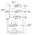
- a circuit for extracting control plane data from an incoming video signal is shown in Figure 2. This circuit receives the Y, U, and V components of the incoming video signal at an input means 1 and three comparators 2 determine whether any of the three components have the all 1's state denoting a control plane bit.
- a signal will be generated at a second output of the respective comparator 2.
- the three second outputs of the comparators are coupled to three inputs of a key generation circuit 6. This outputs a 3 bit control plane word in accordance with the outputs of the comparators and this is used to control the mixer.
- a further output of the key generation circuit 6 is coupled to enable input of an interpolation circuit 8 which also receives the incoming Y, U, and V words.
- an interpolation circuit 8 which also receives the incoming Y, U, and V words.
- the key generation circuit 6 enables the interpolation circuit 8 to identify which components need to be interpolated from neighbouring pixels and derives these in a well known manner using an arrangement of delays, adders, and multipliers.
- control plane value will be 000 and there will be no keying in of the input video signal into the background.
- control plane bits can be inserted into the video signal by simply using the three control plane bits to switch each of the Y, U, and V components between the source of video signals and an all 1's signal in accordance with the value of the respective control bit.
- a circuit for inserting the control plane bits into the video data is shown in Figure 5.
- Each of the Y, U, and V data words is connected to an input of a respective switch 20.
- Each switch is controlled by a control plane bit supplied by a source of control plane bits 22 to switch its output between the incoming component of the video signal and a source of an all 1's signal 24.
- the source 24 could typically be a shift register or a series of switches connected to logic 1.
- control plane bit controlling a switch When the control plane bit controlling a switch is a logic O then the respective component of the video signal will be switched through to the output. When the control plane bit is a logic 1 the all 1's signal will be switched through to the output of the switch 20. Thus each of the components of a video signal can be replaced by an all 1's state representing a control bit. The resultant output video signal can then be stored for future use if desired or supplied direct to a decoding circuit of the type shown in Figure 2.
- the U and V components are shared by adjacent pixels.
- the MSB of the control plane preferably replaces the Y component for a pixel. Since the U and V values for adjacent pixels are shared, the two LSB's of the control plane word are also shared.
- respective control plane bits are the same in adjacent pixels then there is no problem in this. For example if both the bits represented by the U component are O then the U component is left unchanged and when they are both 1 the U component is switched to the all 1's state. Where the bits are different, a random selection takes place and either a logical 0 or 1 is selected and the respective component switched to either the incoming video component or the all 1's state.
- Figure 3 shows a second embodiment of how a 24 bit YUV video signal and a 3 bit control plane signal for a pixel can be stored in a total of 24 bits of memory. This is done by using only 7 bits for each of the Y,U and V values and using the 3 spare bits thus created for the storage of the control plane.
- the luminance word is considered and if the least significance bit (which represents the darkest level of luminance) is used the second less significance bit is incremented.
- the most significant bit of the control plane is then inserted into the spare bit created by the rounding up operation. This could similarly be achieved by rounding down or simply discarding the LSB.
- This circuit would include inputs for the video signal and the control plane and circuitry to discard the appropriate LSB's and replace them with control plane bits. An output to a frame buffer would enable the resultant signal to be stored.
- the loss of the LSB in each of the Y,U and V components does not lead to any perceptable degregation of the image in normal viewing circumstances. It also enables existing video data storage units e.g. frame stores to be used for the storage of the data without the need for a separate store for the control plane.
- existing video data storage units e.g. frame stores to be used for the storage of the data without the need for a separate store for the control plane.
- the standard transmission format specified in CCIR recommendation 601 for YUV video data is the 4:2:2 structure. This involves transmitting alternate luminence and chrominance values. The order is shown in Figure 4. In this it will be seen that the order of transmission is; Y1, U1, Y2, V2, Y3, U3 .........
- pixels 1 and 2 When this transmission sequence is received adjacent pixels have to share the chrominance (U and V) values. For example, in a line of video data pixels 1 and 2 would share the same U value which would be derived from an average between the original U values for those two pixels, pixels 2 and 3 would share the same V values which would be similarly derived, pixels 3 and 4 would share the same U values etc.
- a three bit control plane could be incorporated in such a signal either after the averaging process, or before the averaging process. In the latter case the averaging would then only take place on seven bits of data.
- control bits are designated C1,1 etc where the first numeral represents the pixel and the second numeral the bit, one representing the RSB and three the LSB. It can thus be seen that the U and V bits used for each pixel will also contain the respective control plane bits.
- a video signal received in the sequence of Figure 4 is reconstructed into YUV components and control plane for each pixel and if required can be converted to 8 bit words for each component by randomly assigning a bit to the LSB.
- the signal can then be keyed into a second video signal preferably also of 8 bit format using the control plane value stored in the three control bits to control the proportions in which the two signals are combined.
- the invention will also operate with control planes which have more than three data bits. In such situations at least one data bit of each data word will comprise control plane data.
- Any video signal embodying the invention can be separated into video data and control plane data either in software or in dedicated hardware.
- the hardware solution would require means to receive the video signal and means to separate the control plane data from it before supplying the video data to a video mixer to be combined with a second video signal under the control of the control plane data.
- Such a system is described above with reference to Figure 2.
- the composition system can be based on that described in GB 2113950 which is mentioned above.
Landscapes
- Engineering & Computer Science (AREA)
- Multimedia (AREA)
- Signal Processing (AREA)
- Color Television Systems (AREA)
Claims (11)
- Verfahren zum Kombinieren eines digitalen Videosignals mit einem Kontrollebenensignal, wobei das Verfahren die Schritte Empfang eines digitalen Videosignals und ebenso Empfang eines entsprechenden Kontrollebenensignals beinhaltet, dadurch gekennzeichnet, daß das Videosignal drei Datenworte für jedes Pixel beinhaltet und das Kontrollebenensignal drei Datenbits für jedes Pixel beinhaltet, und durch die Verfahrensschritte Zuordnung jedes der drei Datenworte zu einem entsprechenden Kontrollebenen-Datenbit und Ersetzen eines Datenworts in dem Videosignal durch eine vorherbestimmte Kombination von Bits, wenn sein entsprechendes Kontrollebenen-Datenbit einen ersten logischen Signalpegel hat und Unverändertlassen des Datenwortes wenn sein entsprechendes Kontrollebenen-Datenbit einen zweiten logischen Signalpegel hat.
- System zum Kombinieren eines digitalen Videosignals mit einem Kontrollebenensignal umfassend eine Vorrichtung zum Empfang eines digitalen Videosignals und eine Vorrichtung (22) zum Empfang eines Kontrollebenensignals, dadurch gekennzeichnet, daß das Videosignal drei Datenworte für jedes Pixel beinhaltet und das Kontrollebenen-Signal drei Datenworte für jedes Pixel beinhaltet und durch eine Vorrichtung zum Zuordnen jedes der drei Datenworte zu einem entsprechenden Kontrollebenen-Datenbit, und eine Vorrichtung (20) zum Ersetzen eines Datenwortes in dem Videosignal durch eine vorherbestimmte Kombination von Bits, wenn sein entsprechendes Kontrollebenen-Datenbit einen ersten logischen Signalpegel hat und Unverändertlassen des Datenwortes, wenn sein entsprechendes Kontrollebenen-Datenbit einen zweiten logischen Signalpegel hat.
- System für digitale Videobildzusammensetzung umfassend eine Vorrichtung (1) zum Empfang eines ersten digitalen Videosignals mit einer Vielzahl von Datenworten für jedes Pixel, eine Vorrichtung zum Empfang eines zweiten digitalen Videosignals, und eine Vorrichtung zum Kombinieren des ersten und des zweiten digitalen Videosignals für jedes Pixel in variablen Proportionen abhängig von dem Wert von mindestens einem dem Pixel entsprechenden Kontrollebenen-Datenbit, dadurch gekennzeichnet, daß mindestens eine Kombination von Bits in einem Datenwort für ein Pixel in dem ersten Videosignal das Vorhandensein eines Kontrollebenen-Datenbits anzeigt, weiter gekennzeichnet durch eine Vorrichtung (6) zum Erzeugen eines Kontrollebenen-Datenbits für dieses Pixel in Erwiderung auf die Kombination von Bits in dem Datenwort, und durch eine Vorrichtung (8) zum Interpolieren eines Austausch-Videodatenwortes für dieses Pixel aus entsprechenden Datenworten in benachbarten Pixels zur Verwendung in der Vorrichtung zum Kombinieren.
- System nach Anspruch 3, in welchem das erste Videosignal drei Datenworte pro Pixel beinhaltet, von denen jedes mindestens eine Kombination von Bits hat, die das Vorhandensein eines Kontrollebenen-Datenbits anzeigt.
- Verfahren zum Kombinieren eines digitalen Videosignals mit einem Kontrollebenensignal, wobei das Verfahren die Schritte Emfang eines digitalen Videosignals und ebenso Empfang eines entsprechenden Kontrollebenensignals beinhaltet, dadurch gekennzeichnet, daß das Videosignal drei Datenworte für jedes Pixel hat, und das Kontrollebenen-Signal mindestens drei Datenbits für jedes Pixel hat und zumindest das am wenigsten bedeutende Bit jedes Datenwortes verworfen wird und jedes verworfene Bit durch ein entsprechendes der Kontrollebenen-Bits für dieses Pixel ersetzt wird.
- Verfahren nach Anspruch 5, dadurch gekennzeichnet, daß das Videosignal ein YUV-Signal im 4:2:2-Format beinhaltet.
- System zum Kombinieren eines digitalen Videosignals mit einem Kontrollebenensignal, umfassend eine Vorrichtung zum Empfang eines digitalen Videosignals und eine Vorrichtung zum Empfang eines Kontrollebenensignals, dadurch gekennzeichnet, daß das Videosignal drei Datenworte für jedes Pixel hat und das Kontrollebenen-Signal mindestens drei Datenbits für jedes Pixel hat, und weiter gekennzeichnet durch eine Vorrichtung zum Verwerfen oder Streichen mindestens des am wenigsten bedeutenden Bits von jedem Datenwort für ein Pixel und zu seinem Ersatz durch ein entsprechendes der Kontrollebenen-Bits für dieses Pixel.
- System nach Anspruch 7, dadurch gekennzeichnet, daß das Videosignal ein YUV-Signal im 4:2:2-Format beinhaltet.
- Digitales Videobild-Zusammensetzungssystem umfassend eine Vorrichtung zum Empfang eines ersten digitalen Videosignals, eine Vorrichtung zum Empfang eines zweiten digitalen Videosignals, eine Vorrichtung zum Kombinieren des ersten und des zweiten Videosignals für jedes Pixel in variablen Proportionen abhängig von dem Wert eines dem Pixel entsprechenden Kontrollebenensignals, dadurch gekennzeichnet, daß das erste Videosignal drei Datenworte pro Pixel beinhaltet und mindestens eines der Datenbits von jedem Datenwort Kontrollebenen-Daten aufweist, und weiter gekennzeichnet durch eine Vorrichtung zum Trennen der Kontrollebenen-Datenbits für jedes Pixel von dem ersten Videosignal.
- System nach Anspruch 9, dadurch gekennzeichnet, daß das am wenigsten bedeutende Bit jedes Datenwortes in dem ersten Videosignal ein Kontrollebenen-Datenbit aufweist.
- System nach Anspruch 9, dadurch gekennzeichnet, daß das erste Videosignal ein im 4:2:2-Format empfangenes YUV-Signal aufweist.
Applications Claiming Priority (3)
| Application Number | Priority Date | Filing Date | Title |
|---|---|---|---|
| GB898926377A GB8926377D0 (en) | 1989-11-22 | 1989-11-22 | Digital image composition systems |
| GB8926377 | 1989-11-22 | ||
| PCT/GB1990/001741 WO1991007845A1 (en) | 1989-11-22 | 1990-11-13 | Storage of digital image composition control signal |
Publications (2)
| Publication Number | Publication Date |
|---|---|
| EP0501988A1 EP0501988A1 (de) | 1992-09-09 |
| EP0501988B1 true EP0501988B1 (de) | 1996-03-06 |
Family
ID=10666714
Family Applications (1)
| Application Number | Title | Priority Date | Filing Date |
|---|---|---|---|
| EP90916506A Expired - Lifetime EP0501988B1 (de) | 1989-11-22 | 1990-11-13 | Speicherung des kontrollsignals für digitale bildzusammensetzung |
Country Status (3)
| Country | Link |
|---|---|
| EP (1) | EP0501988B1 (de) |
| GB (1) | GB8926377D0 (de) |
| WO (1) | WO1991007845A1 (de) |
Families Citing this family (5)
| Publication number | Priority date | Publication date | Assignee | Title |
|---|---|---|---|---|
| DE69330155T2 (de) * | 1992-11-05 | 2001-09-06 | Canon K.K., Tokio/Tokyo | Methode zur Durchführung von Bildeffekten im Empfänger eines übertragungssystems für kodierte Bewegtbinder |
| JP3705447B2 (ja) | 1994-11-17 | 2005-10-12 | 株式会社ルネサステクノロジ | 画像処理方法および画像処理装置 |
| EP0788282B1 (de) * | 1996-02-05 | 2010-01-20 | Panasonic Corporation | Quantisierungsverfahren |
| JPH10145583A (ja) * | 1996-11-14 | 1998-05-29 | Casio Comput Co Ltd | 画像処理装置 |
| AU2001290941A1 (en) * | 2000-09-15 | 2002-03-26 | En Technology Corporation | Video signal with integral data transmission |
Family Cites Families (3)
| Publication number | Priority date | Publication date | Assignee | Title |
|---|---|---|---|---|
| JPS58157255A (ja) * | 1982-03-13 | 1983-09-19 | Dainippon Screen Mfg Co Ltd | 画像走査記録方法 |
| JPS60233985A (ja) * | 1984-05-07 | 1985-11-20 | Nec Corp | デジタル映像信号の特殊効果発生装置 |
| JPS63114472A (ja) * | 1986-10-31 | 1988-05-19 | Victor Co Of Japan Ltd | 画像処理装置 |
-
1989
- 1989-11-22 GB GB898926377A patent/GB8926377D0/en active Pending
-
1990
- 1990-11-13 EP EP90916506A patent/EP0501988B1/de not_active Expired - Lifetime
- 1990-11-13 WO PCT/GB1990/001741 patent/WO1991007845A1/en not_active Ceased
Also Published As
| Publication number | Publication date |
|---|---|
| GB8926377D0 (en) | 1990-01-10 |
| EP0501988A1 (de) | 1992-09-09 |
| WO1991007845A1 (en) | 1991-05-30 |
Similar Documents
| Publication | Publication Date | Title |
|---|---|---|
| US5363219A (en) | Image processing method and apparatus | |
| US4720745A (en) | Method and apparatus for enhancing video displays | |
| US5838296A (en) | Apparatus for changing the magnification of video graphics prior to display therefor on a TV screen | |
| EP0885528B1 (de) | Videobildmischung in einem heimkommunikationsterminal | |
| US4517597A (en) | Method and apparatus for encoding and decoding video | |
| US5185655A (en) | Method and apparatus for encoding full color video data signals and protocol for encoding same | |
| US5140412A (en) | Method for color encoding and pixelization for image reconstruction | |
| WO1991007845A1 (en) | Storage of digital image composition control signal | |
| EP1215921B1 (de) | Programm zur Kompression von Bilddaten | |
| US4870479A (en) | Video graphics memory storage reduction technique | |
| JPH04270564A (ja) | カラー情報を有するシリアル画像データ圧縮方式 | |
| JPH04326669A (ja) | 画像符号化装置及び画像符号化方法 | |
| US5367343A (en) | Motion enhanced compressed video system | |
| US5218430A (en) | Color video transmission | |
| US4611233A (en) | Digital non-addition mixing apparatus for video signals | |
| JP3455078B2 (ja) | 画像処理装置及び画像処理方法 | |
| EP0680223B1 (de) | Verfahren und Vorrichtung zur Farbraumumwandlung unter Verwendung von Farbwerttabellen | |
| JPH09507635A (ja) | ディジタル画像のコーディング | |
| JP2942282B2 (ja) | デジタル画像処理装置 | |
| JPS59128873A (ja) | カラ−フアクシミリの画信号変換方式 | |
| JP2605029B2 (ja) | 画像処理方法 | |
| JPH09311669A (ja) | 画像処理装置及びその画像処理方法 | |
| JPS61169086A (ja) | 中間調画像の符号化装置 | |
| JPH03161868A (ja) | 画像記憶装置 | |
| JPS62266989A (ja) | 高能率符号化装置 |
Legal Events
| Date | Code | Title | Description |
|---|---|---|---|
| PUAI | Public reference made under article 153(3) epc to a published international application that has entered the european phase |
Free format text: ORIGINAL CODE: 0009012 |
|
| 17P | Request for examination filed |
Effective date: 19920513 |
|
| AK | Designated contracting states |
Kind code of ref document: A1 Designated state(s): GB |
|
| 17Q | First examination report despatched |
Effective date: 19940422 |
|
| GRAA | (expected) grant |
Free format text: ORIGINAL CODE: 0009210 |
|
| AK | Designated contracting states |
Kind code of ref document: B1 Designated state(s): GB |
|
| PLBE | No opposition filed within time limit |
Free format text: ORIGINAL CODE: 0009261 |
|
| STAA | Information on the status of an ep patent application or granted ep patent |
Free format text: STATUS: NO OPPOSITION FILED WITHIN TIME LIMIT |
|
| REG | Reference to a national code |
Ref country code: GB Ref legal event code: 732E |
|
| 26N | No opposition filed | ||
| PGFP | Annual fee paid to national office [announced via postgrant information from national office to epo] |
Ref country code: GB Payment date: 20011227 Year of fee payment: 12 |
|
| REG | Reference to a national code |
Ref country code: GB Ref legal event code: IF02 |
|
| PG25 | Lapsed in a contracting state [announced via postgrant information from national office to epo] |
Ref country code: GB Free format text: LAPSE BECAUSE OF NON-PAYMENT OF DUE FEES Effective date: 20021113 |
|
| GBPC | Gb: european patent ceased through non-payment of renewal fee |