EP0502369A2 - Procédé et appareil de traitement d'images par la mise au point des conditions de traitement d'image basée sur des indications de finition - Google Patents
Procédé et appareil de traitement d'images par la mise au point des conditions de traitement d'image basée sur des indications de finition Download PDFInfo
- Publication number
- EP0502369A2 EP0502369A2 EP92102870A EP92102870A EP0502369A2 EP 0502369 A2 EP0502369 A2 EP 0502369A2 EP 92102870 A EP92102870 A EP 92102870A EP 92102870 A EP92102870 A EP 92102870A EP 0502369 A2 EP0502369 A2 EP 0502369A2
- Authority
- EP
- European Patent Office
- Prior art keywords
- image
- hue
- setting
- image data
- image processing
- Prior art date
- Legal status (The legal status is an assumption and is not a legal conclusion. Google has not performed a legal analysis and makes no representation as to the accuracy of the status listed.)
- Granted
Links
Images



Classifications
-
- H—ELECTRICITY
- H04—ELECTRIC COMMUNICATION TECHNIQUE
- H04N—PICTORIAL COMMUNICATION, e.g. TELEVISION
- H04N1/00—Scanning, transmission or reproduction of documents or the like, e.g. facsimile transmission; Details thereof
- H04N1/46—Colour picture communication systems
- H04N1/56—Processing of colour picture signals
- H04N1/60—Colour correction or control
- H04N1/62—Retouching, i.e. modification of isolated colours only or in isolated picture areas only
- H04N1/628—Memory colours, e.g. skin or sky
-
- H—ELECTRICITY
- H04—ELECTRIC COMMUNICATION TECHNIQUE
- H04N—PICTORIAL COMMUNICATION, e.g. TELEVISION
- H04N1/00—Scanning, transmission or reproduction of documents or the like, e.g. facsimile transmission; Details thereof
- H04N1/46—Colour picture communication systems
- H04N1/56—Processing of colour picture signals
- H04N1/60—Colour correction or control
-
- H—ELECTRICITY
- H04—ELECTRIC COMMUNICATION TECHNIQUE
- H04N—PICTORIAL COMMUNICATION, e.g. TELEVISION
- H04N1/00—Scanning, transmission or reproduction of documents or the like, e.g. facsimile transmission; Details thereof
- H04N1/46—Colour picture communication systems
- H04N1/56—Processing of colour picture signals
- H04N1/60—Colour correction or control
- H04N1/62—Retouching, i.e. modification of isolated colours only or in isolated picture areas only
- H04N1/622—Retouching, i.e. modification of isolated colours only or in isolated picture areas only with simulation on a subsidiary picture reproducer
Definitions
- the present invention relates to a method of and an apparatus for electrically processing each of images wherein an operator can automatically set up image processing conditions based on desired finishing information to form a reproduced image having the optimum hue.
- An image scanning reading and reproducing system is widely used in the printing and platemaking fields, for example, for electrically processing image information stored in originals or subjects to be read so as to produce original film plates with a view toward simplifying working processes and improving the quality of printed images.
- a so-called pre-scan operation for firstly feeding an original cassette to a reading unit and then setting up conditions (hereinafter called "image processing conditions") such as magnification, image processing, etc. is carried out. Then, a so-called main-scan operation for setting up the optimum image processing conditions based on image information obtained by the pre-scan operation and reading image information again in accordance with the image processing conditions is performed.
- the above disclosure has, however, a problem that when objects such as a wooden wall, a sand beach, etc. having colors similar to a skin color exist in an image or picture, they are also recognized as objects to be processed, so that appropriate image processing conditions cannot be set up.
- the present applicant has proposed a means in which particular spots or places at which image processing conditions are set up are designated or specified and the image processing conditions are set only to the particular spots, thereby making it possible to avoid such a problem (see Japanese Patent Application No. 2-229706).
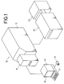
- reference numeral 10 indicates an image scanning reading and reproducing system.
- the image scanning reading and reproducing system 10 basically comprises an image reading apparatus 12, an original cassette feeding apparatus 16 capable of automatically feeding an original cassette 14 (see FIG. 2) with originals S to be read held therein to the image reading apparatus 12, a console 18 for manipulating the image reading apparatus 12, an image output apparatus 20 for reproducing, as an output, image information read by the image reading apparatus 12 on a photographic film, and an automatic photographic processor 22 for developing the film to produce an original film plate.
- the console 18 includes a CRT display 19 for displaying image information or the like thereon, a keyboard 21 and a mouse 23.
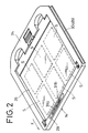
- the original cassette 14 shown in FIG. 2 is used to hold six light-transmissive originals S such as a 135-mm film between two support glass panels 26 enclosed by a frame 24 shaped substantially in the form of a square.
- the original cassette 14 has V-shaped grooves 30a, 30b which are defined in opposite sides thereof extending in an auxiliary scanning direction (i.e., in the direction indicated by the arrow X in FIG. 2) to feed the original cassette 14 toward the image reading apparatus 12 and which extend along the direction in which the original cassette 14 is fed.
- the cassette identifying unit 29 is made up by a combination of a plurality of light-transmissive portions 31a and light-intransmissive portions 31b.
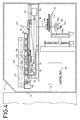
- FIG. 3 shows the structure of the original cassette feeding apparatus 16.
- the original cassette feeding apparatus 16 is surrounded by a casing 32 and comprises a cassette holding means 34 for accommodating the original cassette 14 therein, a cassette identifying means 36 for identifying the original cassette 14, and a cassette feeding means 38 for feeding the original cassette 14 stored in the cassette holding means 34 to the image reading apparatus 12 to which the original cassette feeding apparatus 16 is connected.
- the original cassette feeding apparatus 16 has a cassette insertion table 44 disposed in front of the original cassette feeding apparatus 16 and a cassette insertion hole 46 defined in the frontal part thereof.
- a pair of feed-in, i.e., insertion rollers 50 for inserting the original cassette 14 into the original cassette feeding apparatus 16 is disposed in an inner region corresponding to the cassette insertion hole 46.
- the cassette identifying means 36 is made up by a combination of a plurality of light-emitting devices and light-detecting devices. In addition, the cassette identifying means 36 reads data set in the cassette identifying unit 29 of the original cassette 14 delivered by a pair of feed rollers 37 so as to identify the original cassette 14 and the type of the original S or the like.
- the cassette holding means 34 comprises a cage which is supported by four guide bars 52a through 52d provided upright within the casing 32.
- the cassette holding means 34 can be moved in upward and downward directions (i.e., in the direction indicated by the arrow Z) by a worm gear 56 coupled to an electric motor 54 and a chain 58.
- the image reading apparatus 12 surrounded by a casing 92 has a cassette insertion hole 94 defined therein, which communicates with the original cassette feeding apparatus 16.
- the image reading apparatus 12 there is disposed near the cassette insertion hole 94, an identifying mechanism 98 for identifying the original cassette 14 and the type of each of the originals S stored in the original cassette 14.
- the identifying mechanism 98 is constructed in a manner similar to the cassette identifying means 36 disposed in the original cassette feeding apparatus 16.
- a feed mechanism 100 is disposed near the identifying mechanism 98, whereas the other end thereof extends to a position above a turntable 132 to be described later.
- the feed mechanism 100 has a plurality of guide rollers 106, which are held in point-to-point contact with the V-shaped grooves 30a, 30b of the original cassette 14.
- the feed mechanism 100 also has a plurality of feed rollers 108 which are brought into contact with a feed surface of the frame 24 of the original cassette 14 and which feed the original cassette 14 in a desired direction.
- Below the feed mechanism 100 there is disposed an original table 110 which is movable in an auxiliary scanning direction (i.e., in the direction indicated by the arrow X) by an auxiliary scanning mechanism 112.
- the auxiliary scanning mechanism 112 includes a rotative drive source 114 to which there is coupled a ball screw 116 that moves the original table 110 in the direction indicated by the arrow X.
- the original table 110 has a trimming mechanism 120 for moving the original cassette 14 back and forth in a trimming direction, i.e., in a direction normal to the auxiliary scanning direction (i.e., the direction indicated by the arrow X).
- the trimming mechanism 120 has a rotative drive source 122 mounted on the original table 110, which in turn rotates a ball screw 124 so as to move a trimming table 126 in the direction normal to the auxiliary scanning direction.
- the trimming table 126 has an aperture 128 which extends therethrough.
- a turntable 132 is mounted in the aperture 128 and supports thereon an unillustrated mechanism for rotating the original cassette 14 by a predetermined angle.
- a light source 140 which constitutes a transmissive illuminating mechanism.
- an image reading unit 150 serving as an image reading means for photoelectrically reading illuminating light L emitted from the light source 140 is disposed below the light source 140.
- the image reading unit 150 has a focusing lens 152 and a photoelectrically converting unit 156 comprising a plurality of CCDs 154a through 154c.
- the image reading unit 150 photoelectrically reads image information carried by each of the originals S as image information corresponding to the colors of R, G, and B.
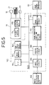
- the image reading apparatus 12 constructed as described above is driven under control by a control unit 160.
- the control unit 160 includes an image memory 162, a hue space data memory 163, a CPU 164, an input control circuit 166, a preprocessing circuit 168, an image processing condition setting circuit 170 and an image processing circuit 172.
- the control unit 160 and the console 18 constitutes an image processing apparatus according to the present embodiment, which serves as a determining/displaying means and/or an image data extracting means.
- the CPU 164 performs general control of the image reading apparatus 12.
- the console 18 comprises a video buffer 174 and a display control unit 176.
- the console 18 generates an output to be sent to the CRT display 19 thereof, and accepts inputs from the keyboard 21 and the mouse 23 electrically connected to the console 18.
- the CRT display 19 serves as an image displaying means
- the keyboard 21 and the mouse 23 serves as an instructing or specifying means and a finishing information setting means respectively.
- the input control circuit 166 determines the type of the original cassette 14 and the like, and controls the region of an image to be read by the photoelectrically converting unit 156. In addition, the input control circuit 166 controls an image reading operation of the photoelectrically converting unit 156.
- the preprocessing circuit 168 pre-processes image data obtained from the photoelectrically converting unit 156 and sends thus pre-processed image data to the console 18 and the image processing condition setting circuit 170.
- the image memory 162 stores the read image data therein.
- the image processing condition setting circuit 170 sets up image processing conditions at the time of the main-scan process on the basis of image data obtained by scanning the original S to be read.
- the image processing circuit 172 electrically processes the image data fed from the image processing condition setting circuit 170 in accordance with the image processing conditions so as to output the same to the image output apparatus 20.
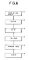
- the original cassette 14 with a desired original S stored therein is inserted from the cassette insertion hole 46 of the original cassette feeding apparatus 16 shown in FIG. 3 (Step S1).
- the original cassette feeding apparatus 16 is activated to rotate the insertion rollers 50 and the feed rollers 37 so as to delivery the original cassette 14 to the cassette identifying means 36 through the cassette holding means 34.
- the original cassette 14 is returned to a predetermined position in the cassette holding means 34. Then, the motor 54 is energized to cause the worm gear 56 and the chain 58 to move the cassette holding means 34 in the direction indicated by the arrow Z. Thereafter, the cassette feeding apparatus 38 is actuated to feed the original cassette 14 to the image reading apparatus 12 through the cassette insertion hole 94.
- the identifying mechanism 98 of the image reading apparatus 12 is actuated to identify the original cassette 14. Then, the feed rollers 108 are rotated to feed the original cassette 14 to a position above the turntable 132 in a state in which the original cassette 14 has been held by the guide rollers 106 held in point-to-point contact with the V-shaped grooves 30a, 30b.
- the auxiliary scanning mechanism 112 is actuated to feed the original cassette 14 together with the original table 110 in the direction indicated by the arrow X, i.e., in the auxiliary scanning direction, thereby causing the image reading unit 150 to read, i.e., pre-scan image information for setting up processing-conditions (Step S2).
- the illuminating light L emitted from the light source 140 passes through one of the originals S to be read, which are stored in the original cassette 14, followed by travelling to the CCDs 154a through 154c of the photoelectrically converting unit 156 through the focusing lens 152.
- the CCDs 154a through 154c convert the illuminating light L which has passed through the original S into an electric signal.
- the electric signal is subjected to a predetermined process in the preprocessing circuit 168 of the control unit 160, and the electric signal thus processed is stored in the image memory 162 as image data and displayed on the CRT display 19 of the console 18.
- the image processing condition setting circuit 170 sets up image processing conditions based on the finishing information or the like (Step S3).
- the image processing conditions includes conditions for setting up, for example, the degrees of highlights and shadows, dot percent, gradation, color correction, sharpness, undercolor removal, etc. with respect to the original film plate.
- the main-scan image data is then sent to the image output apparatus 20, where it is converted into a light signal such as a laser beam. Thereafter, the light signal thus converted is reproduced on a photographic film as an image (Step S5).
- the photographic film is sent to the automatic photographic processor 22, where it is developed thereby to obtain a desired original film plate (Step S6).
- Step S3 The setting-up of the image processing conditions in the set-up process (Step S3) will now be described below in detail based on flowcharts shown in FIGS. 7 and 8.
- a first method of setting up the image processing conditions will first be described in accordance with FIG. 7.
- An image obtained by the pre-scan process in Step S2 is displayed as a pre-scan image on the CRT display 19 together with a menu indicative of desired finishing information as shown in FIG. 9.
- the finishing information represents information for setting the pre-scan image to desired brightness and finishing, i.e., bringing the same to completion as a final image.
- Step S10 the operator makes use of the mouse 23 to select desired finishing information.
- desired finishing information A description will be made in a case in which a brightness message indicative of "as carried by original” and a finishing message indicative of "further improve her complexion", for example, are selected as finishing information.
- the operator specifies spots (or a spot) at which the operator wants to further improve her complexion on the pre-scan image as a plurality of particular spots or places (or a single place) by means of clicks produced by the mouse 23, for example (Step S12). If the particular places are not specified by the operator (Step S11), then main subjects are automatically extracted based on a second method of setting up image processing conditions, which will be described later (Step S13).
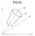
- the CPU 164 determines (in Step S14) whether or not image data at particular places specified by the mouse 23 are data which exist in a skin-color hue space. More specifically, hue space data set up in advance according to various finishing information statistically determined have been stored in the hue space data memory 163. Thus, a desired skin-color hue space data is selected from the hue space data stored in the hue space data memory 163. As illustrated in FIG. 10 by way of example, the skin-color hue space data is set within a cone-shaped space 181 defined about a standard skin-color axis 179 in a YMC three-dimensional hue space in such a manner as to be directed from an image low-density region to an image high-density region.
- the setting of the skin-color hue space data within the cone-shaped space 181 defined thereabout can meet various skin colors having different brightness. Since the cone-shaped space 181 can also be represented in simple linear form, the time required to perform arithmetic operations on the image data upon the determination in Step S14, can be reduced.
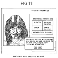
- the CPU 164 When the image data at the particular places are not included in the region set up by the skin-color hue space data, the CPU 164 now displays a message indicative of "specified spots (particular places) do not represent the skin color, but are you going to use the same as skin-color finishing information ?" on the pre-scan image of FIG. 9 displayed on the CRT display 19, as shown in FIG. 11. At this time, the operator selects "Cancel, i.e., No" if the operator wants to specify the particular places again (Step S15), and repeats the routine procedure from Step S12. If the image data at the particular places are used for the correction of the image processing conditions as they are, then the operator selects "Yes". When the image data at the particular places exist in the region set up by the skin-color hue space data, the character representation shown in FIG. 11 is not performed.
- the image processing condition setting circuit 170 sets up image processing conditions based on the correction values h y , h m , h c (Step S18).
- the image processing conditions have been set up in this way, e.g., when the image data at the particular places do not represent the skin color, the message shown in FIG. 11 is displayed on the CRT display 19. Therefore, even if the particular places are regarded as small or unwanted errors occur in setting up of the image processing conditions, the operator can recognize such undesired state beforehand. Thus, the operator can accurately set up image processing conditions at all times by specifying the particular places again in accordance with the message. In addition, the operator can select the particular places as requested, thereby causing no problem that colors indicative of, for example, a wall, a sandy beach, etc., which are analogous or similar to the skin color, are processed as the skin color.
- Step S11 When particular places are not specified (Step S11) after the message indicative of "further improve her complexion", for example, has been selected as the finishing information in Step S10, the CPU 164 automatically extracts desired main subjects from the pre-scan image (Step S13).
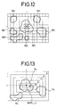
- the CPU 164 extracts pixel data in the region set up by the skin-color hue space data shown in FIG. 10 from the pre-scan image data stored in the image memory 162 (Step S20). Then, regions at which the pixel data are continuously distributed, are extracted as skin-color regions 180 as illustrated in FIG. 12. Further, three large skin-color regions 180 are successively selected from the skin-color regions 180 referred to above (Step S13) so as to be determined as main subjects R1, R2, R3 (Step S21). When the main subjects R1, R2, R3 are selected, the skin-color regions 180 are set on condition that 8 pixels about (i, j)th image data are regarded as being the same region as shown in FIG. 12, thereby determining the main subjects R1, R2, R3. Thus, the skin-color region 180 defined in the form of one pixel level is no longer set up.
- weights W1, W2, W3 of the main subjects R1, R2, R3 are respectively calculated based on the following equations using respective weights WM (i, j) (WM(i, j) represents the weight with respect to a (i, j)th pixel) in a weight map set as shown in FIG. 13 (Step S22).
- the central weight in the weight map is greater than the peripheral weights because one of the main subjects is normally located in the center of the weight map.
- W1 ⁇ R1 WM (i, j)
- W2 ⁇ R2 WM (i, j)
- W3 ⁇ R3 WM (i, j)
- ⁇ R1 , ⁇ R2 , ⁇ R3 respectively represent operation symbols indicative of addition of the weights WM (i, j) with respect to the main subjects R1, R2, R3.
- the weight ratios (WR1, WR2, WR3) are determined from the weights W1, W2, W3 calculated in the above-described manner (Step S23).
- Steps S17 and S18 of the first image processing conditions setting method the YMC average-value ratios referred to above are then used to calculate correction values and set up the image processing conditions based on the correction values thus calculated.
- particular places recognized as optimum are automatically set up to enable the setting up of the image processing conditions. At this time, the operator is released from setting up the particular places, thereby making it possible to improve the efficiency of the work.
- the operator can freely make a judgment as to whether or not the particular places should be specified.
- a reproduced image obtained in accordance with image processing conditions automatically set up based on finishing information is deteriorated, particular places are specified to correct the image, thereby enabling the formation of a desired reproduced image.
- the degree of freedom of the operator can greatly be improved.
Landscapes
- Engineering & Computer Science (AREA)
- Multimedia (AREA)
- Signal Processing (AREA)
- Facsimile Image Signal Circuits (AREA)
- Processing Or Creating Images (AREA)
- Image Processing (AREA)
- Color Image Communication Systems (AREA)
- Editing Of Facsimile Originals (AREA)
Applications Claiming Priority (2)
| Application Number | Priority Date | Filing Date | Title |
|---|---|---|---|
| JP27586/91 | 1991-02-21 | ||
| JP3027586A JP2878855B2 (ja) | 1991-02-21 | 1991-02-21 | 画像処理装置 |
Publications (3)
| Publication Number | Publication Date |
|---|---|
| EP0502369A2 true EP0502369A2 (fr) | 1992-09-09 |
| EP0502369A3 EP0502369A3 (en) | 1993-04-07 |
| EP0502369B1 EP0502369B1 (fr) | 1997-01-29 |
Family
ID=12225060
Family Applications (1)
| Application Number | Title | Priority Date | Filing Date |
|---|---|---|---|
| EP92102870A Expired - Lifetime EP0502369B1 (fr) | 1991-02-21 | 1992-02-20 | Procédé et appareil de traitement d'images par la mise au point des conditions de traitement d'image basée sur des indications de finition |
Country Status (4)
| Country | Link |
|---|---|
| US (1) | US5276511A (fr) |
| EP (1) | EP0502369B1 (fr) |
| JP (1) | JP2878855B2 (fr) |
| DE (1) | DE69217095T2 (fr) |
Cited By (5)
| Publication number | Priority date | Publication date | Assignee | Title |
|---|---|---|---|---|
| WO1996008915A1 (fr) * | 1994-09-16 | 1996-03-21 | Linotype-Hell Ag | Environnements de teinte, saturation et luminance (hsl) dans un espace des couleurs cmj |
| EP0757473A3 (fr) * | 1995-08-01 | 1997-12-10 | Canon Kabushiki Kaisha | Appareil et procédé de traitement d'images |
| EP1089552A3 (fr) * | 1999-09-30 | 2003-03-19 | Seiko Epson Corporation | Appareil et procédé de correction de couleurs |
| EP1482724A1 (fr) * | 2003-05-19 | 2004-12-01 | STMicroelectronics S.A. | Méthode de traitement d'images numériques avec correction d'exposition par reconnaissance de zones appartenant à la peau du sujet photographié |
| CN101138806B (zh) * | 2007-10-19 | 2010-06-02 | 江苏科技大学 | 超声频脉冲等离子弧切割方法及装置 |
Families Citing this family (17)
| Publication number | Priority date | Publication date | Assignee | Title |
|---|---|---|---|---|
| JP3062338B2 (ja) * | 1991-03-01 | 2000-07-10 | キヤノン株式会社 | 画像処理装置 |
| JPH06311353A (ja) * | 1993-04-19 | 1994-11-04 | Brother Ind Ltd | カラー画像形成装置 |
| US5477353A (en) * | 1993-04-21 | 1995-12-19 | Olympus Optical Co., Ltd. | Photographic image processing system having laboratory unit for processing film and photographer unit for supplying printing information |
| US5574573A (en) * | 1993-10-29 | 1996-11-12 | Eastman Kodak Company | Compression method for a standardized image library |
| JP3491998B2 (ja) * | 1994-01-31 | 2004-02-03 | キヤノン株式会社 | 画像処理方法及び装置 |
| US5521723A (en) * | 1994-06-16 | 1996-05-28 | Eastman Kodak Company | System for producing a color hardcopy having the color and the tone reproduction characteristics of a photograph |
| US5652663A (en) * | 1994-07-29 | 1997-07-29 | Polaroid Corporation | Preview buffer for electronic scanner |
| DE69827703T2 (de) | 1997-06-17 | 2005-05-25 | Seiko Epson Corp. | Verfahren und Vorrichtung zum Einstellen der Farbe |
| JPH11187199A (ja) * | 1997-12-17 | 1999-07-09 | Fuji Photo Film Co Ltd | 画像入力装置 |
| US6618170B1 (en) * | 1999-05-14 | 2003-09-09 | Xerox Corporation | User interface comprising hue shift control for color printing |
| JP4368513B2 (ja) | 1999-12-27 | 2009-11-18 | 富士フイルム株式会社 | 画像処理方法および装置並びに記録媒体 |
| JP4421761B2 (ja) | 1999-12-27 | 2010-02-24 | 富士フイルム株式会社 | 画像処理方法および装置並びに記録媒体 |
| US7106887B2 (en) * | 2000-04-13 | 2006-09-12 | Fuji Photo Film Co., Ltd. | Image processing method using conditions corresponding to an identified person |
| US20030190090A1 (en) * | 2002-04-09 | 2003-10-09 | Beeman Edward S. | System and method for digital-image enhancement |
| US7394486B2 (en) | 2002-09-26 | 2008-07-01 | Seiko Epson Corporation | Adjusting output image of image data |
| JP2010015607A (ja) * | 2003-11-05 | 2010-01-21 | Seiko Epson Corp | 画像処理装置、画像処理方法 |
| JP2006325015A (ja) * | 2005-05-19 | 2006-11-30 | Konica Minolta Photo Imaging Inc | 画像処理方法、画像処理装置、撮像装置及び画像処理プログラム |
Citations (3)
| Publication number | Priority date | Publication date | Assignee | Title |
|---|---|---|---|---|
| GB2117902A (en) | 1982-04-06 | 1983-10-19 | Loge Interpretation Syst | Colour detection and-or modification |
| US4476487A (en) | 1982-05-04 | 1984-10-09 | Dr. -Ing. Rudolf Hell Gmbh | Method and circuit arrangement for partial electronic retouch in color image reproduction |
| EP0354490A2 (fr) | 1988-08-11 | 1990-02-14 | Dainippon Screen Mfg. Co., Ltd. | Procédé et appareil pour ajuster des règles de séparation de couleur |
Family Cites Families (10)
| Publication number | Priority date | Publication date | Assignee | Title |
|---|---|---|---|---|
| JPH0748795B2 (ja) * | 1982-07-09 | 1995-05-24 | 富士写真フイルム株式会社 | 画像入出力装置 |
| JPS6091770A (ja) * | 1983-10-26 | 1985-05-23 | Canon Inc | カラ−画像処理装置 |
| US4689669A (en) * | 1984-11-27 | 1987-08-25 | Sony Corporation | Color graphics data processing apparatus |
| JPS62111570A (ja) * | 1985-11-09 | 1987-05-22 | Fuji Photo Film Co Ltd | 画像入出力システムにおける出力信号処理条件の自動設定方法 |
| JP2651482B2 (ja) * | 1987-12-29 | 1997-09-10 | 大日本スクリーン製造 株式会社 | 画像処理装置における表示装置 |
| EP0639027A1 (fr) * | 1988-01-08 | 1995-02-15 | Fuji Photo Film Co., Ltd. | Procédé et appareil pour l'analyse de films en couleurs |
| US5194946A (en) * | 1988-10-13 | 1993-03-16 | Fuji Photo Film Co., Ltd. | Color scanner and automatic setting method of signal processing conditions |
| US5119182A (en) * | 1989-02-23 | 1992-06-02 | Minolta Camera Kabushiki Kaisha | Image forming apparatus comprising sample image printing mode and image forming method therefor |
| US5155588A (en) * | 1990-02-06 | 1992-10-13 | Levien Raphael L | Color correction and apparatus for photographic reproduction |
| US5121198A (en) * | 1990-06-28 | 1992-06-09 | Eastman Kodak Company | Method of setting the contrast of a color video picture in a computer controlled photographic film analyzing system |
-
1991
- 1991-02-21 JP JP3027586A patent/JP2878855B2/ja not_active Expired - Fee Related
-
1992
- 1992-02-19 US US07/836,837 patent/US5276511A/en not_active Expired - Lifetime
- 1992-02-20 DE DE69217095T patent/DE69217095T2/de not_active Expired - Lifetime
- 1992-02-20 EP EP92102870A patent/EP0502369B1/fr not_active Expired - Lifetime
Patent Citations (4)
| Publication number | Priority date | Publication date | Assignee | Title |
|---|---|---|---|---|
| GB2117902A (en) | 1982-04-06 | 1983-10-19 | Loge Interpretation Syst | Colour detection and-or modification |
| US4476487A (en) | 1982-05-04 | 1984-10-09 | Dr. -Ing. Rudolf Hell Gmbh | Method and circuit arrangement for partial electronic retouch in color image reproduction |
| EP0354490A2 (fr) | 1988-08-11 | 1990-02-14 | Dainippon Screen Mfg. Co., Ltd. | Procédé et appareil pour ajuster des règles de séparation de couleur |
| JPH0250859A (ja) | 1988-08-11 | 1990-02-20 | Dainippon Screen Mfg Co Ltd | 色分解条件設定方法および装置 |
Cited By (8)
| Publication number | Priority date | Publication date | Assignee | Title |
|---|---|---|---|---|
| WO1996008915A1 (fr) * | 1994-09-16 | 1996-03-21 | Linotype-Hell Ag | Environnements de teinte, saturation et luminance (hsl) dans un espace des couleurs cmj |
| EP0757473A3 (fr) * | 1995-08-01 | 1997-12-10 | Canon Kabushiki Kaisha | Appareil et procédé de traitement d'images |
| US6160579A (en) * | 1995-08-01 | 2000-12-12 | Canon Kabushiki Kaisha | Image processing apparatus and method |
| US7098944B1 (en) | 1995-08-01 | 2006-08-29 | Canon Kabushiki Kaisha | Image processing apparatus and method |
| EP1089552A3 (fr) * | 1999-09-30 | 2003-03-19 | Seiko Epson Corporation | Appareil et procédé de correction de couleurs |
| US6947078B1 (en) | 1999-09-30 | 2005-09-20 | Seiko Epson Corporation | Color correction apparatus, color correction method, and recording medium having color correction control program recorded |
| EP1482724A1 (fr) * | 2003-05-19 | 2004-12-01 | STMicroelectronics S.A. | Méthode de traitement d'images numériques avec correction d'exposition par reconnaissance de zones appartenant à la peau du sujet photographié |
| CN101138806B (zh) * | 2007-10-19 | 2010-06-02 | 江苏科技大学 | 超声频脉冲等离子弧切割方法及装置 |
Also Published As
| Publication number | Publication date |
|---|---|
| EP0502369B1 (fr) | 1997-01-29 |
| JPH04266264A (ja) | 1992-09-22 |
| DE69217095T2 (de) | 1997-05-15 |
| JP2878855B2 (ja) | 1999-04-05 |
| DE69217095D1 (de) | 1997-03-13 |
| EP0502369A3 (en) | 1993-04-07 |
| US5276511A (en) | 1994-01-04 |
Similar Documents
| Publication | Publication Date | Title |
|---|---|---|
| US5276511A (en) | Method of and apparatus for processing image by setting up image processing conditions on the basis of finishing information | |
| US5202934A (en) | Method of and apparatus for reading image | |
| EP1206118B1 (fr) | Appareil de traitement d'image, procédé de traitement d'image et support d'enregistrement | |
| EP0936804A2 (fr) | Procédé et appareil de traitement d'images | |
| EP0500112B1 (fr) | Appareil et procédé de lecture d'images pour la détermination automatique de la zone d'image dans une zone de lecture plus large | |
| JPH0514700A (ja) | 画像処理方法および装置並びにこの装置に使用される較正用チヤート | |
| EP0363988A2 (fr) | Balayeur en couleur et procédé automatique de calage | |
| US6940546B2 (en) | Method for compensating a digital image for light falloff while minimizing light balance change | |
| US7013052B1 (en) | Image processing apparatus | |
| US6295388B1 (en) | Method for selecting an area of full resolution image detail for viewing during scanning | |
| JP2889860B2 (ja) | 色分解走査装置の作動における画像の嵌込みを行う方法 | |
| EP0573069B1 (fr) | Procédé et appareil pour calibrer un dispositif de balayage couleur | |
| US6057941A (en) | Microfilm reader and control method therefor | |
| WO1996031838A1 (fr) | Imprimante et procede d'alignement du sujet principal pour impression en 3d faisant intervenir un ecran de controle video pour l'exposition | |
| US6958825B2 (en) | Print system | |
| US5130824A (en) | System for and method of reading image information | |
| US6430376B1 (en) | Image processing apparatus, image output device, and image processing system | |
| CN1271111A (zh) | 数字曝光式照片处理装置 | |
| US5909537A (en) | Control method for microfilm image reader | |
| JP2604059B2 (ja) | 画像読取装置 | |
| WO1991002286A1 (fr) | Reproduction photographique | |
| JPH06237373A (ja) | カラースキャナにおける色補正方法および装置 | |
| JP2000305193A (ja) | 写真プリント処理方法および装置 | |
| US6160911A (en) | Method and apparatus for trimming an image and reproducing a desired part of an image | |
| JPH04111575A (ja) | 画像処理装置 |
Legal Events
| Date | Code | Title | Description |
|---|---|---|---|
| PUAI | Public reference made under article 153(3) epc to a published international application that has entered the european phase |
Free format text: ORIGINAL CODE: 0009012 |
|
| 17P | Request for examination filed |
Effective date: 19920220 |
|
| AK | Designated contracting states |
Kind code of ref document: A2 Designated state(s): DE FR GB |
|
| PUAL | Search report despatched |
Free format text: ORIGINAL CODE: 0009013 |
|
| AK | Designated contracting states |
Kind code of ref document: A3 Designated state(s): DE FR GB |
|
| 17Q | First examination report despatched |
Effective date: 19950919 |
|
| GRAG | Despatch of communication of intention to grant |
Free format text: ORIGINAL CODE: EPIDOS AGRA |
|
| GRAH | Despatch of communication of intention to grant a patent |
Free format text: ORIGINAL CODE: EPIDOS IGRA |
|
| GRAH | Despatch of communication of intention to grant a patent |
Free format text: ORIGINAL CODE: EPIDOS IGRA |
|
| GRAA | (expected) grant |
Free format text: ORIGINAL CODE: 0009210 |
|
| AK | Designated contracting states |
Kind code of ref document: B1 Designated state(s): DE FR GB |
|
| REF | Corresponds to: |
Ref document number: 69217095 Country of ref document: DE Date of ref document: 19970313 |
|
| ET | Fr: translation filed | ||
| PLBE | No opposition filed within time limit |
Free format text: ORIGINAL CODE: 0009261 |
|
| 26N | No opposition filed | ||
| REG | Reference to a national code |
Ref country code: GB Ref legal event code: IF02 |
|
| REG | Reference to a national code |
Ref country code: GB Ref legal event code: 732E |
|
| REG | Reference to a national code |
Ref country code: FR Ref legal event code: CD Ref country code: FR Ref legal event code: TP |
|
| REG | Reference to a national code |
Ref country code: FR Ref legal event code: ST Effective date: 20091030 |
|
| PG25 | Lapsed in a contracting state [announced via postgrant information from national office to epo] |
Ref country code: FR Free format text: LAPSE BECAUSE OF NON-PAYMENT OF DUE FEES Effective date: 20090302 |
|
| REG | Reference to a national code |
Ref country code: FR Ref legal event code: D3 |
|
| PGRI | Patent reinstated in contracting state [announced from national office to epo] |
Ref country code: FR Effective date: 20101115 |
|
| PGFP | Annual fee paid to national office [announced via postgrant information from national office to epo] |
Ref country code: FR Payment date: 20110218 Year of fee payment: 20 Ref country code: DE Payment date: 20110126 Year of fee payment: 20 |
|
| PGFP | Annual fee paid to national office [announced via postgrant information from national office to epo] |
Ref country code: GB Payment date: 20110216 Year of fee payment: 20 |
|
| REG | Reference to a national code |
Ref country code: DE Ref legal event code: R071 Ref document number: 69217095 Country of ref document: DE |
|
| REG | Reference to a national code |
Ref country code: DE Ref legal event code: R071 Ref document number: 69217095 Country of ref document: DE |
|
| REG | Reference to a national code |
Ref country code: GB Ref legal event code: PE20 Expiry date: 20120219 |
|
| PG25 | Lapsed in a contracting state [announced via postgrant information from national office to epo] |
Ref country code: DE Free format text: LAPSE BECAUSE OF EXPIRATION OF PROTECTION Effective date: 20120221 |
|
| PG25 | Lapsed in a contracting state [announced via postgrant information from national office to epo] |
Ref country code: GB Free format text: LAPSE BECAUSE OF EXPIRATION OF PROTECTION Effective date: 20120219 |