EP0502459A2 - Mehrwellenantriebsvorrichtung und Fluiddrehvorrichtung - Google Patents
Mehrwellenantriebsvorrichtung und Fluiddrehvorrichtung Download PDFInfo
- Publication number
- EP0502459A2 EP0502459A2 EP92103558A EP92103558A EP0502459A2 EP 0502459 A2 EP0502459 A2 EP 0502459A2 EP 92103558 A EP92103558 A EP 92103558A EP 92103558 A EP92103558 A EP 92103558A EP 0502459 A2 EP0502459 A2 EP 0502459A2
- Authority
- EP
- European Patent Office
- Prior art keywords
- shafts
- rotational angle
- rotating
- rotors
- pulse signal
- Prior art date
- Legal status (The legal status is an assumption and is not a legal conclusion. Google has not performed a legal analysis and makes no representation as to the accuracy of the status listed.)
- Granted
Links
Images


Classifications
-
- H—ELECTRICITY
- H02—GENERATION; CONVERSION OR DISTRIBUTION OF ELECTRIC POWER
- H02P—CONTROL OR REGULATION OF ELECTRIC MOTORS, ELECTRIC GENERATORS OR DYNAMO-ELECTRIC CONVERTERS; CONTROLLING TRANSFORMERS, REACTORS OR CHOKE COILS
- H02P1/00—Arrangements for starting electric motors or dynamo-electric converters
-
- G—PHYSICS
- G05—CONTROLLING; REGULATING
- G05B—CONTROL OR REGULATING SYSTEMS IN GENERAL; FUNCTIONAL ELEMENTS OF SUCH SYSTEMS; MONITORING OR TESTING ARRANGEMENTS FOR SUCH SYSTEMS OR ELEMENTS
- G05B19/00—Program-control systems
- G05B19/02—Program-control systems electric
- G05B19/18—Numerical control [NC], i.e. automatically operating machines, in particular machine tools, e.g. in a manufacturing environment, so as to execute positioning, movement or co-ordinated operations by means of program data in numerical form
- G05B19/19—Numerical control [NC], i.e. automatically operating machines, in particular machine tools, e.g. in a manufacturing environment, so as to execute positioning, movement or co-ordinated operations by means of program data in numerical form characterised by positioning or contouring control systems, e.g. to control position from one programmed point to another or to control movement along a programmed continuous path
- G05B19/39—Numerical control [NC], i.e. automatically operating machines, in particular machine tools, e.g. in a manufacturing environment, so as to execute positioning, movement or co-ordinated operations by means of program data in numerical form characterised by positioning or contouring control systems, e.g. to control position from one programmed point to another or to control movement along a programmed continuous path using a combination of the means covered by at least two of the preceding groups G05B19/21, G05B19/27 and G05B19/33
-
- H—ELECTRICITY
- H02—GENERATION; CONVERSION OR DISTRIBUTION OF ELECTRIC POWER
- H02P—CONTROL OR REGULATION OF ELECTRIC MOTORS, ELECTRIC GENERATORS OR DYNAMO-ELECTRIC CONVERTERS; CONTROLLING TRANSFORMERS, REACTORS OR CHOKE COILS
- H02P5/00—Arrangements specially adapted for regulating or controlling the speed or torque of two or more electric motors
- H02P5/46—Arrangements specially adapted for regulating or controlling the speed or torque of two or more electric motors for speed regulation of two or more dynamo-electric motors in relation to one another
- H02P5/52—Arrangements specially adapted for regulating or controlling the speed or torque of two or more electric motors for speed regulation of two or more dynamo-electric motors in relation to one another additionally providing control of relative angular displacement
- H02P5/56—Speed and position comparison between the motors by electrical means
-
- F—MECHANICAL ENGINEERING; LIGHTING; HEATING; WEAPONS; BLASTING
- F04—POSITIVE - DISPLACEMENT MACHINES FOR LIQUIDS; PUMPS FOR LIQUIDS OR ELASTIC FLUIDS
- F04C—ROTARY-PISTON, OR OSCILLATING-PISTON, POSITIVE-DISPLACEMENT MACHINES FOR LIQUIDS; ROTARY-PISTON, OR OSCILLATING-PISTON, POSITIVE-DISPLACEMENT PUMPS
- F04C2240/00—Components
- F04C2240/40—Electric motor
- F04C2240/402—Plurality of electronically synchronised motors
Definitions
- the present invention relates to a multi-shaft driving apparatus and a fluid rotary apparatus.
- equipments are provided with the multi-shaft driving apparatus for driving a plurality of shafts synchronously by a plurality of motors.
- an encoder detects the rotational state of the shafts.
- the pulse generator generates pulse signals for rotating the shafts.
- the motor control circuit having a PLL control section, inputs the pulse signals outputted from the pulse generator and pulse signals fed back by the encoder as a result of the detection of the rotational state of the shafts.
- a PLL control loop which passes through the PLL control section is formed.
- the shafts are driven synchronously in a steady state by the PLL control section, but they do not rotate synchronously in transient states such as rise time and fall time in the rotations of the shafts because any control such as PLL control is not performed.
- Vacuum technology is used in a very wide range from a technological field closely relating to daily life to a high technological field. Thus, vacuum technology is indispensable for technological progress.
- the dry pump includes screw type, scroll type, and claw type.
- a positive-displacement vacuum pump is normally used in a low vacuum degree ranging from the atmospheric pressure to 10 ⁇ 2 - 10 ⁇ 3 torr.
- the positive-displacement vacuum pump comprises a plurality of rotors accommodated in a housing; a plurality of driving shafts which rotates the rotors synchronously; and a fluid suction opening and a fluid discharge opening formed in the housing. Utilizing the volume change of a closed space formed by the rotors or by the housing and the rotors, the drive pump sucks and discharges fluid.
- the conventional pump comprises a timing gear for rotating a motor shaft for driving a plurality of rotors and the rotors synchronously; an oil chamber provided in a space accommodating a bearing; and a mechanical seal provided between the oil chamber and a closed space (suction chamber) formed by the rotors and the housing so as to prevent oil from penetrating into the closed space.
- the inventors of the present invention have already proposed a fluid rotary apparatus (oil-free vacuum pump) comprising two rotors synchronously rotated without contacting each other by the above-described multi-shaft synchronous control.
- the proposal does not describe the method for synchronously rotating the rotors in starting and stopping the vacuum pump.
- an essential object of the present invention is to provide a multi-shaft driving apparatus capable of synchronously rotating shafts with a high accuracy even in transient states and provide a fluid rotary apparatus capable of rotating a plurality of rotors synchronously without the rotors contacting each other in the start, steady state, and stop of the apparatus.
- a multi-shaft driving apparatus comprising: a plurality of motors each for rotating one of a plurality of shafts to be synchronously rotated; an encoder, provided for each motor, for detecting a rotational state of the shafts; a pulse generator for generating a pulse signal for rotating the shafts; and a motor control circuit, provided for each motor, for inputting the pulse signal for rotating the shafts and a pulse signal detected by the encoder and used as a feedback signal, the motor control circuit having a PLL control section and a rotational angle phasing section so that a rotational angle phasing control loop is generated to perform a rotational angle phasing operation by the rotational angle phasing section so to as place the shafts in position at a driving start and after performing the rotational angle phasing operation, a rising and steady control loop is generated to perform an operation from a rise state to a steady state by the PLL control section.
- the shafts can be rotated synchronously not only in the steady state, but also in the transient state.
- the apparatus can be utilized in a wide range.
- a fluid rotary apparatus comprising: a plurality of rotors accommodated in a housing; a plurality of shafts each for rotating one of the rotors to be synchronously rotated; and a fluid sucking opening formed in the housing and a fluid discharge opening formed therein, the volume change of a closed space formed by the rotors or by the rotors and the housing being utilized to suck and discharge fluid
- the improvement comprising: a plurality of motors each for rotating one of a plurality of the shafts to be synchronously rotated; an encoder, provided for each motor, for detecting the rotational state of the shafts; a pulse generator for generating a pulse signal for rotating the shafts; and a motor control circuit, provided for each motor, for inputting the pulse signals for rotating the shafts and a pulse signal detected by the encoder and used as a feedback signal, the motor control circuit having a PLL control section and a rotational angle phasing section so that a rotation
- the fluid rotary apparatus may be applied to a positive-displacement vacuum pump.
- the pump does not require the provision of a mechanical sliding portion which allows the shafts to be rotated synchronously both in the transient state (rise time and fall time) and in the steady state. That is, the pump does not require the supply of lubricating oil. Therefore, the pump is clean and the shafts rotate at a high speed, and in addition, the apparatus is durable.
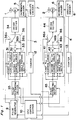
- Fig. 1 is a block diagram showing the construction of a multi-shaft driving apparatus according to the embodiment.
- the apparatus comprises motors M1 and M2 each for driving shafts 1 and 2 to be synchronously rotated; motor control circuits 3 and 4 for controlling the motors M1 and M2, respectively; incremental encoders 5 and 6 and absolute encoders 7 and 8, for detecting the rotational state of the shafts 1 and 2, namely, rotational position thereof and rotational speed thereof; a pulse generator 9, positioned in a front stage of the motor control circuits 3 and 4, for generating pulse signals for rotating the shafts 1 and 2; and a CPU control circuit 10 for outputting control signals to the motor control circuits 3 and 4 and to the pulse generator 9.
- the motor control circuits 3 comprises a first PLL control circuit 31; a second PLL control circuit 32; a rotational angle phasing circuit 33; a driver section 34 consisting of a current amplifier; and a pulse extracting section 35.
- the motor control circuits 4 comprises a first PLL control circuit 41; a second PLL control circuit 42; a rotational angle phasing circuit 43; a driver section 44 consisting of a current amplifier; and a pulse extracting section 45.
- the "PLL control" means a phase-locked loop control.
- Pulse signals, generated by the pulse generator 9, for rotating the shafts 1 and 2 and pulse signals detected by the incremental encoders 5 and 6 serving as feedback signals are inputted to the first and second PLL control circuits 31, 32, 41, and 42 and the rotational angle phasing sections 33 and 43 via the pulse extracting sections 35 and 45.
- the following three control loops (1), (2), and (3) are generated.
- First PLL control loop (1) passes through the first PLL control circuits 31 and 41.
- Second PLL control loop (2) passes through the second PLL control circuits 32 and 42.
- Rotational angle phasing control loop (3) passes through the rotational angle phasing sections 33 and 43.
- contacts of switching sections 36 and 46 are changed as follows to select a first state, a second state or a third state.
- contacts 36a and 46a are connected with the CPU control section 10
- the first state in which only the first PLL control loop (1) is generated is selected.
- contacts 36b and 46b are connected therewith, the second state in which the second PLL control loop (2) and the rotational angle phasing control loop (3) are generated is selected.
- contacts 36c and 46c are connected therewith, the third state in which only the rotational angle phasing control loop (3) is generated is selected.
- the PLL control circuits 31, 32, 41, and 42 detect the phase difference between the pulse signal, for rotating the shafts 1 and 2, outputted from the pulse generator 9 and the pulse signal detected by the incremental encoders 5 and 6 so that the frequency of both signals and the phase thereof are coincident with each other.
- the signal indicating the detected phase difference is used as a feedback control.
- both pulse signals are inputted to the PLL control circuits 31, 32, 41, and 42 and a phase compensation is made by detecting the phase difference between both pulse signals by a phase comparator and by passing a signal indicating the phase difference through a low-pass filter. Since this method is known, the description thereof is omitted.
- the pulse extracting sections 35 and 45 Upon receipt of an instruction of the CPU control section 10, the pulse extracting sections 35 and 45 extract the instructed number of pulses from pulse signals, for rotating the shafts 1 and 2, outputted from the pulse generator 9.
- the signal outputted from the absolute encoders 7 and 8 are converted into a signal indicating the rotational position of the shafts 1 and 2 by counters 12 and 13, and then the converted signal is inputted to the CPU control section 10.
- the phase difference between the rotational angle of the shafts 1 and 2 is adjusted to a predetermined phase difference.
- the state in which only the rotational angle phasing control loop (3) is generated is selected, i.e., the contacts 36c and 46c are selected.
- the CPU control section 10 issues to the pulse generator 9 an instruction of generating pulse signals, for rotating the shafts 1 and 2, of a low frequency.
- the CPU control section 10 controls the pulse extracting sections 35 and 45 so that the pulse generator 9 outputs a necessary number of pulses to the motor control circuits 3 and 4.
- the phase difference between the rotational angle of the shafts 1 and 2 is adjusted to the predetermined phase difference.
- the number of rotations of the shafts 1 and 2 is increased to that of the steady state with the phase difference between the rotational angle of the shafts 1 and 2 kept at the predetermined phase difference.
- the state in which the second PLL control loop (2) and the rotational angle phasing control loop (3) are generated in parallel is selected, i.e., the contacts 36b and 46b are selected.
- the frequency of the pulse signal, for rotating the shafts 1 and 2, outputted from the pulse generator 9 is gradually increased.
- the second PLL control loop (2) does not have a fast response to a great fluctuation of the frequency of the pulse signal and consequently, the second PLL control loop (2) alone is incapable of keeping the initially set phase difference between the rotational angle of the shafts 1 and 2.
- the rotational angle phasing control loop (3) has the following function.
- the rotational angle phasing sections 33 and 43 having a deviation counter respectively monitor the output of the incremental encoders 5 and 6 and instantly correct the deviation of the phase difference between the rotational angle of the shafts 1 and 2, thus accurately following the rise of the frequency of the pulse signal. That is, the rotational angle phasing control loop (3) performs the speed control of f/V conversion system.
- the shafts 1 and 2 can be synchronously rotated with a high accuracy even in the transient state.
- the state in which only the first PLL control loop (1) is generated is selected, i.e., the contacts 36a and 46a are selected.
- the frequency of the pulse signal for rotating the shafts 1 and 2 is almost constant. Therefore, even though the rotational angle phasing control loop (3) does not function, the phase difference between the rotational angle of the shafts 1 and 2 is kept at the predetermined phase difference.
- Another reason the rotational angle phasing control loop (3) is not allowed to operate in the steady state is as follows: In the steady state, an optimum control may be made by slightly varying the predetermined phase difference between the rotational angle of the shafts 1 and 2.
- the pulse extracting sections 35 and 45 extract a necessary number of pulses from the pulse signal for rotating the shafts 1 and 2. But if the rotational angle phasing control loop (3) functions, the varied phase difference returns to the predetermined phase difference. That is, the predetermined phase difference cannot be varied.
- the state in which the second PLL control loop (2) and the rotational angle phasing control loop (3) are generated in parallel is selected, i.e., the contacts 36b and 46b are selected.
- the frequency of the pulse signal for rotating the shafts 1 and 2 is gradually decreased.
- the second PLL control loop (2) has a fast response to a slight fluctuation of the frequency of the pulse signal, but does not have a fast response to a great fluctuation of the frequency thereof and consequently, the second PLL control loop (2) alone is incapable of keeping the predetermined phase difference between the rotational angle of the shafts 1 and 2 at the predetermined phase difference.
- the rotational angle phasing control loop (3) has the following function.
- the rotational angle phasing sections 33 and 43 having a deviation counter respectively monitor the output of the incremental encoders 5 and 6 and instantly correct the deviation of the phase difference between the rotational angle of the shafts 1 and 2, thus accurately following the fall of the frequency of the pulse signal.
- the shafts 1 and 2 can be synchronously rotated with a high accuracy even in the fall time.
- the CPU control section 10 monitors the signal, indicating the phase difference between the rotational angle of the shafts 1 and 2, detected by the absolute encoders 7 and 8 in the rise time and fall time of the shafts 1 and 2. If the CPU control section 10 detects a deviation in the phase difference between the rotational angle of the shafts 1 and 2, the CPU control section 10 controls the pulse extracting sections 35 and 45 so as to correct the frequency and phase of the pulse signal for rotating the shafts 1 and 2 and the deviated phase difference in the phase difference between the rotational angle of the shafts 1 and 2.
- the motor control circuits 3 and 4 have two PLL control circuits 31 and 32, and two PLL control circuits 41 and 42, respectively, but the motor control circuits 3 and 4 may include one PLL control circuit 32 and 42, respectively so that the output of the PLL control circuits 32 and 42 is directly connected to the contact 36a and 46a, respectively.
- the multi-shaft driving apparatus shown in Fig. 1 allows the shafts to be rotated synchronously not only in the steady state, but also in the transient state. Thus, the apparatus can be utilized in a wide range.
- Figs. 2 and 3 show a positive-displacement vacuum pump according to an embodiment of the present invention.
- Fig. 2 is a sectional view of the pump.
- Fig. 3 is a front view, showing the positive-displacement vacuum pump, in which a housing is broken away.
- the vacuum pump comprises a first bearing chamber 111 accommodating a first rotary shaft 102 vertically and a second bearing chamber 112 accommodating a second rotary shaft 103 vertically.
- Cylindrical rotors 104 and 105 are mounted on upper portions of the shafts 102 and 103, respectively.
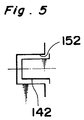
- Screws 142 and 152 are formed on the peripheral surfaces of the rotors 104 and 105, respectively so that the screws 142 and 152 engage each other.
- the engagement portion of the screws 142 and 152 is denoted by (A). That is, a closed space formed by the concave (groove) and convex of the engagement portion (A) of the screws 142 and 152 and the housing 101 changes its volume cyclically with the rotation of the shafts 102 and 103. Thus, fluid sucking and discharging operations are performed.
- gears 144 and 154 for preventing the contact of the screws 142 and 152 are formed on the peripheral surfaces of the rotors 104 and 105 at the lower end thereof.
- a solid lubricating film is formed on the gears 144 and 154 so that the metal of the gears 144 and 154 are capable of withstanding a small degree of contact.
- a gap (backlash) ⁇ 2 between the engagement portion of the gears 144 and 154 is set to be smaller than a gap (backlash) ⁇ 1 between the engagement portion (A) of the screws 142 and 152 formed on the peripheral surfaces of the rotors 104 and 105, respectively.
- the gears 144 and 154 do not contact each other when the shafts 102 and 103 are synchronously and smoothly rotating. If they are not rotating synchronously, the gears 144 and 154 contact each other, thus preventing the contact of the screws 142 and 152. If the amount of backlashes ⁇ 1 and ⁇ 2 is too small to be accurately processed for practical use.
- the total amount of fluid leakage during one process of the pump is proportional to the period of time required in the process. Therefore, while the shafts 102 and 103 are rotating at a high speed, the performance of the pump such as ultimate vacuum degree can be sufficiently maintained even though the backlash ⁇ 1 is made to be comparatively large. Accordingly, the dimension of the backlashes ⁇ 1 and ⁇ 2 necessary for preventing the collision of the screws 142 and 152 can be reliably obtained by rotating the shafts 1 and 2 at a high speed even though the processing accuracy of the screws is not high.
- a gas suction opening 114 and a gas discharge opening 115 are provided upstream and downstream of the engagement portion (A) of the housing 101, respectively.
- the shafts 102 and 103 are supported by a non-contact type static pressure bearing, which is described below, provided in internal spaces 145 and 155 of the rotors 104 and 105. That is, a thrust bearing is constituted by supplying compressed gas from orifices 116 to the upper and lower surfaces of the disks 121 and 131 formed on the shafts 102 and 103, respectively, and a radial bearing is composed by supplying compressed gas from orifices 117 to the peripheral surface of the shafts 102 and 103.
- the utilization of clean nitrogen gas equipped in a semi-conductor factory as compressed gas is capable of making the pressure inside the internal spaces 145 and 155 accommodating a motor higher than the atmospheric pressure. Thus, reactive gas which is corrosive and easily produces sediment can be prevented from penetrating into the internal spaces 145 and 155.
- the bearing may be composed of a magnetic bearing which is also of a non-contact type and as such oil-free. Therefore, the shafts 102 and 103 are capable of rotating at a high speed. If a ball bearing is used in the bearing portion (chamber) and lubricating oil is used to lubricate the ball bearing, a gas verge mechanism utilizing nitrogen gas is capable of preventing the penetration of lubricating oil into a fluid actuation chamber.
- Both the shafts 102 and 103 are rotated at a speed as high as tens of thousands of rpm by AC servo motors 107 and 106 provided each in a lower portion of the shafts 102 and 103.
- Encoders 108 and 109 are provided on the lower ends of the shafts 102 and 103 and correspond to the encoders 5,6,7, and 8 in Fig. 1.
- the phase difference between the rotational angles of the shafts 102 and 103 is adjusted to a predetermined phase difference under the control of the rotational angle phasing control loop (3) so that the center line of the convex or concave of the screw 142 and that of concave or convex of the screw 152 align with each other.
- the phase difference in the rotational angle between the shafts 1 and 2 can be adjusted to the predetermined phase difference by the gears 144 and 154.
- the number of the rotations of the shafts 102 and 103 is increased to that of the steady state with the phase difference in the rotational angle between the shafts 102 and 103 kept at the predetermined phase difference.
- the number of the rotations of the shafts 102 and 103 smoothly rises to that of the steady state in an accurate accordance with the number of rotations instructed by the pulse signal, for rotating the shafts 102 and 103, outputted from the pulse generator 9 without the gears 144 and 154 (screws 142 and 152) contacting each other.
- This is the above-described rise time operation of the multi-shaft driving apparatus.
- the first part of the rise time operation can be performed by the rotation of the gears 144 and 154 (screws 142 and 152).
- the shafts 102 and 103 are rotated synchronously with a high accuracy by the first PLL control loop (1).
- the rotation of the shafts 102 and 103 can be stopped in an accurate accordance with the number of rotations instructed by the pulse signal for rotating the shafts 102 and 103 without the contact of the gears 144 and 154 (screws 142 and 152). This is the above-described fall time operation of the multi-shaft driving apparatus.
- the vacuum pump is capable of rotating the shafts 102 and 103 or the screws 142 and 152 synchronously with a high accuracy not only in the steady state, but also in the transient state.
- the shafts 102 and 103 are not rotated synchronously by a timing gear. Therefore, it is unnecessary to use lubricating oil or an oil seal in the timing gear. Consequently, a clean vacuum without oil can be obtained. Since a mechanical sliding portion is not provided, the shafts 102 and 103 can be rotated at a high speed and in addition, the vacuum pump does not make a big noise and is durable. Further, the shafts 102 and 103 can be rotated at a higher speed and the pump can be compact by supporting the shafts 102 and 103 by the static gas bearing.
- the fluid rotary apparatus shown in Fig. 2 may be applied to a positive-displacement vacuum pump.
- the pump does not require the provision of a mechanical sliding portion which allows the shafts to be rotated synchronously both in the transient state (rise time and fall time) and in the steady state. That is, the pump does not require the supply of lubricating oil. Therefore, the pump is clean and the shafts (rotors) rotate at a high speed, and in addition, the apparatus is durable.
- the apparatus can include a vacuum degree setting means 160 for setting the vacuum degree in a discharge space and a vacuum degree detecting means 161 for detecting the vacuum degree therein.
- the frequency of the pulse signal indicating the number of rotations of the shafts 102 and 103 is varied according to the difference between a set vacuum degree and a detected vacuum degree.
- the number of rotations of the rotors 104 and 105 may be varied according to the detected vacuum degree in the discharge space.
- the number of rotations of the rotors 104 and 105 can be accurately controlled and consequently, gas can be accurately discharged in a wide vacuum range from a low vacuum degree to a high vacuum degree. Therefore, gas discharge performance can be controlled with a high accuracy.
- the control of the pressure in the vacuum chamber can be facilitated without using a butterfly valve.
- the fluid rotary apparatus is capable of discharging gas and controlling pressure with a high accuracy without providing the vacuum pump with a flow rate controlling equipment, for example, a butterfly valve.
- the phase difference between the rotational angles of the shafts 102 and 103 is adjusted to the predetermined phase difference so that the center line of the convex or concave of the screw 142 and that of the concave or convex of the screw 152 align with each other.
- the center line of the convex or concave of the screw 142 and that of the concave or convex of the screw 152 do not align with each other (for example, rotational angle difference of the shafts 102 and 103 is set to approximately 0.01°.)
- the pulse extracting sections 35 and 45 extract a necessary number of pulses from the pulse signal for rotating the shafts 102 and 103.
- the pulse extracting sections 35 and 45 are provided both in the motor control circuits 3 and 4 so that the center line of the convex or concave of the screw 142 and that of the concave or convex of the screw 152 do not align with each other in both backward and forward directions.
- an encoder having approximately 10,000 light transmitting slits per 360° (one rotation) is preferably used to obtain pulses of 40,000 resolutions, namely, four times as great as 10,000.
- 360°/40000 0.01°
Landscapes
- Engineering & Computer Science (AREA)
- Power Engineering (AREA)
- Human Computer Interaction (AREA)
- Manufacturing & Machinery (AREA)
- Physics & Mathematics (AREA)
- General Physics & Mathematics (AREA)
- Automation & Control Theory (AREA)
- Applications Or Details Of Rotary Compressors (AREA)
- Control Of Multiple Motors (AREA)
- Non-Positive Displacement Air Blowers (AREA)
Applications Claiming Priority (2)
| Application Number | Priority Date | Filing Date | Title |
|---|---|---|---|
| JP37223/91 | 1991-03-04 | ||
| JP3037223A JP3049793B2 (ja) | 1991-03-04 | 1991-03-04 | 流体回転装置 |
Publications (3)
| Publication Number | Publication Date |
|---|---|
| EP0502459A2 true EP0502459A2 (de) | 1992-09-09 |
| EP0502459A3 EP0502459A3 (en) | 1993-03-17 |
| EP0502459B1 EP0502459B1 (de) | 1997-07-09 |
Family
ID=12491597
Family Applications (1)
| Application Number | Title | Priority Date | Filing Date |
|---|---|---|---|
| EP92103558A Expired - Lifetime EP0502459B1 (de) | 1991-03-04 | 1992-03-02 | Mehrwellenantriebsvorrichtung und Fluiddrehvorrichtung |
Country Status (5)
| Country | Link |
|---|---|
| US (1) | US5329216A (de) |
| EP (1) | EP0502459B1 (de) |
| JP (1) | JP3049793B2 (de) |
| KR (1) | KR960004261B1 (de) |
| DE (1) | DE69220692T2 (de) |
Cited By (5)
| Publication number | Priority date | Publication date | Assignee | Title |
|---|---|---|---|---|
| WO1994029596A1 (de) * | 1993-06-04 | 1994-12-22 | Sihi Gmbh & Co. Kg. | Verdrängermaschine mit elektronischer motorsynchronisation |
| NL1005045C2 (nl) * | 1997-01-20 | 1998-07-22 | Buhrs Zaandam Bv | Besturingsinrichting. |
| EP0886068A3 (de) * | 1998-08-25 | 1999-03-17 | Maag Pump Systems Textron AG | Zahnradpumpe mit einem Mehrwellenantrieb |
| DE202009003981U1 (de) | 2009-03-24 | 2010-08-19 | Vacuubrand Gmbh + Co Kg | Antrieb für eine Vakuumpumpe |
| WO2018093440A1 (en) * | 2016-11-16 | 2018-05-24 | Carrier Corporation | Screw compressor with rotor synchronization |
Families Citing this family (27)
| Publication number | Priority date | Publication date | Assignee | Title |
|---|---|---|---|---|
| DE4322744C2 (de) * | 1993-07-08 | 1998-08-27 | Baumueller Nuernberg Gmbh | Elektrisches Antriebssystem und Positionierverfahren zur synchronen Verstellung mehrerer dreh- und/oder verschwenkbarer Funktionsteile in Geräten und Maschinen, Antriebsanordnung mit einem Winkellagegeber und Druckmaschine |
| DE59410249D1 (de) * | 1994-07-23 | 2003-04-03 | Baumueller Nuernberg Gmbh | Elektrisches Antriebssystem zur Vorstellung von einem oder mehreren dreh- und/oder verschwenkbaren Funktionsteilen in Geräten und Maschinen, Antriebsordnung mit einem Winkellagegeber und Druckmaschine |
| WO1997001037A1 (de) * | 1995-06-21 | 1997-01-09 | Sihi Industry Consult Gmbh | Vakuumpumpe |
| DE19522555A1 (de) * | 1995-06-21 | 1997-01-02 | Sihi Ind Consult Gmbh | Rotationskolbenverdichter mit zwei Rotoren |
| US5625267A (en) * | 1995-12-13 | 1997-04-29 | Coburn Optical Industries, Inc. | Constant delay filtering for synchronized motion on multiple axes |
| KR100611435B1 (ko) * | 1998-07-23 | 2006-08-09 | 가부시키가이샤 야스카와덴키 | 절대엔코더 |
| US6323614B1 (en) * | 1998-09-04 | 2001-11-27 | The Texas A&M University System | System and method for controlling suspension using a magnetic field |
| DE19955547A1 (de) * | 1999-11-18 | 2001-05-31 | Uwe Kischke | Rütteleinrichtung für Schalungskerne mit rotationssymmetischem Querschnitt |
| US7417392B2 (en) * | 2005-05-31 | 2008-08-26 | Rockwell Automation Technologies, Inc. | Electronic line shaft with phased lock loop filtering and predicting |
| US7428846B2 (en) * | 2006-12-21 | 2008-09-30 | Namco Machine & Gear Works Ltd. | Shaft encoder with anti-backlash gears |
| US20100322806A1 (en) * | 2009-06-18 | 2010-12-23 | Aregger Markus | Arrangement including a gear pump |
| DE102010019402A1 (de) * | 2010-05-04 | 2011-11-10 | Oerlikon Leybold Vacuum Gmbh | Schrauben-Vakuumpumpe |
| CN103104493B (zh) * | 2011-11-11 | 2015-12-09 | 中国科学院沈阳科学仪器股份有限公司 | 一种用于无油干式真空泵双驱动主轴控制系统 |
| WO2013121586A1 (ja) * | 2012-02-17 | 2013-08-22 | 三菱電機株式会社 | 放電加工機及び放電加工方法 |
| SG11201607066SA (en) | 2014-02-28 | 2016-09-29 | Project Phoenix Llc | Pump integrated with two independently driven prime movers |
| US10465721B2 (en) | 2014-03-25 | 2019-11-05 | Project Phoenix, LLC | System to pump fluid and control thereof |
| WO2015164453A2 (en) | 2014-04-22 | 2015-10-29 | Afshari Thomas | Fluid delivery system with a shaft having a through-passage |
| WO2015187681A1 (en) | 2014-06-02 | 2015-12-10 | Afshari Thomas | Hydrostatic transmission assembly and system |
| WO2015187673A1 (en) | 2014-06-02 | 2015-12-10 | Afshari Thomas | Linear actuator assembly and system |
| AU2015292611B2 (en) | 2014-07-22 | 2019-07-04 | Project Phoenix, LLC | External gear pump integrated with two independently driven prime movers |
| US10072676B2 (en) * | 2014-09-23 | 2018-09-11 | Project Phoenix, LLC | System to pump fluid and control thereof |
| EP3204647B1 (de) * | 2014-10-06 | 2021-05-26 | Project Phoenix LLC | Linearaktuatoranordnung und -system |
| US10677352B2 (en) | 2014-10-20 | 2020-06-09 | Project Phoenix, LLC | Hydrostatic transmission assembly and system |
| US11085440B2 (en) | 2015-09-02 | 2021-08-10 | Project Phoenix, LLC | System to pump fluid and control thereof |
| TWI768455B (zh) | 2015-09-02 | 2022-06-21 | 美商鳳凰計劃股份有限公司 | 泵送流體之系統及其控制 |
| EP4179211A1 (de) | 2020-07-08 | 2023-05-17 | Project Phoenix, LLC | Dynamische steuerung von zahnrädern in einer zahnradpumpe mit einer antriebskonfiguration |
| US12535071B2 (en) | 2020-07-08 | 2026-01-27 | Project Phoenix, LLC | Dynamic control of gears in a gear pump having a drive-drive configuration |
Family Cites Families (8)
| Publication number | Priority date | Publication date | Assignee | Title |
|---|---|---|---|---|
| DE2163474A1 (de) * | 1971-12-21 | 1973-06-28 | Philips Patentverwaltung | Schaltungsanordnung zur synchronisation elektrischer antriebe |
| US4048657A (en) * | 1975-12-22 | 1977-09-13 | Teletype Corporation | Method and apparatus for synchronizing a facsimile transmission |
| CH659290A5 (de) * | 1982-07-08 | 1987-01-15 | Maag Zahnraeder & Maschinen Ag | Zahnradpumpe. |
| JPS5969765A (ja) * | 1982-10-15 | 1984-04-20 | Canon Inc | 回転体駆動装置 |
| JPS5981712A (ja) * | 1982-11-02 | 1984-05-11 | Canon Inc | 制御方式 |
| US4659283A (en) * | 1985-09-30 | 1987-04-21 | United Technologies Corporation | Propeller Synchrophaser® device and mode logic |
| JP2858319B2 (ja) * | 1989-01-30 | 1999-02-17 | 松下電器産業株式会社 | 多軸同期駆動装置及び歯車加工装置 |
| JPH0744864B2 (ja) * | 1989-05-22 | 1995-05-15 | シャープ株式会社 | Pll速度制御回路 |
-
1991
- 1991-03-04 JP JP3037223A patent/JP3049793B2/ja not_active Expired - Lifetime
-
1992
- 1992-03-02 DE DE69220692T patent/DE69220692T2/de not_active Expired - Lifetime
- 1992-03-02 EP EP92103558A patent/EP0502459B1/de not_active Expired - Lifetime
- 1992-03-04 KR KR1019920003570A patent/KR960004261B1/ko not_active Expired - Fee Related
-
1993
- 1993-06-01 US US08/070,038 patent/US5329216A/en not_active Expired - Lifetime
Cited By (9)
| Publication number | Priority date | Publication date | Assignee | Title |
|---|---|---|---|---|
| WO1994029596A1 (de) * | 1993-06-04 | 1994-12-22 | Sihi Gmbh & Co. Kg. | Verdrängermaschine mit elektronischer motorsynchronisation |
| AU688336B2 (en) * | 1993-06-04 | 1998-03-12 | Sihi Gmbh & Co Kg | Positive displacement machine with electronic motor synchronisation |
| US5767635A (en) * | 1993-06-04 | 1998-06-16 | Sihi Gmbh & Co. Kg | Displacement machine with electronic motor synchronization |
| NL1005045C2 (nl) * | 1997-01-20 | 1998-07-22 | Buhrs Zaandam Bv | Besturingsinrichting. |
| EP0886068A3 (de) * | 1998-08-25 | 1999-03-17 | Maag Pump Systems Textron AG | Zahnradpumpe mit einem Mehrwellenantrieb |
| US6312225B1 (en) | 1998-08-25 | 2001-11-06 | Maag Pump Systems Textron Ag | Gear pump having a multishaft drive and method of operating same |
| US6447256B2 (en) | 1998-08-25 | 2002-09-10 | Maag Pump Systems Textron, Ag | Gear pump having a multishaft drive and method of operating same |
| DE202009003981U1 (de) | 2009-03-24 | 2010-08-19 | Vacuubrand Gmbh + Co Kg | Antrieb für eine Vakuumpumpe |
| WO2018093440A1 (en) * | 2016-11-16 | 2018-05-24 | Carrier Corporation | Screw compressor with rotor synchronization |
Also Published As
| Publication number | Publication date |
|---|---|
| EP0502459B1 (de) | 1997-07-09 |
| DE69220692D1 (de) | 1997-08-14 |
| EP0502459A3 (en) | 1993-03-17 |
| US5329216A (en) | 1994-07-12 |
| KR920019057A (ko) | 1992-10-22 |
| KR960004261B1 (ko) | 1996-03-28 |
| JP3049793B2 (ja) | 2000-06-05 |
| DE69220692T2 (de) | 1998-02-19 |
| JPH04275089A (ja) | 1992-09-30 |
Similar Documents
| Publication | Publication Date | Title |
|---|---|---|
| US5329216A (en) | Multi-shaft driving apparatus and fluid rotary apparatus | |
| US5393201A (en) | Synchronous rotating apparatus for rotating a plurality of shafts | |
| US5197861A (en) | Fluid rotating apparatus | |
| JPH05263769A (ja) | 流体回転装置 | |
| US5271719A (en) | Fluid rotating apparatus and method of controlling the same | |
| US5295798A (en) | Fluid rotating apparatus with rotor communicating path | |
| US5352097A (en) | Vacuum pump | |
| KR100201423B1 (ko) | 진공펌프 | |
| US5478210A (en) | Multi-stage vacuum pump | |
| US5674051A (en) | Positive displacement pump having synchronously rotated non-circular rotors | |
| US6485274B2 (en) | Displacement machine for compressible media | |
| US5314312A (en) | Fluid-rotating apparatus | |
| KR0130052B1 (ko) | 유체회전장치 | |
| US5417551A (en) | Housing arrangement for a synchronous plural motor fluid rotary apparatus | |
| US5354179A (en) | Fluid rotating apparatus | |
| KR0130049B1 (ko) | 유체회전장치 | |
| JP3435716B2 (ja) | 複数軸の同期回転装置 | |
| EP0691475B1 (de) | Drehkolbenanlage für flüssige Medien | |
| JP2981512B2 (ja) | 真空ポンプ | |
| JP2996223B2 (ja) | 真空ポンプ | |
| JPH0646590A (ja) | 流体回転装置 | |
| JPH05332258A (ja) | 流体回転装置 | |
| JP2000018169A (ja) | 真空ポンプ |
Legal Events
| Date | Code | Title | Description |
|---|---|---|---|
| PUAI | Public reference made under article 153(3) epc to a published international application that has entered the european phase |
Free format text: ORIGINAL CODE: 0009012 |
|
| 17P | Request for examination filed |
Effective date: 19920302 |
|
| AK | Designated contracting states |
Kind code of ref document: A2 Designated state(s): DE FR GB |
|
| PUAL | Search report despatched |
Free format text: ORIGINAL CODE: 0009013 |
|
| AK | Designated contracting states |
Kind code of ref document: A3 Designated state(s): DE FR GB |
|
| 17Q | First examination report despatched |
Effective date: 19941010 |
|
| GRAG | Despatch of communication of intention to grant |
Free format text: ORIGINAL CODE: EPIDOS AGRA |
|
| GRAH | Despatch of communication of intention to grant a patent |
Free format text: ORIGINAL CODE: EPIDOS IGRA |
|
| GRAH | Despatch of communication of intention to grant a patent |
Free format text: ORIGINAL CODE: EPIDOS IGRA |
|
| GRAA | (expected) grant |
Free format text: ORIGINAL CODE: 0009210 |
|
| AK | Designated contracting states |
Kind code of ref document: B1 Designated state(s): DE FR GB |
|
| ET | Fr: translation filed | ||
| REF | Corresponds to: |
Ref document number: 69220692 Country of ref document: DE Date of ref document: 19970814 |
|
| PLBE | No opposition filed within time limit |
Free format text: ORIGINAL CODE: 0009261 |
|
| STAA | Information on the status of an ep patent application or granted ep patent |
Free format text: STATUS: NO OPPOSITION FILED WITHIN TIME LIMIT |
|
| 26N | No opposition filed | ||
| REG | Reference to a national code |
Ref country code: GB Ref legal event code: IF02 |
|
| PGFP | Annual fee paid to national office [announced via postgrant information from national office to epo] |
Ref country code: FR Payment date: 20090316 Year of fee payment: 18 |
|
| REG | Reference to a national code |
Ref country code: GB Ref legal event code: 746 Effective date: 20091215 |
|
| PGFP | Annual fee paid to national office [announced via postgrant information from national office to epo] |
Ref country code: GB Payment date: 20100224 Year of fee payment: 19 |
|
| PGFP | Annual fee paid to national office [announced via postgrant information from national office to epo] |
Ref country code: DE Payment date: 20100312 Year of fee payment: 19 |
|
| REG | Reference to a national code |
Ref country code: FR Ref legal event code: ST Effective date: 20101130 |
|
| PG25 | Lapsed in a contracting state [announced via postgrant information from national office to epo] |
Ref country code: FR Free format text: LAPSE BECAUSE OF NON-PAYMENT OF DUE FEES Effective date: 20100331 |
|
| GBPC | Gb: european patent ceased through non-payment of renewal fee |
Effective date: 20110302 |
|
| PG25 | Lapsed in a contracting state [announced via postgrant information from national office to epo] |
Ref country code: DE Free format text: LAPSE BECAUSE OF NON-PAYMENT OF DUE FEES Effective date: 20111001 |
|
| REG | Reference to a national code |
Ref country code: DE Ref legal event code: R119 Ref document number: 69220692 Country of ref document: DE Effective date: 20111001 |
|
| PG25 | Lapsed in a contracting state [announced via postgrant information from national office to epo] |
Ref country code: GB Free format text: LAPSE BECAUSE OF NON-PAYMENT OF DUE FEES Effective date: 20110302 |