EP0502836A2 - Radiateur pour moteur à combustion interne - Google Patents
Radiateur pour moteur à combustion interne Download PDFInfo
- Publication number
- EP0502836A2 EP0502836A2 EP92850049A EP92850049A EP0502836A2 EP 0502836 A2 EP0502836 A2 EP 0502836A2 EP 92850049 A EP92850049 A EP 92850049A EP 92850049 A EP92850049 A EP 92850049A EP 0502836 A2 EP0502836 A2 EP 0502836A2
- Authority
- EP
- European Patent Office
- Prior art keywords
- side members
- header box
- header
- engagement
- boxes
- Prior art date
- Legal status (The legal status is an assumption and is not a legal conclusion. Google has not performed a legal analysis and makes no representation as to the accuracy of the status listed.)
- Granted
Links
Images




Classifications
-
- F—MECHANICAL ENGINEERING; LIGHTING; HEATING; WEAPONS; BLASTING
- F28—HEAT EXCHANGE IN GENERAL
- F28F—DETAILS OF HEAT-EXCHANGE AND HEAT-TRANSFER APPARATUS, OF GENERAL APPLICATION
- F28F9/00—Casings; Header boxes; Auxiliary supports for elements; Auxiliary members within casings
- F28F9/001—Casings in the form of plate-like arrangements; Frames enclosing a heat exchange core
-
- F—MECHANICAL ENGINEERING; LIGHTING; HEATING; WEAPONS; BLASTING
- F28—HEAT EXCHANGE IN GENERAL
- F28F—DETAILS OF HEAT-EXCHANGE AND HEAT-TRANSFER APPARATUS, OF GENERAL APPLICATION
- F28F2275/00—Fastening; Joining
- F28F2275/08—Fastening; Joining by clamping or clipping
- F28F2275/085—Fastening; Joining by clamping or clipping with snap connection
Definitions
- the present invention concerns a radiator for an internal combustion engine, and more particularly for an internal combustion engine of a heavy vehicle, including upper and lower header boxes, each having first and second ends, and side members, each having first and second ends adapted to be connected to a respective one of said first and second ends of said header boxes to form therewith a relatively rigid frame, and, enclosed within said frame, a cooling block including a plurality of tubes communicating with their respective ends with said upper and lower header boxes for directing a flow of cooling fluid therebetween, a first of said header boxes having first engagement means at each of said first and second ends thereof, each of said side members having second engagement means at said first end thereof for releasable engagement with said first engagement means of said first header box.
- a radiator of this general kind is disclosed in EP-A1-0 346 602.
- a first header box of this known radiator is connected to a first end of a side member by hinge-like engagement means and snap-action engagement means
- the second header box is connected to the second end of the side member by a snap-action locking device.
- this radiator utilizes a separate wedge introduced between the side member at its second end and the header box after locking of the locking device.
- the header boxes are provided with several protrusions and the side members with corresponding recesses which inter-engage in the assembled position of the radiator.
- radiators are exposed to thermal stresses due to widely varying internal temperatures during operation of the engine, e.g., from far below the freezing point up to the boiling point of water, as well as temperature differentials between the radiator and the environment. Radiators are also exposed to stresses caused by vibrations due to engine running and vehicle driving.
- Temperature variations cause longitudinal expansion and contraction of the cooling fluid tubes leading to stresses in the connections between the header boxes and the lateral members.
- US-A-4 540 044 proposes a solution of this problem by providing oblong holes for pins connecting the header boxes and the lateral members, said holes having their maximum transverse dimension extending in the longitudinal direction of the tubes, thereby to accomodate relative movements between the header boxes and the lateral members.
- FR-A-2 538 030 proposes another solution of the same problem by providing the tube plates of the header boxes with deformable portions such that said portions, where the tubes are fastened to the tube plates, may move without transferring movement to the header boxes, and, thus, without affecting the distance between the header boxes defined by the lateral members rigidly connected thereto.
- resilient means are provided between the lateral members and outer mounting members extending in the longitudinal direction of the lateral members. Threaded bars extend between the outer mounting members to exert a pulling force therebetween, thereby to keep the radiator package together.
- the outer mounting members are secured to the header boxes by means of screws extending through holes provided in the mounting members and the header boxes.
- EP-B-0 020 190 proposes a solution of the vibrational stress problem by completely enclosing the assembled radiator in a multi-piece frame or cradle.
- Resilient means are interposed in the corners between the radiator and the frame such that the resilient means are tensioned and keep the radiator under permanent compression.
- the complete radiator package is kept together by means of bolts and spot welds.
- US-A-4 738 308 discloses an arrangement allowing compensation of differential dilatations which can occur between the cooling fluid tubes and the lateral members, or, flanges, due to different temperatures.
- the lateral members are generally C-shaped sections having a bottom, lateral sides and inwardly bent wings, the latter being engaged in notches provided in fins in which the tubes are engaged. Assembly of the header boxes and the side members of this prior art radiator includes plastic deformation, i.e., bending, of lugs provided on the lateral members.
- All the four prior art structures last referred to above employ some kind of more or less permanent fastening or securing means to attach the side members to the header boxes, such as pins, threaded bars, welds and bent lugs, all increasing the manufacturing costs due to material and labour required.
- the problem to be solved by the present invention is to provide a radiator of the kind initially stated, and particularly a connection between a side member and the header boxes of such a radiator, which - as taught by EP-A1-0 346 602 - widely avoids the use of fastening means, such as bolts or pins, or post-assembly treatment, such as welding or soldering, for obtaining a secure and releasable connection still allowing expansion and contraction of the radiator package due to heat variations.
- fastening means such as bolts or pins, or post-assembly treatment, such as welding or soldering
- the use of fastening means shall be completely avoided.
- there shall be no need of separate mounting means, such as the wedge according to EP-A1-0 346 602 and the solution shall provide compensation for manufacturing tolerances and reduce vibration transmission between the side member and the header box.
- a radiator as initially stated is characterized in that said first engagement means and said second engagement means are adapted, when mutually engaged, to allow displacement of said first ends of said side members substantially perpendicularly to the longitudinal direction of said first header box and to prevent displacement in other directions, that a second of said header boxes has first guide means at each of its first and second ends, that each of said side members has second guide means at its second end, said first and second guide means being adapted, when mutually releasably engaged, to allow displacement of said second ends of said side members substantially in the longitudinal direction of said second header box and to prevent displacement in other directions, and that resilient means is interposed between said coolimg block and said side members at said first end thereof, said resilient means being compressed between said first ends of said side members and said cooler block upon displacement of said second ends of said side members towards each other along said first guide means.
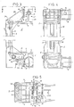
- the assembled outer structure of the radiator shown in the drawings includes two equally shaped header boxes, an upper header box 1 having in its mounted position an inverted U-shaped section (Fig. 4, upper part) and a lower header box 2 having a U-shaped section (Fig. 4, lower part), and two equally shaped side members, a first side member 3 and a second side member 4, the header boxes and the side members forming in their mounted position according to Fig. 1 a relatively rigid frame.
- a cooling block 5 (not shown in detail), conventionally having a plurality of vertically extending tubes, the upper and lower ends of which being fluid tightly engaged in a respective one of upper and lower tube plates 6 and 7.
- Tube plates 6 and 7 have lugs 6′, 7′, respectively, folded around circumferential rims 1′, 2′ of the header boxes, thereby closing the respective open U-section of the upper and lower header boxes 1 and 2 so as to form in each header box a fluid chamber.
- a cooling fluid introduced through an upper header box inlet 8 communicating with an internal combustion engine not shown, is distributed within the interior of the upper header box and directed downwards through the plurality of tubes to be collected in the lower header box and returned to the engine through an outlet 9.
- the header boxes are equally shaped, preferably being molded from a thermoplastic synthetic material in one and the same mould, and, thus, in their mounted positions, one header box is turned upside down and rotated 180° relative to the other header box. Consequently, the inlet 8 of the upper header box and the outlet 9 of the lower header box are corresponding portions of the respective header box located near one end thereof. Near the other end of the respective header box is formed a threaded hole in which is fitted a nipple 10 in the upper header box for ventilating the radiator system, and, in the lower header box a plug 11.
- Side member 3 has a generally U-shaped section comprising a web portion 12 and two flange portions 13, 14, the U-section being open towards the non-shown cooling block.
- the flange portions 13, 14 are obliquely extended lengthwise beyond the web portion 12 and inwardly towards the vertical centre of the radiator to form wings 15, 16 terminating in vertical lugs 17, 18, respectively, bent 90° relative to the respective wing 15, 16 (Fig. 5).
- the flange portions 13, 14 extend inwardly to form wings 19, 20, respectively, horizontal lower edges of which are bent 90° towards each other to form horizontal lugs 21, 22, respectively (Fig. 6).
- the U-shaped sections of the header boxes have substantially parallel outer side walls 23, 24 terminating in the above-mentioned circumferential rims 1′,2′, and, respectively, a flat outer top and bottom wall 25 having lengthwise and crosswise extending integral reinforcement ribs 26, 27.
- the ends of the U-shaped sections are closed by inclined walls 28 the inclination of which substantially corresponds to the inclination of the upper wings 15, 16.
- the vertical slots 32 are dimensioned to receive the vertical lugs 17, 18 and the horizontal slots 33 to receive the horizontal lugs 21, 22 of the upper and lower wings, respectively, of the side member.
- a resilient element 34 is inserted between the upper portion of each side member 3, 4 and the respective end of the upper header box 1.
- the position of such resilient element 34 is shown in Fig. 3.
- element 34 is U-shaped in a vertical cross-section (Fig, 12a) so as to grip around an end portion of header box 1, or, header plate 6 and its lugs 6′ folded around the circumferential rim 1′ of the header box, thereby to be kept in place during the assembly.
- element 34 has a U-shaped horizontal cross-section (Fig. 5), thereby to grip around the corners of the rim of the header box.
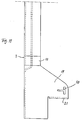
- the dimension of the resilient element 34 is such that it is compressed between the side member and the header box during assembly, starting approximately in the position of Fig. 12b and increasing towards full compression in the position of Fig. 12c. Both ends of side member 3, thus, will be urged outwardly by element 34, movement of the upper end of side member, however, being positively prevented by the engagement of the vertical lugs 17, 18 in the vertical slots 32 of the upper header box.
- the lower end of side member 3 is blocked against movement due to expansion of resilient element 34 by means of a conventional bolt 35 inserted in corresponding holes through side member 3 and lower header box 2, such hole 36 through lower header box being shown in Fig. 7.
- the second embodiment of the present invention according to Figs. 8 - 12 differs from the first embodiment according to Figs. 1 - 7 only regarding retainment of the lower ends of the side members to the ends of the lower header box 2. According to the second embodiment, thus, the lower ends of side members and the ends of the lower header box are provided with interengaging means to establish a snap-action locking connection between the side member and the header box.
- the side walls 23, 24 of the header boxes are formed with integral engagement means 37 having a T-shaped configuration when viewed in Fig. 9 including an inclined cam surface portion 38 (Fig. 8) and an abuttment portion 39 perpendicular thereto and also perpendicular to the respective side wall of the header box.
- the lower wings 19, 20 of the side members are provided with T-shaped openings 40 (Fig. 11) adapted to receive the abuttment portion 39 and a portion of the cam surface portion 38.
Landscapes
- Engineering & Computer Science (AREA)
- Physics & Mathematics (AREA)
- Thermal Sciences (AREA)
- Mechanical Engineering (AREA)
- General Engineering & Computer Science (AREA)
- Cooling, Air Intake And Gas Exhaust, And Fuel Tank Arrangements In Propulsion Units (AREA)
Applications Claiming Priority (2)
| Application Number | Priority Date | Filing Date | Title |
|---|---|---|---|
| SE9100674A SE508658C2 (sv) | 1991-03-06 | 1991-03-06 | Kylare med sidostycke försett med ingreppsorgan för lösbart ingrepp med kylartankarna |
| SE9100674 | 1991-03-06 |
Publications (3)
| Publication Number | Publication Date |
|---|---|
| EP0502836A2 true EP0502836A2 (fr) | 1992-09-09 |
| EP0502836A3 EP0502836A3 (en) | 1993-02-24 |
| EP0502836B1 EP0502836B1 (fr) | 1995-01-25 |
Family
ID=20382084
Family Applications (1)
| Application Number | Title | Priority Date | Filing Date |
|---|---|---|---|
| EP92850049A Expired - Lifetime EP0502836B1 (fr) | 1991-03-06 | 1992-03-06 | Radiateur pour moteur à combustion interne |
Country Status (4)
| Country | Link |
|---|---|
| EP (1) | EP0502836B1 (fr) |
| DE (1) | DE69201254T2 (fr) |
| ES (1) | ES2067320T3 (fr) |
| SE (1) | SE508658C2 (fr) |
Cited By (4)
| Publication number | Priority date | Publication date | Assignee | Title |
|---|---|---|---|---|
| FR2697907A1 (fr) * | 1992-11-09 | 1994-05-13 | Valeo Thermique Moteur Sa | Echangeur de chaleur à boîtes à eau reliées par des montants, notamment pour véhicule automobile. |
| FR2706994A1 (en) * | 1993-06-24 | 1994-12-30 | Valeo Thermique Moteur Sa | Heat exchanger with water (header) boxes connected by uprights |
| WO1999047875A1 (fr) * | 1998-03-14 | 1999-09-23 | Grayson Automotive Services Limited | Ensembles d'echangeurs de chaleur pour vehicules |
| DE102006037761A1 (de) * | 2006-08-11 | 2008-02-14 | Volkswagen Ag | Befestigungsanordnung für einen Ladeluftkühler und einen Wasserkühler |
Families Citing this family (1)
| Publication number | Priority date | Publication date | Assignee | Title |
|---|---|---|---|---|
| DE102005040607A1 (de) * | 2005-08-27 | 2007-03-15 | Behr Gmbh & Co. Kg | Anordnung zur Befestigung eines Wärmeübertragers an einem anderen |
Family Cites Families (2)
| Publication number | Priority date | Publication date | Assignee | Title |
|---|---|---|---|---|
| US1784766A (en) * | 1928-06-23 | 1930-12-09 | Gen Motors Corp | Radiator mounting |
| DE3428857A1 (de) * | 1984-08-04 | 1986-02-13 | Süddeutsche Kühlerfabrik Julius Fr. Behr GmbH & Co KG, 7000 Stuttgart | Wasser/luft-kuehler fuer wassergekuehlte verbrennungskraftmaschinen |
-
1991
- 1991-03-06 SE SE9100674A patent/SE508658C2/sv not_active IP Right Cessation
-
1992
- 1992-03-06 DE DE69201254T patent/DE69201254T2/de not_active Expired - Fee Related
- 1992-03-06 ES ES92850049T patent/ES2067320T3/es not_active Expired - Lifetime
- 1992-03-06 EP EP92850049A patent/EP0502836B1/fr not_active Expired - Lifetime
Cited By (6)
| Publication number | Priority date | Publication date | Assignee | Title |
|---|---|---|---|---|
| FR2697907A1 (fr) * | 1992-11-09 | 1994-05-13 | Valeo Thermique Moteur Sa | Echangeur de chaleur à boîtes à eau reliées par des montants, notamment pour véhicule automobile. |
| EP0597767A1 (fr) * | 1992-11-09 | 1994-05-18 | Valeo Thermique Moteur | Echangeur de chaleur à boîtes à eau reliées par des montants notamment pour véhicule automobile |
| FR2706994A1 (en) * | 1993-06-24 | 1994-12-30 | Valeo Thermique Moteur Sa | Heat exchanger with water (header) boxes connected by uprights |
| WO1999047875A1 (fr) * | 1998-03-14 | 1999-09-23 | Grayson Automotive Services Limited | Ensembles d'echangeurs de chaleur pour vehicules |
| DE102006037761A1 (de) * | 2006-08-11 | 2008-02-14 | Volkswagen Ag | Befestigungsanordnung für einen Ladeluftkühler und einen Wasserkühler |
| DE102006037761B4 (de) | 2006-08-11 | 2018-08-30 | Volkswagen Ag | Befestigungsanordnung für einen Ladeluftkühler und einen Wasserkühler |
Also Published As
| Publication number | Publication date |
|---|---|
| ES2067320T3 (es) | 1995-03-16 |
| DE69201254T2 (de) | 1995-06-22 |
| EP0502836B1 (fr) | 1995-01-25 |
| SE508658C2 (sv) | 1998-10-26 |
| EP0502836A3 (en) | 1993-02-24 |
| DE69201254D1 (de) | 1995-03-09 |
| SE9100674D0 (sv) | 1991-03-06 |
| SE9100674L (sv) | 1992-09-07 |
Similar Documents
| Publication | Publication Date | Title |
|---|---|---|
| US7121369B2 (en) | Frame for multiple vehicle heat exchangers | |
| US4540044A (en) | Radiator arrangement | |
| US4738308A (en) | Mechanically assembled heat exchanger of the tube and fin type | |
| US6330747B1 (en) | Heat exchanger assembly utilizing grommets and integral cast tanks | |
| US4191244A (en) | Modular heat exchanger with resilient mounting and sealing element | |
| JP3388354B2 (ja) | 複数の管列を有する特に自動車に適する熱交換器 | |
| EP0102715A2 (fr) | Echangeurs de chaleur | |
| US5228511A (en) | Motor vehicle heat exchanger having two interconnected water boxes | |
| US20040250988A1 (en) | Heat exchanger block | |
| EP0724129B1 (fr) | Boítes pour montage d'un échangeur de chaleur et procédé pour sa fabrication | |
| EP0502836B1 (fr) | Radiateur pour moteur à combustion interne | |
| US5195581A (en) | Snap on radiator tank | |
| US5355944A (en) | Heat exchanger comprising a bundle of finned tubes immobilized with respect to a collector header assembly | |
| US5111877A (en) | Multi-tube heat exchanger with mechanically interlocked tubes formed from mechanically interlocked plates | |
| US5613550A (en) | Tank for a heat exchanger | |
| GB2048451A (en) | Tubular heat exchangers | |
| GB2116687A (en) | Flat tube heat exchanger | |
| KR102780707B1 (ko) | 차량 엔진룸의 배열체 | |
| US5630472A (en) | Heat exchanger with a bundle of tubes and a metallic tube plate | |
| US6953080B2 (en) | Front end structure of vehicle preventing short-circuit of cooling air | |
| JPH0989490A (ja) | 積層型熱交換器 | |
| EP0777097B1 (fr) | Echangeur de chaleur, en particulier radiateur pour véhicule, muni d'une structure de renforçement | |
| LU102292B1 (en) | Cooling module and method for assembling a cooling module | |
| JPH0722350Y2 (ja) | 熱交換器の取付け構造 | |
| US2847191A (en) | Radiator for motor vehicles |
Legal Events
| Date | Code | Title | Description |
|---|---|---|---|
| PUAI | Public reference made under article 153(3) epc to a published international application that has entered the european phase |
Free format text: ORIGINAL CODE: 0009012 |
|
| AK | Designated contracting states |
Kind code of ref document: A2 Designated state(s): DE ES FR GB IT |
|
| PUAL | Search report despatched |
Free format text: ORIGINAL CODE: 0009013 |
|
| AK | Designated contracting states |
Kind code of ref document: A3 Designated state(s): DE ES FR GB IT |
|
| 17P | Request for examination filed |
Effective date: 19930625 |
|
| 17Q | First examination report despatched |
Effective date: 19940330 |
|
| GRAA | (expected) grant |
Free format text: ORIGINAL CODE: 0009210 |
|
| RAP1 | Party data changed (applicant data changed or rights of an application transferred) |
Owner name: VALEO ENGINE COOLING AKTIEBOLAG |
|
| AK | Designated contracting states |
Kind code of ref document: B1 Designated state(s): DE ES FR GB IT |
|
| REF | Corresponds to: |
Ref document number: 69201254 Country of ref document: DE Date of ref document: 19950309 |
|
| ET | Fr: translation filed | ||
| REG | Reference to a national code |
Ref country code: ES Ref legal event code: FG2A Ref document number: 2067320 Country of ref document: ES Kind code of ref document: T3 |
|
| ITF | It: translation for a ep patent filed | ||
| PLBE | No opposition filed within time limit |
Free format text: ORIGINAL CODE: 0009261 |
|
| 26N | No opposition filed | ||
| PGFP | Annual fee paid to national office [announced via postgrant information from national office to epo] |
Ref country code: GB Payment date: 19990226 Year of fee payment: 8 |
|
| PGFP | Annual fee paid to national office [announced via postgrant information from national office to epo] |
Ref country code: ES Payment date: 19990316 Year of fee payment: 8 |
|
| PG25 | Lapsed in a contracting state [announced via postgrant information from national office to epo] |
Ref country code: GB Free format text: LAPSE BECAUSE OF NON-PAYMENT OF DUE FEES Effective date: 20000306 |
|
| PG25 | Lapsed in a contracting state [announced via postgrant information from national office to epo] |
Ref country code: ES Free format text: LAPSE BECAUSE OF NON-PAYMENT OF DUE FEES Effective date: 20000307 |
|
| GBPC | Gb: european patent ceased through non-payment of renewal fee |
Effective date: 20000306 |
|
| REG | Reference to a national code |
Ref country code: ES Ref legal event code: FD2A Effective date: 20010910 |
|
| PGFP | Annual fee paid to national office [announced via postgrant information from national office to epo] |
Ref country code: FR Payment date: 20070330 Year of fee payment: 16 |
|
| PGFP | Annual fee paid to national office [announced via postgrant information from national office to epo] |
Ref country code: IT Payment date: 20080326 Year of fee payment: 17 |
|
| PGFP | Annual fee paid to national office [announced via postgrant information from national office to epo] |
Ref country code: DE Payment date: 20080311 Year of fee payment: 17 |
|
| REG | Reference to a national code |
Ref country code: FR Ref legal event code: TP Ref country code: FR Ref legal event code: CD |
|
| REG | Reference to a national code |
Ref country code: FR Ref legal event code: ST Effective date: 20091130 |
|
| PG25 | Lapsed in a contracting state [announced via postgrant information from national office to epo] |
Ref country code: DE Free format text: LAPSE BECAUSE OF NON-PAYMENT OF DUE FEES Effective date: 20091001 |
|
| PG25 | Lapsed in a contracting state [announced via postgrant information from national office to epo] |
Ref country code: FR Free format text: LAPSE BECAUSE OF NON-PAYMENT OF DUE FEES Effective date: 20091123 |
|
| PG25 | Lapsed in a contracting state [announced via postgrant information from national office to epo] |
Ref country code: IT Free format text: LAPSE BECAUSE OF NON-PAYMENT OF DUE FEES Effective date: 20090306 |
|
| PG25 | Lapsed in a contracting state [announced via postgrant information from national office to epo] |
Ref country code: FR Free format text: LAPSE BECAUSE OF NON-PAYMENT OF DUE FEES Effective date: 20090331 |