EP0503323A2 - Interface pour bus série et le procédé - Google Patents
Interface pour bus série et le procédé Download PDFInfo
- Publication number
- EP0503323A2 EP0503323A2 EP92102777A EP92102777A EP0503323A2 EP 0503323 A2 EP0503323 A2 EP 0503323A2 EP 92102777 A EP92102777 A EP 92102777A EP 92102777 A EP92102777 A EP 92102777A EP 0503323 A2 EP0503323 A2 EP 0503323A2
- Authority
- EP
- European Patent Office
- Prior art keywords
- bus
- signal
- applying
- bytes
- data
- Prior art date
- Legal status (The legal status is an assumption and is not a legal conclusion. Google has not performed a legal analysis and makes no representation as to the accuracy of the status listed.)
- Withdrawn
Links
Images

Classifications
-
- H—ELECTRICITY
- H04—ELECTRIC COMMUNICATION TECHNIQUE
- H04L—TRANSMISSION OF DIGITAL INFORMATION, e.g. TELEGRAPHIC COMMUNICATION
- H04L12/00—Data switching networks
- H04L12/28—Data switching networks characterised by path configuration, e.g. LAN [Local Area Networks] or WAN [Wide Area Networks]
- H04L12/40—Bus networks
- H04L12/40006—Architecture of a communication node
- H04L12/40013—Details regarding a bus controller
-
- H—ELECTRICITY
- H04—ELECTRIC COMMUNICATION TECHNIQUE
- H04L—TRANSMISSION OF DIGITAL INFORMATION, e.g. TELEGRAPHIC COMMUNICATION
- H04L12/00—Data switching networks
- H04L12/28—Data switching networks characterised by path configuration, e.g. LAN [Local Area Networks] or WAN [Wide Area Networks]
- H04L12/40—Bus networks
-
- H—ELECTRICITY
- H04—ELECTRIC COMMUNICATION TECHNIQUE
- H04L—TRANSMISSION OF DIGITAL INFORMATION, e.g. TELEGRAPHIC COMMUNICATION
- H04L12/00—Data switching networks
- H04L12/28—Data switching networks characterised by path configuration, e.g. LAN [Local Area Networks] or WAN [Wide Area Networks]
- H04L12/40—Bus networks
- H04L12/403—Bus networks with centralised control, e.g. polling
Definitions
- the invention relates to serial communication interfaces for communication between a master node and one or more slave nodes, wherein the slave nodes may have sub nodes, and a method for employing such interfaces. While the invention is especially adaptable to mail processing machines, it will be apparent that its application is not so limited.
- a high speed mail processing machine is disclosed in U.S. Patent No. US-A-5 007 054 (EP-A-0 384 078) wherein an accounting system node, mailing machine controller and PIN and data node are intercoupled for serial communication.
- communications may originate in either the accounting system node or the mailing machine controller, with contention being avoided by assigning priority to the accounting system node.
- the MMP system requires high speed communication for data transfer in order to control real time machine operation.
- the communication system can be characterized by (1) short message in burst rate, (2) short distance (less than 30 feet), (3) real-time data exchange, (4) low cost, and (5) requirements of high reliability.
- the invention is directed to the provision of improved interfaces and methods for use in systems of the above type.
- an apparatus for receiving data and control signals from a bus and for applying data and control signals to the bus.
- the apparatus includes a transmit buffer for storing messages for application to the bus, means for storing the full or empty states of the transmit buffer, and a controller.
- the controller comprises means responsive to the receipt of a signal from the bus that includes a predetermined control signal for applying to the bus a byte signal representing the number of bytes of data stored in the transmit buffer, and means responsive to the application of the byte signal to the bus for applying the data bytes to the bus, whereby the number of data bytes applied to the bus corresponds to the byte signal.
- the apparatus may further comprise means responsive to the receipt of the predetermined control signal for applying to the bus a reply signal before applying the byte signal thereto, the reply signal including a checksum of the predetermined control signal and the reply signal and the status of the transmit buffer.
- the apparatus may also comprise means responsive to the application of the data bytes to the bus for applying cyclic redundancy check bytes to the bus corresponding to the byte signal and data signals.
- the apparatus comprises means for storing an address unique to the apparatus
- the controller comprises means responsive to the receipt of a signal from the bus that includes the address and a first control signal for applying to the bus a byte signal representing the number of bytes of data stored in the transmit buffer, and means responsive to the application of the byte signal to the bus for applying the data bytes to the bus, whereby the number of data bytes applied to the bus corresponds to the byte signal.
- a communication system for communication between a master node and a plurality of slave nodes via a bus, wherein each of the master and slave nodes includes control means, and means for transmitting control and data bytes via the bus and for receiving control and data bytes from the bus.
- Each of the slave nodes preferably has a unique address.
- the master node comprises means for polling the slave nodes by applying address signals to the bus corresponding sequentially to the addresses of the slave nodes.
- Each of the slave nodes also comprises means responsive to the receipt of an address signal corresponding thereto for applying a reply signal to the bus, means responsive to the application of the reply signal to the bus for applying a byte signal to the bus corresponding to a number of bytes, and means responsive to application of the byte signal to the bus for applying a number of data bytes to the bus corresponding to the byte signal.
- the node in a communication system for communication of messages from a node via a bus, comprises means for applying messages packets to the bus having a maximum of N bytes, wherein N is an integer greater then one in response to the receipt from the bus of a signal requesting the application of a message packet to the bus by the first node.
- the node further comprises means for decomposing messages for transmission thereby that have a greater number of bytes than N into a plurality of message packets each having no greater than N bytes, and means for sequentially transmitting the plurality of message packets in response to the receipt of sequential request for messages from the bus.
- Control information for the reconstruction of the message may be provided in the first byte of the first message packet of the plurality of message packets.
- the invention also provides a method for communicating with an apparatus for receiving data and control signals from a bus and for applying data and control signals to the bus, wherein the apparatus includes a transmit buffer for storing messages for application to the bus, and a controller.
- This method comprises responding to the receipt of a signal from the bus that includes a predetermined control signal by applying to the bus a byte signal representing the number of bytes of data stored in the transmit buffer, and applying the data bytes to the bus in response to the application of the byte signal to the bus, whereby the number of data bytes applied to the bus corresponds to the byte signal.
- a further method comprises storing an address unique to the apparatus, applying to the bus a byte signal representing the number of bytes of data stored in the transmit buffer in response to the receipt of a signal from the bus that includes the address and a first control signal, and applying the data bytes to the bus in response to the application of the byte signal to the bus, whereby the number of data bytes applied to the bus corresponds to the byte signal.
- a still further method communication of messages from a first node via a bus comprises applying messages packets to the bus having a maximum of N bytes, wherein N is an integer greater then one in response to the receipt from the bus of a signal requesting the application of a message packet to the bus by the first node, decomposing messages for transmission by the first node that have a greater number of bytes than N into a plurality of message packets each having no greater than N bytes, and sequentially transmitting the plurality of message packets in response to the receipt of sequential request for messages from the bus.
- Fig. 1 is a block diagram of a communication system of the type with which the present invention is concerned.
- a master system 10 is coupled to communicate with one or more slave nodes 11, '11', 11'' via a master node 12 and a serial communication bus 13.
- the master node may be coupled to the master system via a parallel communication bus 14.
- Each of the slave nodes may be coupled to one or more slave sub-nodes 15, for example via parallel buses 16.
- the master node 12 and the slave nodes 11, 11', 11'' are communication interfaces, and these interfaces may be structurally similar. As will be apparent in the following disclosure, the master and slave nodes are provided with different software.
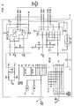
- the slave nodes such as the node 11 illustrated in Fig. 2, include a microcontroller 20, such as type 80C31 or 80C51.
- the serial communication ports SDBUS+ and SDBUS- of the slave node 11 are coupled to the serial terminals of the micro-controller via differential transceiver 21.
- a Core System Controller node
- various ports of the microcontroller of the slave node 11 are coupled to internal ROM 22 and RAM 23 as well as to port 24 for connection to the sub nodes.
- the RAM area (or registers) of the slave node that is commonly accessible by both the driver and an application program stored in ROM in the slave node consists of:
- a COM_STAT may area may additionally be provided in the master node.
- Initialization of the internal RAM in the slave node may be effected by the boot-exec program of the slave node.
- the master node and slave nodes communicate with one another only with messages of the following formats.:
- the 8031/8051 microcontroller is programmable to have a mode 2 operating mode for the UART function thereof, wherein the serial signals have 11 bits.
- the first bit is a start bit, and the next 8 bits are data bits.
- software allows a receive-interrupt only when the 9th bit is set. Whenever the 9th bit is set, the communication driver always restarts the receiving sequence.
- The ADD.CMD signal always originates in the master node, and is comprised of the following bits:
- the program of the master node includes polling sequences for polling the slave nodes and receiving messages therefrom, each polling sequence being followed by the transmission of a message from the master node, if the master node has a message to send.
- the slave nodes are all sequentially polled (at a rate of about 100 microseconds per node) or until a slave node sends a reply that it has a message to send, followed by the sending of the message.
- the master node waits 2 to 4 milliseconds to check if it has a message to send to the slave nodes. If no message is indicated to be present in its transmit buffer, it commences a new polling sequence. If the master node has a message to transmit, the message will be sent before a new polling sequence.
- a slave node transmits a message, that sequence will not be continued.
- the message is first transmitted to the master node.
- the next polling sequence will begin with the next slave node in the sequence, in order to equalize the opportunity for each slave node to transmit messages to the master node.
- the master node may have a poll table in order to keep track of the polling sequence, in order to assure such equal polling of all of the slave nodes.
- the time interval between the start of one byte transmission and the start of the next one, after the (REPLY) is exchanged, should not exceed 40us.
- the (ACK/NAK) should be received within 50 us after the last data CRCL is sent. Receiving is aborted if the receiving interval exceeds 200 us, i.e. the receiving of data from after the (REPLY) to the CRCL.
- a message exchange time for the longest one (35 bytes + 6 bytes overhead) should not exceed 1.5 ms.
- Idle polling time should be minimum 70 us (35*2) to maximum of 0.185 ms (0.35+0.15).
- the microcontroller is dedicated to communication, while transmitting or receiving, and all interrupts are disabled during this period.
- only a limited number of data bytes may be transmitted in each message, e.g. from 1 to 35.
- the programs of the master and slave nodes decompose large messages to small "packets" of data, up to 35 bytes, at the source nodes and reconstructs these packages at the destination nodes.
- the master and slave nodes do not know if a message being received is a large message, they only know that a message packet is being sent.
- the byte following the number of bytes field may be used by the system to enable the master system or slave system to reconstruct the message. This may be effected by the program of the master system, or by the slave sub nodes (if they are provided in the system).
- the application programs of the master and slave nodes should reserve appropriate amount of buffers in their RAM space. A byte count of zero is not allowed.
- the most significant bit (MSB) of the byte count is used for the transmitting sequence number. This MSB is transparent to an application program of the master and slave nodes.
- the systems externally of the interfaces masks out the MSB, use it, and pass out the value range 1 to 35 to an application program of the master system or sub nodes. It takes approximately 1.5 ms to transmit 35 data bytes and 6 bytes of the associated overhead, for a total of 41 bytes.
- the master node When the master node receives a message from its terminal, i.e. the master system, it must pass it on to the destination.
- the master node thus has a transmit buffer that must be empty before it can receive another message from its system. All messages from slave nodes to the master system must hence go first to the master node.
- a slave node If a slave node indicates to the master that it has a message to transmit, after the master node has received a slave node message but before the message is sent to the master system, the master node will first send the message from the slave node to the master system, and then it will send the master system message to the slave node.
- Message sequencing may be used to detect a duplicated message, i.e., an identical message is transmitted more than once due to the retransmission upon detecting an error condition.
- a duplication When a duplication is detected, the message is discarded.
- the master node transmits a message, and a slave node received it correctly, but suppose that (ACK) is not delivered from a slave to a master. Then, the master will re-transmit the same message, resulting in a duplicated message at the slave node.
- a transmission node sends a sequence number to a receiving node.
- After the transmitting node receives ACK or (ACK), it updates the transmit sequence number, finishing one cycle. At the end of each cycle, the transmit sequence number and the receive sequence number should be the same.
- a slave node maintains one pair of receive-transmit sequence numbers for the master node.
- the master node maintains one pair of receive-transmit sequence number for EACH slave node.
- Let variables MTxx, MRxx, STxx, and SRxx be for the master transmit sequence number for a slave node xx, the transmit sequence number for a slave node xx, the transmit sequence number in a slave node xx, and the receive sequence number in a slave node xx, respectively.
- the master is powered up, the sequence numbers (all one bit wide) are cleared by the set-up routine of the communication driver.
- sequence numbers are cleared (zeros).
- the master sends the command CMD-001 to a slave the above 4 variables (4 sequence numbers) are cleared.
- Communications between the master node and the master system, and between the slave node and slave sub nodes, may be effected by conventional means and protocols, with the flags of the nodes being set in conventional manner when the respective receive and transmit buffers are full.
Landscapes
- Engineering & Computer Science (AREA)
- Computer Networks & Wireless Communication (AREA)
- Signal Processing (AREA)
- Small-Scale Networks (AREA)
Applications Claiming Priority (2)
| Application Number | Priority Date | Filing Date | Title |
|---|---|---|---|
| US65778291A | 1991-02-19 | 1991-02-19 | |
| US657782 | 1991-02-19 |
Publications (2)
| Publication Number | Publication Date |
|---|---|
| EP0503323A2 true EP0503323A2 (fr) | 1992-09-16 |
| EP0503323A3 EP0503323A3 (en) | 1993-03-03 |
Family
ID=24638642
Family Applications (1)
| Application Number | Title | Priority Date | Filing Date |
|---|---|---|---|
| EP19920102777 Withdrawn EP0503323A3 (en) | 1991-02-19 | 1992-02-19 | Serial bus interface and method |
Country Status (2)
| Country | Link |
|---|---|
| EP (1) | EP0503323A3 (fr) |
| CA (1) | CA2061171A1 (fr) |
Cited By (4)
| Publication number | Priority date | Publication date | Assignee | Title |
|---|---|---|---|---|
| US5729701A (en) * | 1994-09-13 | 1998-03-17 | Telefonaktiebolaget Lm Ericsson | Method and arrangement to control a data network |
| US6907488B1 (en) * | 1999-09-14 | 2005-06-14 | Siemens Aktiengesellschaft | Serial data transmission via a bus system |
| CN112134771A (zh) * | 2019-06-25 | 2020-12-25 | 青岛海尔电冰箱有限公司 | 用于冰箱的半双工通信方法与冰箱 |
| CN120540178A (zh) * | 2025-07-16 | 2025-08-26 | 深圳市边界智控科技有限公司 | 基于rs485通信的电动垂直起降电传总线控制系统及方法 |
Family Cites Families (3)
| Publication number | Priority date | Publication date | Assignee | Title |
|---|---|---|---|---|
| US4839891A (en) * | 1987-07-24 | 1989-06-13 | Nec Corporation | Method for controlling data flow |
| DE3853118T2 (de) * | 1987-09-30 | 1995-06-14 | Hewlett Packard Co | Verfahren und Vorrichtung zur Datenübertragung. |
| US4926418A (en) * | 1989-04-11 | 1990-05-15 | International Business Machines Corporation | Fairness algorithm for full-duplex buffer insertion ring |
-
1992
- 1992-02-13 CA CA 2061171 patent/CA2061171A1/fr not_active Abandoned
- 1992-02-19 EP EP19920102777 patent/EP0503323A3/en not_active Withdrawn
Cited By (5)
| Publication number | Priority date | Publication date | Assignee | Title |
|---|---|---|---|---|
| US5729701A (en) * | 1994-09-13 | 1998-03-17 | Telefonaktiebolaget Lm Ericsson | Method and arrangement to control a data network |
| US6907488B1 (en) * | 1999-09-14 | 2005-06-14 | Siemens Aktiengesellschaft | Serial data transmission via a bus system |
| CN112134771A (zh) * | 2019-06-25 | 2020-12-25 | 青岛海尔电冰箱有限公司 | 用于冰箱的半双工通信方法与冰箱 |
| CN112134771B (zh) * | 2019-06-25 | 2022-03-29 | 青岛海尔电冰箱有限公司 | 用于冰箱的半双工通信方法与冰箱 |
| CN120540178A (zh) * | 2025-07-16 | 2025-08-26 | 深圳市边界智控科技有限公司 | 基于rs485通信的电动垂直起降电传总线控制系统及方法 |
Also Published As
| Publication number | Publication date |
|---|---|
| CA2061171A1 (fr) | 1992-08-20 |
| EP0503323A3 (en) | 1993-03-03 |
Similar Documents
| Publication | Publication Date | Title |
|---|---|---|
| US5446868A (en) | Network bridge method and apparatus | |
| EP0333715B1 (fr) | Reseau d'entree/sortie pour un systeme d'ordinateurs | |
| AU690297B2 (en) | Packet data protocol for wireless communication | |
| US4988990A (en) | Dual master implied token communication system | |
| US5122794A (en) | Dual master implied token communication system | |
| US5166678A (en) | Dual master implied token communication system | |
| EP0427502B1 (fr) | Automates programmables | |
| EP0156557A2 (fr) | Emetteur-récepteur pour réseau local à stations multiples | |
| US4773001A (en) | Method and apparatus for communicating with remote units of a distributive data processing system | |
| EP0076880A1 (fr) | Réseau local à contention pour système de communication de données | |
| AU655303B2 (en) | Method and apparatus for data collision detection in a multi-processor communication system | |
| GB2351884A (en) | Data transmission method | |
| US4675864A (en) | Serial bus system | |
| JPH0771125B2 (ja) | データ通信方法およびデータ通信システム | |
| US4638477A (en) | Packet exchange data transmission system | |
| EP0384078B1 (fr) | Réseau et protocole de commande en temps réel des opérations d'une machine | |
| EP0503323A2 (fr) | Interface pour bus série et le procédé | |
| EP0376513B1 (fr) | Réseau de communication et protocole pour la commande en temps réel des opérations d'une machine à traiter le courrier | |
| KR0165440B1 (ko) | 폴링통신방법 | |
| KR950001520B1 (ko) | 공통선 신호방식 메시지전달부의 신호단말 그룹버스 통신 프로토콜 | |
| US20020013805A1 (en) | LogNet: a low cost, high reliability network for embedded systems | |
| JPS6260050A (ja) | インタ−バス・システム | |
| JPS6236940A (ja) | 自動車内デ−タ通信装置 | |
| JPH0771089B2 (ja) | 通信システム | |
| JPS6121657A (ja) | 回線接続用アダプタ |
Legal Events
| Date | Code | Title | Description |
|---|---|---|---|
| PUAI | Public reference made under article 153(3) epc to a published international application that has entered the european phase |
Free format text: ORIGINAL CODE: 0009012 |
|
| AK | Designated contracting states |
Kind code of ref document: A2 Designated state(s): CH DE FR GB LI |
|
| PUAL | Search report despatched |
Free format text: ORIGINAL CODE: 0009013 |
|
| AK | Designated contracting states |
Kind code of ref document: A3 Designated state(s): CH DE FR GB LI |
|
| STAA | Information on the status of an ep patent application or granted ep patent |
Free format text: STATUS: THE APPLICATION HAS BEEN WITHDRAWN |
|
| 18W | Application withdrawn |
Withdrawal date: 19930407 |